EP1091065A2 - Elément de verrouillage pour une ferrure de verrouillage d'un vantail mobile d'une fenêtre ou d'une porte - Google Patents
Elément de verrouillage pour une ferrure de verrouillage d'un vantail mobile d'une fenêtre ou d'une porte Download PDFInfo
- Publication number
- EP1091065A2 EP1091065A2 EP00121749A EP00121749A EP1091065A2 EP 1091065 A2 EP1091065 A2 EP 1091065A2 EP 00121749 A EP00121749 A EP 00121749A EP 00121749 A EP00121749 A EP 00121749A EP 1091065 A2 EP1091065 A2 EP 1091065A2
- Authority
- EP
- European Patent Office
- Prior art keywords
- locking
- locking device
- guide plate
- slide
- groove
- Prior art date
- Legal status (The legal status is an assumption and is not a legal conclusion. Google has not performed a legal analysis and makes no representation as to the accuracy of the status listed.)
- Withdrawn
Links
Images


Classifications
-
- E—FIXED CONSTRUCTIONS
- E05—LOCKS; KEYS; WINDOW OR DOOR FITTINGS; SAFES
- E05C—BOLTS OR FASTENING DEVICES FOR WINGS, SPECIALLY FOR DOORS OR WINDOWS
- E05C9/00—Arrangements of simultaneously actuated bolts or other securing devices at well-separated positions on the same wing
- E05C9/18—Details of fastening means or of fixed retaining means for the ends of bars
- E05C9/1825—Fastening means
- E05C9/1833—Fastening means performing sliding movements
- E05C9/185—Fastening means performing sliding movements parallel with actuating bar
-
- E—FIXED CONSTRUCTIONS
- E05—LOCKS; KEYS; WINDOW OR DOOR FITTINGS; SAFES
- E05C—BOLTS OR FASTENING DEVICES FOR WINGS, SPECIALLY FOR DOORS OR WINDOWS
- E05C9/00—Arrangements of simultaneously actuated bolts or other securing devices at well-separated positions on the same wing
- E05C9/22—Guides for sliding bars, rods or cables
Definitions
- the invention relates to a locking device for a fitting - in particular one Locking bar fitting - for locking a movable frame part of a window or a door on a fixed frame part, the locking device in the movable frame part is arranged and has a locking pin which coupled with a locking or drive rod and with this on the movable frame part is slidably guided in a frame groove.
- a steel fitting and a plastic locking bar fitting are from the prior art of DE 35 45 861 known.
- the steel fitting has a faceplate that is screwed onto a frame profile groove is and under which a drive rod is arranged to be longitudinally movable.
- This Movable drive rod is guided under the faceplate and is among other things with Provide locking parts through elongated holes from the surface level of the faceplate protrude and to lock the casement in the frame or in corresponding frame components are used.
- the generic locking bar fitting of DE 35 45 861 lies in a form-fitting manner a specially designed frame profile groove of the movable frame part, with this locking bar the locking pins, similar to the drive rod of the steel fitting, are directly coupled to the locking bar in order to in turn move Lock wing on fixed wing.
- the invention sets in recognizing the problem, one separate from the locking bar To create a locking device which is designed such that the assembly of the fitting is simplified with increased functionality.
- the invention addresses this problem and solves it by the subject of Claim 1, according to which the locking device separately directly from the outside into the frame groove of the movable frame part or a single frame spar (if the Spars have not yet been assembled into the frame part) for the movable Frame part can be used.
- the inventive design of the locking device makes it possible to To anchor the locking device directly from the outside in the frame groove of the frame part, for example to screw.
- both fittings disadvantageous that due to a load on the locking pin the required large tolerance of the drive or locking bar in their guides can be easily rotated so that the locking pin engages behind do not absorb large forces with a corresponding locking piece of the frame can.
- the invention provides a locking device that - particularly advantageous vertically from above - can be inserted into the locking bar groove and thus for fully automatic assembly is suitable.
- the one that can be moved by the locking bar Locking device has a perfect guide, so that the locking device is exposed to only slight tolerances, causing undesirable tilting movements prevented and a lock ensures that even larger loads easily withstands.
- the locking device is preferably independent of the Latch or drive rod can be inserted into the frame groove (and preferably locked there) and / or with a bore for receiving the locking pin Provide locking device.
- the locking device particularly preferably comprises a in the frame groove of the frame part lockable guide element - preferably designed as a guide plate - And a sliding carriage guided on or in the guide element with the locking pin.
- a particular advantage of these can also be viewed independently Variant of the invention can be seen in the fact that the locking device or The locking unit can be positioned in the locking bar groove independently of the locking bar and can be locked.
- the locking bar serves only as a moving element. she does not have to absorb lateral forces transverse to the profile extension, which over the Locking device can be derived easily.
- the locking bars 4, 6, 8 have groove-shaped receptacles 20 for the edge strips 22 of a frame groove 24 on the groove-shaped receptacles 20 are bounded here by resilient webs (not visible here), which be elastically deformed when inserting the locking bars into the frame groove until Undercut surfaces (also not visible here) reach behind the edge strips 22. Since the locking bars 4, 6, 8 on the finished sash frame from the outside can be installed and also the other components of the locking bar fitting can be mounted on the sash frame from the outside, can be fully automatic of the components of the locking bar fitting. This is done preferably the coupling of the respective locking bar cut to its desired length 4, 6, 8 - which e.g.
- the locking bars can 4, 6, 8 can be fixed with clamping screws 26, for example lower ones Crosspieces (not visible here) on the groove-shaped receptacles 20 on the edge strips 22 press the frame groove 24 (also not shown here).
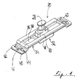
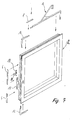
- the locking device 18 has a width that is not greater than the width of the opening of the locking bar groove 24, and - as indicated in FIG. 7 - can also from above "into the frame groove 24 and positioned and screwed independently of the locking bar 4, 6, 8 in the sash profile.
- the locking device 18 is therefore also suitable for fully automatic assembly.
- the locking device 18 has a locking pin 28 which is separated by a locking pin Bore 29 of the locking bar 4, 6, 8 is guided so that the locking pin 28 of the locking device 18 can be moved together with the locking bar 4, 6, 8.
- the locking device 18 shown in FIG. 1 essentially consists of three components: a relative to the bottom of the frame groove 24 upper guide plate 30, a in / "under” the guide plate slidably guided locking slide 32 and one advantageous (but purely optional) lower retaining tab 34.
- the closing device 18 can e.g. be designed as a zinc / die-cast version (especially the locking slide 32) and / or at least partially also consist of reinforced plastic.
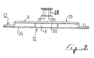
- the guide plate 30 essentially has a strip shape in a plan view and consists e.g. from a steel sheet, which in a hat rail-like in the side view Contour was formed (see also Fig. 2).
- a middle management section 36 with a central slot 38 is at its two opposite ends first bent vertically downwards and then again vertically outwards, so that the end portions of the guide portion are substantially stepped Connect mounting straps 40.
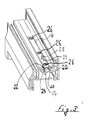
- the mounting tabs 40 are each with two outer recesses 44 for receiving locking cams 42 of the retaining tab 34 and bores 46 provided for receiving screws 47 (see Fig. 3) for screwing the locking device 18 in the groove base of the locking bar groove 24 serve.
- the slot 38 of the sturdy steel or aluminum sheet simple and straightforward producible guide plate 30 is used to guide the locking pin 28 of the closing slide 32. With this pairing, the tolerances can advantageously be narrow be interpreted.
- the locking slide 32 has a lower base area 48 which is larger Has width than the slot 38 and for guiding the locking slide 32 below the Guide plate 30 and for stable engagement behind the guide plate 30 is used.
- the base region 48 of the closing slide 32 is opened by the guide plate 30 the groove bottom of the frame groove 24 held.
- the tilting forces are derived by the guide plate 30 directly onto the frame profile 2. This ensures a very high level of stability and thus a high level of security against break-ins achieved with windows and doors, which with the invention Locking device are provided.
- a base area 50 is molded onto the base area 48 of the closing slide 32, which reaches through the elongated hole 38 of the guide plate 30 and from the locking bar 4, which generates the movement of the closing slide 32.
- the locking pin 28 is in turn molded / attached, the protrudes beyond the level of the locking bar 4 and from the level of the profile surface protrudes.
- the locking pin 28 is advantageous in the embodiment shown shaped as a so-called mushroom head; other variants are also conceivable, e.g. B. cylindrical Locking pin with and without rollers. The mushroom head can be used for this closing edges to increase the locking security of the construction to reach behind a security striker on the window frame (not shown here).
- the locking slide 32 is by the retaining tab 34 under the guide plate 32 held or secured.
- the function of the retaining tab 4 can also through other holding mechanisms - e.g. B. by undercuts on the locking slide - fulfilled become.
- the holding tab 34 is provided with locking cams 42 (or locking hooks) which in the Engage recesses 44 of the guide plate 30.
- the retaining tab 34 is preferred Made of a plastic, which also gives the sliding properties can be improved on the ground, especially if this construction is built into a metal profile.
- the locking bar lock with the clamping screws 26 is in the area of the screw connection performed with the screw 47 (see FIG. 3) for the guide plate 30, so that the guide plate 30 through the openings of the locking bar for the clamping screws 26 can be solved for disassembly, so that both the Locking device 18 and the locking bars in the groove direction from the locking bar / frame groove 24 can be pushed out.
- the locking device 18 and the locking bars 4, 6, 8 are from above inserted into the frame groove 24. Disassembly in this direction, however, is without destruction of the bolt undercuts is not possible.
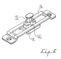
- FIG. 4 shows a variant of the locking device 18 without the optional lower retaining tab 34 shown.
- the closing slide 32 is in a simple manner at the top by cams 52, which each protrude laterally over the edge of the elongated hole 38, on the sides of the base area 50 and down through the base area 48 held on the guide plate 30.
- the locking slide is installed via the recesses 54 in the side areas at one end of the elongated hole 38, which are adapted to the geometry of the cams 52 so that it is possible to At this point, insert the slide carriage into the guide plate 30 from below and then screwed into the frame groove 24. As a result, the retaining tab 34 can be saved become.
- the retaining tab is saved in an even simpler way.
- the locking slide 32 is on the sides of the base area 50 provided smaller projections 56, which form a slight undercut.
- the locking slide 32 is in this variant of the invention when installed in the Guide plate 3 with so much pressure inserted into the slot 38 that the projections 56 snap onto the surface of the guide section 36. It is not because of this once again necessary, the recesses at the end of the elongated hole 38 in the manner of FIG. 4 to provide.
- Fig. 6 finally shows a variant of the invention, in which a locking of the Closing slide 32 by means of shear pins 58 formed / attached to the retaining tab 34 takes place, which in the assembly of the locking device 18 in corresponding bores / openings 60 engage in the bottom of the base area 48.
- the locking slide 32 is positioned in its assembly in the frame groove 24 so that the holes the locking bars 4, 6, 8 always with the locking pins during their subsequent assembly 28 are aligned without the locking slide 32 being carefully positioned first and / or would have to be locked.
- pins 58 are sheared off.
- the closing slide 32 can then move freely.
- the shear pins 56 can also be on the guide plate 34 for the closing slide 32 (not shown here). Is conceivable finally, positioning the shear pins 56 laterally to the locking slide 32 and shear off these side shear pins 56 upon the first actuation of the locking bar 2, 4, 6 with the locking slide 32 (also not shown here).
Landscapes
- Engineering & Computer Science (AREA)
- Mechanical Engineering (AREA)
- Wing Frames And Configurations (AREA)
- Lock And Its Accessories (AREA)
Applications Claiming Priority (2)
| Application Number | Priority Date | Filing Date | Title |
|---|---|---|---|
| DE1999148862 DE19948862A1 (de) | 1999-10-08 | 1999-10-08 | Schließeinrichtung für einen Beschlag zur Verriegelung eines beweglichen Rahmenteils eines Fensters oder einer Tür |
| DE19948862 | 1999-10-08 |
Publications (2)
| Publication Number | Publication Date |
|---|---|
| EP1091065A2 true EP1091065A2 (fr) | 2001-04-11 |
| EP1091065A3 EP1091065A3 (fr) | 2003-04-09 |
Family
ID=7925187
Family Applications (1)
| Application Number | Title | Priority Date | Filing Date |
|---|---|---|---|
| EP00121749A Withdrawn EP1091065A3 (fr) | 1999-10-08 | 2000-10-05 | Elément de verrouillage pour une ferrure de verrouillage d'un vantail mobile d'une fenêtre ou d'une porte |
Country Status (2)
| Country | Link |
|---|---|
| EP (1) | EP1091065A3 (fr) |
| DE (1) | DE19948862A1 (fr) |
Cited By (6)
| Publication number | Priority date | Publication date | Assignee | Title |
|---|---|---|---|---|
| DE10136316A1 (de) * | 2001-07-26 | 2003-02-13 | Winkhaus Fa August | Schließblech für einen Treibstangenbeschlag |
| RU2414577C1 (ru) * | 2007-01-24 | 2011-03-20 | Зигениа-Ауби Кг | Прибор (для створки или рамы) |
| EP2151537A3 (fr) * | 2008-08-07 | 2011-07-27 | Aug. Winkhaus GmbH & Co. KG | Partie de ferrure pour une ferrure de bielle |
| DE102013100308A1 (de) * | 2013-01-11 | 2014-07-17 | SCHÜCO International KG | Riegelstangenbeschlag für ein Fenster oder eine Tür |
| DE102023109404A1 (de) * | 2023-04-14 | 2024-10-17 | SCHÜCO International KG | Fenster mit einer Verriegelungseinrichtung zur Verriegelung eines Fensterflügels |
| EP4644647A1 (fr) * | 2024-04-30 | 2025-11-05 | AluK S.A. | Mécanisme de sélection et procédé de reconfiguration associé dans un kit d'actionnement pour une porte ou une fenêtre |
Families Citing this family (2)
| Publication number | Priority date | Publication date | Assignee | Title |
|---|---|---|---|---|
| ITBO20010080A1 (it) † | 2001-02-14 | 2002-08-14 | Gsg Int Spa | Metodo di realizzazione di elementi accessori per infissi ed apparecchiature attuante tale metodo |
| DE102016225133A1 (de) * | 2016-12-15 | 2018-06-21 | Roto Frank Ag | Beschlag mit einer eine Durchgangsöffnung aufweisenden Stulpschiene |
Citations (1)
| Publication number | Priority date | Publication date | Assignee | Title |
|---|---|---|---|---|
| DE3545861A1 (de) | 1985-12-23 | 1987-07-02 | Schuermann & Co Heinz | Fenster oder tuer mit einem durch einen handhebelgriff betaetigbaren riegelstangenbeschlag |
Family Cites Families (4)
| Publication number | Priority date | Publication date | Assignee | Title |
|---|---|---|---|---|
| DE7603368U1 (de) * | 1976-02-06 | 1976-06-03 | Wilh. Frank Gmbh, 7022 Leinfelden | Beschlagteil fuer ein fenster, eine tuer o.dgl. |
| DE3719011A1 (de) * | 1987-06-06 | 1988-12-22 | Bilstein August Gmbh Co Kg | Verriegelungsbeschlag fuer fenster, tueren od. dgl. |
| FR2722527B1 (fr) * | 1994-07-13 | 1996-12-27 | Alcan France Sa | Dispositif de verrouillage pour chassis a frappe |
| DE19909400A1 (de) * | 1999-03-04 | 2000-09-07 | Siegenia Frank Kg | Fenster oder Tür, Beschlag für ein Fenster oder eine Tür, sowie Verfahren zur Herstellung eines Fenster oder einer Tür |
-
1999
- 1999-10-08 DE DE1999148862 patent/DE19948862A1/de not_active Withdrawn
-
2000
- 2000-10-05 EP EP00121749A patent/EP1091065A3/fr not_active Withdrawn
Patent Citations (1)
| Publication number | Priority date | Publication date | Assignee | Title |
|---|---|---|---|---|
| DE3545861A1 (de) | 1985-12-23 | 1987-07-02 | Schuermann & Co Heinz | Fenster oder tuer mit einem durch einen handhebelgriff betaetigbaren riegelstangenbeschlag |
Cited By (6)
| Publication number | Priority date | Publication date | Assignee | Title |
|---|---|---|---|---|
| DE10136316A1 (de) * | 2001-07-26 | 2003-02-13 | Winkhaus Fa August | Schließblech für einen Treibstangenbeschlag |
| RU2414577C1 (ru) * | 2007-01-24 | 2011-03-20 | Зигениа-Ауби Кг | Прибор (для створки или рамы) |
| EP2151537A3 (fr) * | 2008-08-07 | 2011-07-27 | Aug. Winkhaus GmbH & Co. KG | Partie de ferrure pour une ferrure de bielle |
| DE102013100308A1 (de) * | 2013-01-11 | 2014-07-17 | SCHÜCO International KG | Riegelstangenbeschlag für ein Fenster oder eine Tür |
| DE102023109404A1 (de) * | 2023-04-14 | 2024-10-17 | SCHÜCO International KG | Fenster mit einer Verriegelungseinrichtung zur Verriegelung eines Fensterflügels |
| EP4644647A1 (fr) * | 2024-04-30 | 2025-11-05 | AluK S.A. | Mécanisme de sélection et procédé de reconfiguration associé dans un kit d'actionnement pour une porte ou une fenêtre |
Also Published As
| Publication number | Publication date |
|---|---|
| DE19948862A1 (de) | 2001-04-12 |
| EP1091065A3 (fr) | 2003-04-09 |
Similar Documents
| Publication | Publication Date | Title |
|---|---|---|
| EP1437471B1 (fr) | Ferrure pour une porte à soulèvement et coulissement ou une fenêtre à soulèvement | |
| CH624729A5 (fr) | ||
| EP4473182B1 (fr) | Agencement de profilé d'une fenêtre ou d'une porte ayant un profilé de châssis/battant, en particulier un profilé de châssis/battant coulissant | |
| EP3266969B1 (fr) | Renvoi d'angle d'une ferrure pour un battant de fenêtre ou de porte | |
| EP2252751B1 (fr) | Ferrure de tige d entraînement pour une fenêtre ou une porte | |
| EP1091065A2 (fr) | Elément de verrouillage pour une ferrure de verrouillage d'un vantail mobile d'une fenêtre ou d'une porte | |
| EP0844348B1 (fr) | Penture pour portes ou fenêtres | |
| DE102015206905A1 (de) | Getriebebeschlag sowie Fenster, Tür oder dergleichen mit einem Getriebebeschlag | |
| EP1264954B1 (fr) | Système de verouillage | |
| EP1681417A2 (fr) | Ferrure | |
| DE29601966U1 (de) | Zusatzschloß für Flügel von Türen, Fenstern o.dgl. | |
| EP0493689A1 (fr) | Tringlerie de commande pour fenêtres, portes ou similaires | |
| DE3334298C3 (de) | Verschluß für Fenster, Türen oder dergleichen | |
| DE19909400A1 (de) | Fenster oder Tür, Beschlag für ein Fenster oder eine Tür, sowie Verfahren zur Herstellung eines Fenster oder einer Tür | |
| EP3443185B1 (fr) | Ferrure de deux battants de fenêtres ou de portes, aptes au moins à être levés ou à coulisser | |
| EP4146888B1 (fr) | Ensemble charnière à actionnement commun | |
| EP1031692B1 (fr) | Couvercle pour fermetures dans fenêtres et/ou portes de bâtiments | |
| DE19734647B4 (de) | Beschlagteil an einem Flügel oder einem festen Rahmen eines Fensters, einer Tür od. dgl. | |
| EP2122092B1 (fr) | Ferrure | |
| EP3783176B1 (fr) | Ferrure de tige d'entraînement, fermeture de porte ou de fenêtre et agencement de porte ou de fenêtre | |
| DE102015206908A1 (de) | Fenster, Tür oder dergleichen mit einem Beschlag | |
| DE2805465A1 (de) | Beschlagsbaugruppe fuer fenster, tueren o.dgl. | |
| DE2411114C3 (de) | Beschlag für einen aus profilierten Rahmenteilen bestehenden Flügel von Fenstern, Türen od. dgl. | |
| EP3101207B1 (fr) | Dispositif de porte coulissante | |
| EP1270856B1 (fr) | Ferrure de verrouillage pour fenêtres ou portes |
Legal Events
| Date | Code | Title | Description |
|---|---|---|---|
| PUAI | Public reference made under article 153(3) epc to a published international application that has entered the european phase |
Free format text: ORIGINAL CODE: 0009012 |
|
| AK | Designated contracting states |
Kind code of ref document: A2 Designated state(s): AT BE CH CY DE DK ES FI FR GB GR IE IT LI LU MC NL PT SE |
|
| AX | Request for extension of the european patent |
Free format text: AL;LT PAYMENT 20001009;LV PAYMENT 20001009;MK;RO;SI |
|
| PUAL | Search report despatched |
Free format text: ORIGINAL CODE: 0009013 |
|
| AK | Designated contracting states |
Kind code of ref document: A3 Designated state(s): AT BE CH CY DE DK ES FI FR GB GR IE IT LI LU MC NL PT SE Designated state(s): AT BE CH CY DE DK ES FI FR GB GR IE IT LI LU MC NL PT SE |
|
| AX | Request for extension of the european patent |
Extension state: AL LT LV MK RO SI |
|
| RIC1 | Information provided on ipc code assigned before grant |
Ipc: 7E 05C 9/20 B Ipc: 7E 05C 9/22 B Ipc: 7E 05C 9/18 A |
|
| 17P | Request for examination filed |
Effective date: 20030925 |
|
| AKX | Designation fees paid |
Designated state(s): AT BE CH CY DE DK ES FI FR GB GR IE IT LI LU MC NL PT SE |
|
| AXX | Extension fees paid |
Extension state: LV Payment date: 20001009 Extension state: LT Payment date: 20001009 |
|
| 17Q | First examination report despatched |
Effective date: 20031219 |
|
| GRAP | Despatch of communication of intention to grant a patent |
Free format text: ORIGINAL CODE: EPIDOSNIGR1 |
|
| STAA | Information on the status of an ep patent application or granted ep patent |
Free format text: STATUS: THE APPLICATION IS DEEMED TO BE WITHDRAWN |
|
| 18D | Application deemed to be withdrawn |
Effective date: 20110503 |