EP1437471B1 - Ferrure pour une porte à soulèvement et coulissement ou une fenêtre à soulèvement - Google Patents
Ferrure pour une porte à soulèvement et coulissement ou une fenêtre à soulèvement Download PDFInfo
- Publication number
- EP1437471B1 EP1437471B1 EP04000038A EP04000038A EP1437471B1 EP 1437471 B1 EP1437471 B1 EP 1437471B1 EP 04000038 A EP04000038 A EP 04000038A EP 04000038 A EP04000038 A EP 04000038A EP 1437471 B1 EP1437471 B1 EP 1437471B1
- Authority
- EP
- European Patent Office
- Prior art keywords
- runner
- leaf
- sash
- groove
- casement
- Prior art date
- Legal status (The legal status is an assumption and is not a legal conclusion. Google has not performed a legal analysis and makes no representation as to the accuracy of the status listed.)
- Expired - Lifetime
Links
- 230000008878 coupling Effects 0.000 claims description 49
- 238000010168 coupling process Methods 0.000 claims description 49
- 238000005859 coupling reaction Methods 0.000 claims description 49
- 230000033001 locomotion Effects 0.000 claims description 11
- 239000002184 metal Substances 0.000 claims description 9
- 229910052751 metal Inorganic materials 0.000 claims description 9
- 239000004033 plastic Substances 0.000 claims description 7
- 229920003023 plastic Polymers 0.000 claims description 7
- 239000002023 wood Substances 0.000 claims description 5
- HCHKCACWOHOZIP-UHFFFAOYSA-N Zinc Chemical compound [Zn] HCHKCACWOHOZIP-UHFFFAOYSA-N 0.000 claims description 3
- 229910052725 zinc Inorganic materials 0.000 claims description 3
- 239000011701 zinc Substances 0.000 claims description 3
- 238000002347 injection Methods 0.000 claims description 2
- 239000007924 injection Substances 0.000 claims description 2
- 230000007704 transition Effects 0.000 claims description 2
- 230000002093 peripheral effect Effects 0.000 claims 1
- 230000005540 biological transmission Effects 0.000 description 11
- 238000004519 manufacturing process Methods 0.000 description 7
- 238000009434 installation Methods 0.000 description 5
- 239000000463 material Substances 0.000 description 4
- 230000008901 benefit Effects 0.000 description 3
- 230000009467 reduction Effects 0.000 description 3
- 238000007789 sealing Methods 0.000 description 3
- 235000003332 Ilex aquifolium Nutrition 0.000 description 2
- 241000209027 Ilex aquifolium Species 0.000 description 2
- 230000001154 acute effect Effects 0.000 description 2
- 230000015572 biosynthetic process Effects 0.000 description 2
- 230000008859 change Effects 0.000 description 2
- 238000006073 displacement reaction Methods 0.000 description 2
- 238000003801 milling Methods 0.000 description 2
- 238000012986 modification Methods 0.000 description 2
- 230000004048 modification Effects 0.000 description 2
- 229920000642 polymer Polymers 0.000 description 2
- 230000002787 reinforcement Effects 0.000 description 2
- QBWKPGNFQQJGFY-QLFBSQMISA-N 3-[(1r)-1-[(2r,6s)-2,6-dimethylmorpholin-4-yl]ethyl]-n-[6-methyl-3-(1h-pyrazol-4-yl)imidazo[1,2-a]pyrazin-8-yl]-1,2-thiazol-5-amine Chemical compound N1([C@H](C)C2=NSC(NC=3C4=NC=C(N4C=C(C)N=3)C3=CNN=C3)=C2)C[C@H](C)O[C@H](C)C1 QBWKPGNFQQJGFY-QLFBSQMISA-N 0.000 description 1
- 241001295925 Gegenes Species 0.000 description 1
- 241001236294 Hebe Species 0.000 description 1
- 240000006240 Linum usitatissimum Species 0.000 description 1
- 229910001229 Pot metal Inorganic materials 0.000 description 1
- 229910000639 Spring steel Inorganic materials 0.000 description 1
- 229910000831 Steel Inorganic materials 0.000 description 1
- 229940125846 compound 25 Drugs 0.000 description 1
- 238000010276 construction Methods 0.000 description 1
- 238000003745 diagnosis Methods 0.000 description 1
- 238000001125 extrusion Methods 0.000 description 1
- -1 for example Inorganic materials 0.000 description 1
- 238000001746 injection moulding Methods 0.000 description 1
- 230000002441 reversible effect Effects 0.000 description 1
- 239000010959 steel Substances 0.000 description 1
- 230000003313 weakening effect Effects 0.000 description 1
Images


Classifications
-
- E—FIXED CONSTRUCTIONS
- E05—LOCKS; KEYS; WINDOW OR DOOR FITTINGS; SAFES
- E05D—HINGES OR SUSPENSION DEVICES FOR DOORS, WINDOWS OR WINGS
- E05D15/00—Suspension arrangements for wings
- E05D15/56—Suspension arrangements for wings with successive different movements
- E05D15/565—Suspension arrangements for wings with successive different movements for raising wings before sliding
-
- E—FIXED CONSTRUCTIONS
- E05—LOCKS; KEYS; WINDOW OR DOOR FITTINGS; SAFES
- E05Y—INDEXING SCHEME ASSOCIATED WITH SUBCLASSES E05D AND E05F, RELATING TO CONSTRUCTION ELEMENTS, ELECTRIC CONTROL, POWER SUPPLY, POWER SIGNAL OR TRANSMISSION, USER INTERFACES, MOUNTING OR COUPLING, DETAILS, ACCESSORIES, AUXILIARY OPERATIONS NOT OTHERWISE PROVIDED FOR, APPLICATION THEREOF
- E05Y2800/00—Details, accessories and auxiliary operations not otherwise provided for
-
- E—FIXED CONSTRUCTIONS
- E05—LOCKS; KEYS; WINDOW OR DOOR FITTINGS; SAFES
- E05Y—INDEXING SCHEME ASSOCIATED WITH SUBCLASSES E05D AND E05F, RELATING TO CONSTRUCTION ELEMENTS, ELECTRIC CONTROL, POWER SUPPLY, POWER SIGNAL OR TRANSMISSION, USER INTERFACES, MOUNTING OR COUPLING, DETAILS, ACCESSORIES, AUXILIARY OPERATIONS NOT OTHERWISE PROVIDED FOR, APPLICATION THEREOF
- E05Y2900/00—Application of doors, windows, wings or fittings thereof
- E05Y2900/10—Application of doors, windows, wings or fittings thereof for buildings or parts thereof
- E05Y2900/13—Type of wing
- E05Y2900/132—Doors
-
- E—FIXED CONSTRUCTIONS
- E05—LOCKS; KEYS; WINDOW OR DOOR FITTINGS; SAFES
- E05Y—INDEXING SCHEME ASSOCIATED WITH SUBCLASSES E05D AND E05F, RELATING TO CONSTRUCTION ELEMENTS, ELECTRIC CONTROL, POWER SUPPLY, POWER SIGNAL OR TRANSMISSION, USER INTERFACES, MOUNTING OR COUPLING, DETAILS, ACCESSORIES, AUXILIARY OPERATIONS NOT OTHERWISE PROVIDED FOR, APPLICATION THEREOF
- E05Y2900/00—Application of doors, windows, wings or fittings thereof
- E05Y2900/10—Application of doors, windows, wings or fittings thereof for buildings or parts thereof
- E05Y2900/13—Type of wing
- E05Y2900/148—Windows
Definitions
- the invention relates to a fitting for lift-slide doors or windows according to the preamble of claim 1 and to a lift-slide door or a lift-slide window according to the preamble of claim 15.
- Lifting and sliding doors or lifting and sliding windows as well as suitable fittings for these doors are known.
- the basic function of such doors or windows is that the respective door or window sash is raised and lowered relative to an outer floor frame and at the same time is displaceable in the wing plane, so that, for example, to open the closed wing this first raised in the vertical direction and then is shifted in the horizontal direction. In the reverse manner, the closing of the wing.
- lifting and sliding doors can also have a tilt function.
- U-shaped cuff rails are generally used in lifting-sliding doors or windows so far, which lead the respective drive rod slidably between their legs and are supported by the free edges of their legs at the bottom of the groove.
- the disadvantage here is that such U-shaped cuff rails are bulky, heavy and expensive and also require in the rebate a groove (Einbaunut) with a relatively large width, and that conditionally on the one hand by the additional material thickness of the legs and in particular also due to the fact that when using the manually operable transmission, the U-shaped face-plate has to overlap the housing of this transmission.
- Fittings are also known in which the corner drive consists of several lamellar spring steel strips arranged one above the other ( DE 34 40 505 ) or is formed by a chain ( DE 72 44 800 ).
- These embodiments have the disadvantage that the transmission of shear or compressive forces is insufficient and therefore the lowering of the door leaf must be supported by the weight of this wing at least for this reason. The latter affects, inter alia, the free design possibility of acting between the running shoe and the associated bearing element lifting curve.
- the object of the invention is to show a fitting (espagnolette fitting), which can be made particularly inexpensive in a reliable operation and also allows a reduction in the width and / or depth of the installation groove.
- a lift-slide door or a lift-and-slide window is designed according to claim 15.
- the faceplate of a fitting for lifting-sliding doors or windows is flat or flat-band-like design.
- the Eckumlenkung is formed by a rigid, rod-like or pressure and Switzerland Swissianon coupling piece, which is guided displaceably in the bearing element.
- a bell-like, two-armed lever and the associated disadvantages, in particular an additional manufacturing effort and a relatively large space requirement during installation, are thus avoided.
- rod-like or pressure and Switzerland Glanite training of the clutch gap this is able to transmit both tensile forces and compressive forces reliably on the running shoe.
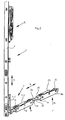
- FIG. 1 shows a building door, which consists in a conventional manner from the floor or window frame 1 and from the door provided in this frame 2, which formed as a lift-slide-wings, for example, with additional tilting function is, that can be raised or lowered for opening and closing in the vertical direction and is displaceable and tiltable.
- wing 2 or on the sash of the lifting and sliding fitting is provided in a known manner, which is generally denoted by 3 in the figures and, inter alia, attached to a vertical fold of the sash 2.1 faceplate 4, which there with a not shown Handle operable lifting gear 5 and on the face plate 4 axially displaceable (double arrow V) and driven by the transmission 5 drive rod 6 has. That in the Figures 2 . 3 and 4 lower end of the faceplate 4 is connected to a leg 7.1 of an angular bearing element 7, which is made of a suitable material, for example of plastic or metal.
- the bearing element 7 is connected to the leg 7.1, which is oriented in the mounted state of the fitting 3 in the vertical direction, with the face plate 4, for example by screws or rivets.
- the housing 8 is in the illustrated embodiment in one piece of a suitable material, for example of metal, e.g. manufactured as a metal injection molding (zinc injection molded part), with two extending in the longitudinal direction of the running shoe 2 parallel housing walls 10, which are connected to each other at the two ends of the housing by corresponding walls 11. Between the two ends, the walls 10 are still connected by additional stiffening walls 11.1.
- a suitable material for example of metal, e.g. manufactured as a metal injection molding (zinc injection molded part)
- rollers 12 are freely rotatably supported in the darg Congressen embodiment, namely about axes perpendicular to the plane of the door leaf 2.
- the rollers 12 are in a known manner with a at the bottom of the element Stock frame 1 provided rail 13 in engagement, which is also made of metal, for example.
- an oblique lifting cam is provided on the leg 7.2, in the form of an oblique, slot-like opening 14, which encloses an acute angle with the longitudinal extent of the leg 7.2.
- the opening 14 is provided on a projection 15 which is received between the walls 10, projects from the Matfl ügel adjacent side of the leg 7.2 in the housing 8 of the running shoe and lateral guide surfaces for the inner surfaces of the longitudinal walls 10 forms.
- a coupling piece 17 is provided which is rigidly designed as a pressure and Switzerland and formed in the illustrated embodiment as part of a ring.
- a circular arc-shaped guide is formed in the bearing element 7 in the region of the corner between the legs 7.1 and 7.2 of wall sections 18 and 19, a circular arc-shaped guide, in such a way that the coupling piece 17 in this guide on a circular arc about an axis perpendicular to the plane of the door leaf is movable (double arrow K).
- the coupling piece 17 is provided on its outer, ie convexly curved side with a plurality of teeth 20 forming a toothing.
- This gearing engages in openings 6.1 at the lower end of the drive rod 6, so that the axial movement of the drive rod 6 (double arrow V) the coupling piece 17th corresponding to the double arrow K performs a longitudinal movement in the form of a circular motion.
- the teeth 20 remote from the end of the coupling piece 17 is pivotally connected to the coupling piece adjacent this end of the running shoe 6, and in fact that the relevant end engages with a hook-like portion 21 in an opening 22.1 provided on the end wall 11 ⁇ senabitess 22.
- the coupling piece 17 engages with its portion 21 from above into the recess 22.1 of the eyelet portion 22 and engages behind an edge of the eyelet portion 22 with a rounded surface 21.1 formed on the portion 21.
- the training is further made such that the section 21 is guided at two in an axial direction perpendicular to the wing plane or parallel to the axis of rotation of the rollers 12 staggered side surfaces of surfaces within the recess 22.1, whereby the movements of the coupling piece 17 and the running shoe. 9 are stabilized when raising and lowering the door leaf 2.
- FIG. 4 shows the axis of the circular arc movement of the coupling piece 17 is within the angular space formed by the legs 7.1 and 7.2, and perpendicular to a plane which is defined by the longitudinal axes of these legs.
- the coupling piece 17 of the illustrated fitting 3 avoids the usual in lifting and sliding fittings pivotable deflection bell. This results in a very simple and reliable construction. Due to the formation of the coupling piece 17 at the one end as a circular arc-shaped toothed rack reliable drive connection between the drive rod 6 and the coupling piece 17 and the running shoe 9 is ensured, namely a driving connection through which both tensile forces for lifting the door, as Also shear forces for lowering the door leaf 2 can be effectively transferred. Another advantage of the deflection using the coupling piece 17 is that the bearing element 7 can be formed very small volume in the region of this deflection, which is therefore kept small for the installation in the door 2 required space.
- a further running shoe 24 is provided, in the region of the bearing element 7 remote second lower corner of the sash 2.1.
- the bearing element 23 is similar to the leg 7.2 of the bearing element 7 is formed.
- the running shoe 24 corresponds to the running shoe 9. Both running shoe 9 and 24 are connected in a known manner via a connecting member 25 with each other, which is suitable for the transmission of compressive and tensile forces.
- This connecting member 25 is, for example, a connecting rod, which is fastened at its ends to the running shoes 9 and 24, by engaging in sleeve-like coupling or connecting portions 26, the front of the respective shoe housing 8 and 8a, ie in the region of the end wall 11th are formed.
- the running shoe housing 8a of the running shoe 24 differs from the running shoe housing 8 only in that a coupling section 26 is located on both end walls 11 of the running shoe housing 8a.
- FIG. 7 shows the installation state of the bearing element 7 and the leg 7.2. This is taken up together with the running shoe 9 in a groove 27 provided on the underside of the door leaf. On both sides of the groove two extending over the entire width of this door leaf seals 28 are provided on the underside of the door, which bear against a sealing surface 13.1 of the track rail 13 when lowered, ie closed door 2.
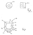
- FIG. 8 shows in cross-section a connection 25 or connecting rod 25.1 with a circular cross-section and a connecting rod 25.2 with a square cross section, which can be used optionally as a compound 25.
- the cross sections of the two connecting rods are coordinated so that the diagnosis of the cross section of the square connecting rod 25.2 is slightly larger than the Druchmesser or twice the radius of the cross section of the connecting rod 25.1.
- the coupling section 26 integrally formed on the respective end of the running shoe housing 8 or 8a has an opening 29 whose cross-sectional shape initially corresponds to a square cross section, combined with a circular cross section in such a way that in that each of the four sides of the cross section has a circular cylindrical curved portion 30 corresponding to the circular cross section, and those portions 30 curved about the common center axis of the sleeve opening 29 are formed so as to obtain the corner portions 31 of the square cross section, ie there are perpendicular to adjacent surfaces.
- This means that the radius of curvature of the curved regions 30 is again smaller than half the distance between two diagonally opposite corner regions 31.
- the respective connecting rod 25.1 or 25.2 is inserted with one end into the opening 29 of a sleeve-like coupling portion 26 on the running shoe housing 8 and 8a and then provided with this coupling portion 26 locking means, for example Clamping screws 32 clamped.
- connecting rods 25.1 and 25.2 can be used on the market inexpensively available rod profiles made of metal, for example steel.
- the total cross section of these connecting rods can be kept relatively small, since in the case of use, the respective connection 25 or connecting rod 25.1 or 25.2 is essentially claimed only to train.
- the longitudinal extent of the respective lifting curve closes with the horizontal (axial direction of the double arrow H). an acute angle ⁇ , ie an angle ⁇ less than 90 ° ( Fig. 4 ), which opens in the running shoe 9 to the corner 7 and in the running shoe 24 from the running shoe 9 out.
- This course of the lift curve results in the tensile load in the connection 25 due to the weight of the door leaf 3. Compressive forces do not occur in this connection.
- FIG. 10-16 is designated 101 building door, which in turn has an outer floor or frame 102, provided in this frame fixed space 103 with the associated frame 104 and the associated glazing 105 and a wing 106 which is formed as a lifting and sliding wings.
- the wing 106 in turn, consists of the wing frame 107, which has the glazing 108 and is composed of four wing frame elements, which adjoin one another at right angles, from a sash profile, e.g. is made of wood, namely from the lower horizontal sash member 107.1, the opening or transmission side of the wing 106 forming vertical sash member 107.2, the upper horizontal sash member 107.3 and the other vertical sash member 107.4.
- a sash profile e.g. is made of wood
- the hand lever 109 having a gear 110 is provided, with which a provided in the fold of the sash frame 107 espagnolette u.a. a locking or unlocking of the wing 106 moved to the closed position is also possible on the frame 102 as well as the raising and lowering of the wing 106 for opening or closing.
- the wing 106 can be moved in the raised state parallel to its wing plane or parallel to the plane of the fixed field 103 in the horizontal direction.
- two running shoes or carriages 111 are provided in the illustrated embodiment at the lower horizontal sash member 107.1, which in the FIG. 10 only with their carriage rollers 112 schematically are indicated and which are guided with these rollers 112 in a horizontal guide rail.
- the two carriages 111 are formed with corresponding actuatable via the espagnolette lifting means.
- FIG. 11 shows a simplified representation of the lower, horizontal sash element 107.1 in a sash frame 107 made of wood.
- a groove 113 is introduced, which is open to the bottom of the sash member 107.1 out and lies in the illustrated embodiment with its center plane in the vertical center plane of the sash member 107.1.
- the groove 113 serves to receive the carriages 111, which are provided offset in this groove in the longitudinal direction of the sash member 107.1 against each other, but for the raising and lowering of the wing 106 are drivingly connected to each other.
- Each carriage 111 is attached to a carriage carrier 114 at the bottom 113.1 of the groove 113 in a suitable manner, for example by screwing.
- the carriage rollers 112 are freely rotatably mounted on a carriage or running shoe housing 115.
- the carriage housing 115 is connected for lifting and lowering of the wing 106 with the carriage carrier on the lifting means, which are formed in the simplest case of a lifting cam on the carriage carrier 114 and a cooperating with this lifting cam guide or sliding pin on the carriage housing 115.
- the depth of the groove 113 is selected so that, at least when the wing 106 is lowered, the carriages 111 with all their elements, including their carriage rollers 112, are almost completely received in the groove 113.
- the groove 113 is slightly widened, ie provided on both sides with a recess 116 so that each side surface 113.2 of the groove in the region of these recesses each forms a step with a surface 113.3, which lies in a plane perpendicular to the median plane of the groove 113 ,
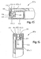
- FIG. 12 shows a section through the vertical sash frame element 107.2 of the sash made of wood frame 107. Also in the sash member 107.2 is at the fold or at the closed wing 106 of the frame 102 adjacent outer side of the sash 107 again the groove 113 with the two recesses 116th and introduced with the additional grooves 117 for the seals.
- the groove 113 serves to attach the faceplate 118 of the aforementioned espagnolette fitting.
- the faceplate 118 is formed as a flat, band or strip-like (flat-band-like) rail and anchored via suitable fasteners 119 in the groove 113, in such a way that the faceplate 118 on its groove 113 facing side in an edge region of its longitudinal sides against the The recesses 116 formed surfaces 113.3 rests and covers the groove 113 to the outside.
- a likewise flat band-like drive rod 120 is slidably guided on the face plate 118 in the longitudinal direction.
- the drive rod 120 is drivingly connected to the gear 110 and controls, inter alia, via a not shown Eckumlenkung, as for example, those skilled in the DE 203 04 001 U is known, the carriage 111 for raising and lowering the wing 106th
- the flat band-like design of the faceplate 118 has, in addition to, in particular, a material and cost saving in particular also the advantage that the groove 113 at least outside of the recesses 116, ie over the greater part of their depth can be made relatively narrow, ie the groove width can be reduced from the current standard width of about 22 mm to about 16 mm, which at the same outer dimensions of the wood frame used for the sash 107 to a substantial increase in the strength of the sash 107 and thus u , a leads to an increase in burglar resistance, or allows a more compact design, in particular by reducing the dimensions of the profile used for the casement 107.
- FIG. 13 shows a section through the upper horizontal sash element.
- the groove 113 is provided with the two recesses 116, together with the provided on both sides of the groove 113 grooves 117 for the seal.
- an H-shaped profile 121 is inserted on the casement element 107.3 and secured in a suitable manner.
- a guide piece 122 is resiliently mounted in one piece, with which the wing 106 is guided on its upper side, ie with its sash element 107.3 on the frame 102 for raising and lowering and for moving.
- FIGS. 11-13 show is in all sash elements 107.1, 107.2 and 107.3 the local, necessary to accommodate the functional elements groove 113 formed identically, which also means a significant simplification and cost savings in manufacturing, since each same tools for the grooves 113 on all sash elements 107.1, 107.2 and 107.3 can be used.
- each groove 117 is located on a sash element 107.1 - 107.3 in a common plane with the corresponding groove on the other sash elements, so that the recorded in the grooves 117 of the sash elements 107.1 - 107.2 seals performed as a continuous seals can be and thus optimal sealing is achieved with the wing closed 106.
- FIGS. 14-16 show cuts similar to the FIGS. 12-13
- the sash elements 107a.1, 107a.2 and 107a.3 are each formed by a multi-chamber plastic profile with an internal metal reinforcement 123.
- the groove 113 with the two recesses 116 and with the contact surfaces 113.3 formed by these recesses and with the additional grooves 117 is again provided in all casement elements 107a.1, 107a.2 and 107a.3.
- the groove 113 again essentially serves to receive the two carriages 111, the casement element 107a.2 for receiving and fastening the flat-band-shaped cuff rail 118 with the drive rod 118 and the casement element 107a.3 for receiving the H profile 121 the guide piece 122.
Landscapes
- Engineering & Computer Science (AREA)
- Mechanical Engineering (AREA)
- Power-Operated Mechanisms For Wings (AREA)
- Wing Frames And Configurations (AREA)
Claims (20)
- Ferrure pour portes ou fenêtres à soulèvement et coulissement comportant au moins un rail de têtière (4, 118) pouvant être fixé dans une rainure du côté du battant d'un battant de porte ou de fenêtre (2) et une tige de commande pouvant coulisser axialement sur le rail de têtière, avec au moins un sabot de déplacement (9, 24, 111) prévu sur un élément porteur (7, 114) pouvant être monté dans la rainure (113) du côté du battant et qui, pour le soulèvement et l'abaissement du battant de porte ou de fenêtre (2), peut se déplacer dans un axe longitudinal du sabot de déplacement par rapport à l'élément porteur (7, 114), ainsi qu'un élément d'accouplement (17) qui, pour ce mouvement, relie au moins un sabot de déplacement (9, 24, 111) avec une tige de commande à prévoir à une section verticale d'un cadre de battant (2.1), caractérisé en ce que le rail de têtière (4, 118) est configuré en bande plate, que la largeur du rail de têtière est supérieure à la largeur de la tige de commande, et que le rail de têtière (4, 118) forme avec des zones périphériques des surfaces de contact à mettre en contact des deux côtés avec des surfaces d'appui du côté du battant, lesquelles sont formées par des évidements (116) sur le bord d'ouverture de la rainure (113), la rainure (113) présentant la même largeur tout au long.
- Ferrure suivant la revendication 1, caractérisée en ce que l'élément de couplage (17) est une pièce d'accouplement (17) rigide, de type tige et / ou à pression et traction, qui est guidée de manière à pouvoir coulisser dans l'élément de support (7) et est reliée par une première extrémité avec la tige de commande (6) et avec une deuxième extrémité est reliée de manière articulée avec le sabot de déplacement (9).
- Ferrure suivant la revendication 1 ou 2, caractérisée en ce que la pièce d'accouplement (17) présente la forme d'un anneau partiel et est placée dans l'élément de support (7) de manière que l'axe de l'anneau se trouve dans un plan perpendiculaire à l'axe du battant de la porte.
- Ferrure suivant l'une quelconque des revendications qui précèdent, caractérisée en ce que la pièce d'accouplement (17) est configurée à sa première extrémité en forme de crémaillère à plusieurs dents (20) et coopère par cette extrémité avec une section dentée ou perforée (6.1) de l'élément d'entraînement (6).
- Ferrure suivant l'une quelconque des revendications qui précèdent, caractérisée en ce que la pièce d'accouplement (17) s'engage par son autre extrémité dans une ouverture d'accouplement (22.1) du sabot de déplacement (9) ou du logement (8) du sabot d'accouplement.
- Ferrure suivant l'une quelconque des revendications qui précèdent, caractérisée en ce que la pièce d'accouplement (17) présente, au moins entre ses deux extrémités, une section transversale s'écartant de la forme circulaire, en particulier une section transversale rectangulaire ou carrée.
- Ferrure suivant l'une quelconque des revendications qui précèdent, caractérisée par un guidage en arc de cercle (18, 19) dans l'élément de support (7) pour la pièce d'accouplement (17).
- Ferrure suivant l'une quelconque des revendications qui précèdent, caractérisée en ce que l'élément de support (7) est configuré en une pièce coudée à deux branches (7.1, 7.2), et en ce que la pièce d'accouplement (17) est prévue dans la zone de transition entre les deux branches (7.1, 7.2) dans l'élément de support (7).
- Ferrure suivant la revendication 8, caractérisée en ce qu'à l'une des branches est amenée la tige de commande (6, 120) et qu'à l'autre extrémité est placé le sabot de déplacement (9).
- Ferrure suivant l'une quelconque des revendications qui précèdent, caractérisée en ce que le logement (8) du sabot de déplacement présente deux parois longitudinales s'étendant dans la direction longitudinale du sabot de déplacement et distantes l'une de l'autre, et qu'entre les parois (10) se trouvent au moins deux galets (12) de roulement, et que les parois longitudinales (10) du logement (8) du sabot de déplacement sont reliées, au moins aux extrémités du sabot de déplacement, par des parois frontales (11).
- Ferrure suivant l'une quelconque des revendications qui précèdent, caractérisée en ce que, sur l'élément de support (7), il est prévu au moins une protubérance (15) formant un guidage pour le sabot de déplacement (9), et qu'à la protubérance (15) est formée une courbe de levage (14), avec laquelle coopère un élément de guidage ou de glissement du sabot de déplacement (9) pour le levage et l'abaissement.
- Ferrure suivant la revendication 11, caractérisée en ce qu'au moins une protubérance (15) aboutit dans le logement (8) du sabot de déplacement et forme des surfaces de guidage latérales pour les surfaces intérieures du logement (8) du sabot de déplacement.
- Ferrure suivant l'une quelconque des revendications qui précèdent, caractérisée en ce que le logement (8) du sabot de déplacement (9, 24, 111) est fabriqué d'un seul tenant avec au moins une section d'accouplement (26) de type manchon prévue à une extrémité du sabot de déplacement, et de fait par exemple en métal, de préférence en zinc moulé par injection.
- Ferrure suivant la revendication 13, caractérisée en ce que la section d'accouplement (26) de type manchon présente une ouverture en manchon (29) ayant une section transversale composée d'une forme de section transversale carrée et d'une forme de section transversale circulaire, de manière à former quatre côtés avec à chaque fois une section (30) de forme cylindrique circulaire et quatre zones de coin avec des surfaces (31) se rejoignant à angle droit, que les sections (30) se trouvent sur une surface cylindrique circulaire imaginaire commune autour de l'axe central de l'ouverture en manchon (29) et que le rayon des sections (30) de forme cylindrique circulaire est légèrement inférieur à la moitié de la distance entre deux zones de coin (31) diagonalement opposées, de manière que la section d'accouplement en manchon respective (26) puisse, au choix, être utilisée pour une tige de liaison (25,1, 25,2) ayant une section transversale circulaire ou carrée, et que les moyens de fixation (32) pour la fixation des tiges de liaison respectives (5.1, 25.2) soient prévus dans l'ouverture en manchon (29).
- Porte ou fenêtre à soulèvement - coulissement comportant au moins un battant de porte ou de fenêtre (2, 106) agencé dans un cadre dormant de porte ou de fenêtre (1, 102) avec des patins de déplacement (9, 24, 111) prévus dans une rainure (113) du côté battant sur un élément de cadre de battant inférieur horizontal (107.1, 104a.1) pour le soulèvement et l'abaissement ainsi que pour le coulissement du battant (2, 106), avec un mécanisme de commande (5, 110) prévu à un élément de cadre de battant vertical (107.2, 107a.2), qui est relié, pour le soulèvement et l'abaissement du battant (2, 106), et via une tige de commande (6, 120) logée dans un rail de têtière (4, 118), couplé en entraînement avec les sabots de déplacement (9, 24, 111), le rail de têtière (4, 118) étant fixé à la tige de commande (6, 120) dans la zone de la rainure (113) côté battant de l'élément de cadre de battant de porte vertical (107.2, 107a.2)" et le rail de têtière (4, 118), la tige de commande (120) ainsi que les sabots de déplacement (9, 24, 111) faisant partie d'une ferrure, caractérisée en ce que la rainure (113) côté battant est à chaque fois munie d'un évidement (116), des deux côtés de son bord d'ouverture, d'un évidement (116), lesquels forment les surfaces d'appui (113.3) côté battant, et que la ferrure est en conséquence configurée suivant l'une quelconque des revendications qui précèdent, la rainure (M3) présentant la même largeur tout du long.
- Porte ou fenêtre à soulèvement - coulissement suivant l'une quelconque des revendications qui précèdent, caractérisée en ce que la rainure (113) présente une largeur égale ou pratiquement égale à la largeur de la tige de commande (120).
- Porte ou fenêtre à soulèvement - coulissement suivant l'une quelconque des revendications qui précèdent, caractérisée en ce qu'au moins un autre élément de cadre de battant formant le cadre de battant (107, 107a), de préférence un élément de cadre de battant (107.3, 107a.3) formant le côté supérieur du battant (106) présente aussi la rainure (113) côté battant, laquelle est configurée de manière identique dans touts les zones.
- Porte ou fenêtre à soulèvement - coulissement suivant l'une quelconque des revendications qui précèdent, caractérisée en ce qu'il est prévu, dans la rainure (113) du côté battant de l'élément de cadre de battant (107.3, 107a.3) formant le côté supérieur du cadre de battant (107, 107a), un profil (121) avec un élément de guidage ou une pièce de guidage (122).
- Porte ou fenêtre à soulèvement - coulissement suivant l'une quelconque des revendications qui précèdent, caractérisée en ce que en ce que les éléments de cadre de battant (107.1, 107.2, 107.3, 107.4, 107a.1, 107a.2, 107a.3, 107a.4) formant le cadre de battant (2.1, 107, 107a), sont des profils en bois et / ou de matière synthétique.
- Porte ou fenêtre à soulèvement - coulissement suivant l'une quelconque des revendications qui précèdent,, caractérisée en ce que la largeur du rail de têtière (4, 118) est supérieure à la largeur de la tige de commande (6, 120), et supérieure à la largeur de la rainure côté battant (113) dans la zone du au moins un sabot de déplacement (9, 24, 111) et dès lors aussi supérieure à la largeur du sabot de déplacement (9, 24, 111).
Applications Claiming Priority (6)
| Application Number | Priority Date | Filing Date | Title |
|---|---|---|---|
| DE20300403 | 2003-01-10 | ||
| DE20300403U | 2003-01-10 | ||
| DE20304001U DE20304001U1 (de) | 2003-01-10 | 2003-03-13 | Beschlag für Hebe-Schiebe-Türen oder -Fenster sowie Laufschuh für einen solchen Beschlag |
| DE20304001U | 2003-03-13 | ||
| DE20313145U DE20313145U1 (de) | 2003-08-22 | 2003-08-22 | Hebe-Schiebe-Tür oder -Fenster sowie Treibstangenbeschlag für Hebe-Schiebe-Türen oder -Fenster |
| DE20313145U | 2003-08-22 |
Publications (3)
| Publication Number | Publication Date |
|---|---|
| EP1437471A2 EP1437471A2 (fr) | 2004-07-14 |
| EP1437471A3 EP1437471A3 (fr) | 2005-01-12 |
| EP1437471B1 true EP1437471B1 (fr) | 2008-12-24 |
Family
ID=32511974
Family Applications (1)
| Application Number | Title | Priority Date | Filing Date |
|---|---|---|---|
| EP04000038A Expired - Lifetime EP1437471B1 (fr) | 2003-01-10 | 2004-01-03 | Ferrure pour une porte à soulèvement et coulissement ou une fenêtre à soulèvement |
Country Status (2)
| Country | Link |
|---|---|
| US (1) | US20040163317A1 (fr) |
| EP (1) | EP1437471B1 (fr) |
Cited By (1)
| Publication number | Priority date | Publication date | Assignee | Title |
|---|---|---|---|---|
| DE102015011292A1 (de) | 2015-09-01 | 2017-03-02 | Siegenia-Aubi Kg | Kupplungsvorrichtung für Hebe-Schiebe-Türen oder -Fenster und Verfahren |
Families Citing this family (29)
| Publication number | Priority date | Publication date | Assignee | Title |
|---|---|---|---|---|
| KR100721455B1 (ko) * | 2005-12-21 | 2007-05-23 | 주식회사 엘지화학 | 시스템창호 개폐장치 |
| EP1891292B1 (fr) * | 2005-12-21 | 2014-07-30 | LG Chem, Ltd. | Dispositif d'ouverture/fermeture pour portes et fenetres coulissantes a systeme de levage |
| US20070271850A1 (en) * | 2006-05-02 | 2007-11-29 | Brad Mickelson | Self-contained motorized lift-slide panel |
| US9458656B2 (en) * | 2007-06-13 | 2016-10-04 | Andersen Corporation | Internally power slider with high torque drive system |
| ITBO20070842A1 (it) * | 2007-12-21 | 2009-06-22 | Gsg Int Spa | Carrello per infissi scorrevoli. |
| ITBO20080381A1 (it) * | 2008-06-17 | 2009-12-18 | Gsg Int Spa | Infisso scorrevole. |
| US8533997B2 (en) * | 2009-07-01 | 2013-09-17 | Marvin Lumber And Cedar Company | Operating assembly for a lifting and sliding fenestration assembly and related methods |
| KR101211877B1 (ko) * | 2009-07-10 | 2012-12-13 | (주)엘지하우시스 | 시스템 창호 |
| US20120124909A1 (en) * | 2010-11-24 | 2012-05-24 | Marvin Lumber and Cedar Company, d/b/a | Flush panel adjustment assembly for a lift and slide door |
| ITBO20110474A1 (it) * | 2011-07-29 | 2013-01-30 | Gsg Int Spa | Finestra a sporgere. |
| CN102704802B (zh) * | 2012-06-04 | 2014-09-10 | 长治市生华商贸有限公司 | 扇梃焊接的单扇推拉密封窗及其制作方法 |
| ITBO20120521A1 (it) | 2012-09-26 | 2014-03-27 | Gsg Int Spa | Gruppo carrello per porta o finestra scorrevole alza e scorri. |
| ITBO20120524A1 (it) | 2012-09-26 | 2014-03-27 | Gsg Int Spa | Gruppo carrello per porta o finestra scorrevole alza e scorri. |
| ITBO20120523A1 (it) | 2012-09-26 | 2014-03-27 | Gsg Int Spa | Gruppo carrello per porta o finestra scorrevole alza e scorri. |
| US9097059B1 (en) | 2014-05-01 | 2015-08-04 | Andersen Corporation | Draining sill and frame assembly incorporating the same |
| DE102014114137A1 (de) * | 2014-09-29 | 2016-03-31 | Maco Technologie Gmbh | Eckumlenkung |
| PL3365521T3 (pl) * | 2015-10-23 | 2022-04-11 | Savio S.P.A. | Prowadnica do podnoszonego skrzydła przesuwnego |
| US11008775B2 (en) * | 2015-12-03 | 2021-05-18 | Lawrence E Chaffin | Lift glide door lock assembly and lift glide window lock assembly and dual lift glide door lock assembly and dual lift glide window lock assembly |
| US20170275916A1 (en) * | 2015-12-03 | 2017-09-28 | Lawrence E. Chaffin | Lift glide door lock assembly & lift glide window lock assembly & dual lift glide door lock assembly & dual lift glide window lock assembly |
| ITUA20161648A1 (it) * | 2016-03-14 | 2017-09-14 | Alban Giacomo Spa | Dispositivo di azionamento per anta di serramento scorrevole, anta e serramento scorrevole |
| DE102016212449A1 (de) * | 2016-07-07 | 2018-01-11 | Roto Frank Ag | Laufwagenanordnung für eine Tür oder ein Fenster eines Gebäudes mit einem festen Rahmen und einem relativ zum festen Rahmen verschiebbaren Flügel |
| US10851572B1 (en) * | 2016-12-14 | 2020-12-01 | Andersen Corporation | Height compensating sliding fenestration systems and methods |
| US10422173B1 (en) * | 2017-01-06 | 2019-09-24 | Andersen Corporation | Interlock assemblies for fenestration systems and methods |
| US10648206B2 (en) * | 2017-08-22 | 2020-05-12 | Caldwell Manufacturing Company North America, LLC | Corner drive assembly for window locking system |
| DE102018111201A1 (de) * | 2018-05-09 | 2019-11-14 | Roto Frank Ag | Beschlaganordnung für ein Schiebefenster oder eine Schiebetür |
| DE102018114997A1 (de) * | 2018-06-21 | 2019-12-24 | Maco Technologie Gmbh | Beschlaganordnung |
| DE102021201882A1 (de) * | 2021-02-26 | 2022-09-01 | Roto Frank Fenster- und Türtechnologie GmbH | Einfache Steuerzapfenbefestigung |
| US11959322B2 (en) * | 2021-08-06 | 2024-04-16 | Anthony Innovations Pty Ltd. | Sealing assembly |
| KR102697828B1 (ko) * | 2023-05-04 | 2024-08-22 | (주)명진 | 리프트 타입 슬라이딩 창호 |
Family Cites Families (16)
| Publication number | Priority date | Publication date | Assignee | Title |
|---|---|---|---|---|
| US1357771A (en) * | 1920-11-02 | Releasable door-hanger | ||
| DE1888103U (de) * | 1964-02-20 | Gretsch-Unitas G.m. b.H., Stuttgart-Feuerbach | Hebeschiebtürbeschlag für Lagerausführung | |
| US1226548A (en) * | 1915-07-22 | 1917-05-15 | Robert C Mcintosh | Door-hanger. |
| US2124040A (en) * | 1934-10-13 | 1938-07-19 | Miner Inc W H | Door construction |
| US2286974A (en) * | 1939-11-01 | 1942-06-16 | American Car & Foundry Co | Balanced door roller lift mechanism |
| DE944660C (de) * | 1953-09-03 | 1956-06-21 | Hans Bilstein | Umlenkeinrichtung fuer Fenstergetriebe |
| US2827957A (en) * | 1954-07-21 | 1958-03-25 | Robert Haws Co | Foldable partition |
| DE1559925C3 (de) * | 1966-03-19 | 1975-10-02 | Siegenia-Frank Kg, 5900 Siegen- Kaan-Marienborn | Eck-Umschaltgetriebe für die Flügel von Dreh-Kippfenstern od. dgl |
| DE7816563U1 (de) * | 1978-06-02 | 1980-12-04 | Gretsch-Unitas Gmbh Baubeschlagfabrik, 7257 Ditzingen | Schiebe-kipp-tuer oder -fenster |
| CA1108475A (fr) * | 1979-03-16 | 1981-09-08 | P.H.- Tech Inc. | Support a galets pour fermetures a chassis coulissant |
| US4353186A (en) * | 1979-07-19 | 1982-10-12 | Offterdinger Hermoff F | Runner wheel assembly |
| DE3139077A1 (de) * | 1981-10-01 | 1983-04-21 | Siegenia-Frank Kg, 5900 Siegen | Eckumlenkung fuer treibstangenbeschlaege |
| DE3310020C3 (de) * | 1983-03-19 | 1997-09-04 | Gretsch Unitas Gmbh | Beschlag für einen zumindest kippbaren und parallelabstellbaren Flügel eines Fensters, einer Tür od. dgl. |
| DE3545860A1 (de) * | 1985-12-23 | 1987-07-02 | Schuermann & Co Heinz | Eckumlenkeinrichtung eines riegelstangenbeschlages eines fensters oder einer tuer |
| DE9100033U1 (de) * | 1991-01-03 | 1992-04-30 | Siegenia-Frank Kg, 5900 Siegen | Treibstangenbeschlag für Fenster, Türen o.dgl. |
| DE20115938U1 (de) * | 2001-09-27 | 2002-01-03 | Gretsch-Unitas GmbH Baubeschläge, 71254 Ditzingen | Laufwagenanordnung eines Beschlages für Hebe-Schiebe-Türen oder -Fenster sowie Beschlag mit einer solchen Laufwagenanordnung |
-
2003
- 2003-10-23 US US10/690,846 patent/US20040163317A1/en not_active Abandoned
-
2004
- 2004-01-03 EP EP04000038A patent/EP1437471B1/fr not_active Expired - Lifetime
Cited By (1)
| Publication number | Priority date | Publication date | Assignee | Title |
|---|---|---|---|---|
| DE102015011292A1 (de) | 2015-09-01 | 2017-03-02 | Siegenia-Aubi Kg | Kupplungsvorrichtung für Hebe-Schiebe-Türen oder -Fenster und Verfahren |
Also Published As
| Publication number | Publication date |
|---|---|
| EP1437471A3 (fr) | 2005-01-12 |
| EP1437471A2 (fr) | 2004-07-14 |
| US20040163317A1 (en) | 2004-08-26 |
Similar Documents
| Publication | Publication Date | Title |
|---|---|---|
| EP1437471B1 (fr) | Ferrure pour une porte à soulèvement et coulissement ou une fenêtre à soulèvement | |
| CH624729A5 (fr) | ||
| EP4473182B1 (fr) | Agencement de profilé d'une fenêtre ou d'une porte ayant un profilé de châssis/battant, en particulier un profilé de châssis/battant coulissant | |
| EP0945582A2 (fr) | Fenêtre ou porte | |
| EP0741831A1 (fr) | Fenetre coulissant horizontalement a au moins un battant coulissant depla able perpendiculairement au plan du chassis | |
| EP1286012A1 (fr) | Ferrure de verrouillage avec un elément de verrou tournante | |
| EP1312743B1 (fr) | Dispositif de blocage pour un vantail coulissant et levant; ferrure du type crémone avec un tel dispositif; porte ou fenêtre coulissante et levante avec un tel dispositif | |
| EP0492341A1 (fr) | Crémone pour fenêtre à deux volets, ou similaire | |
| EP2504505B1 (fr) | Ferrure pour un panneau coulissant de fenêtres ou de portes | |
| DE3718173C2 (fr) | ||
| EP4473180B1 (fr) | Dispositif de décalage pour le décalage forcé d'un vantail, en particulier d'un vantail coulissant, d'une fenêtre ou d'une porte | |
| EP4473179B1 (fr) | Dispositif de déplacement pour le déplacement forcé d'un battant, en particulier d'un battant coulissant, d'une fenêtre ou d'une porte | |
| DE3033751A1 (de) | Beschlag fuer den schiebefluegel von fenstern, tueren o.dgl. | |
| DE202022104654U1 (de) | Profilanordnung eines Fensters oder einer Tür mit einem Flügelprofil, insbesondere einem Schiebeflügelprofil | |
| EP1681417A2 (fr) | Ferrure | |
| EP1503015B1 (fr) | Verrou de blocage en basculement pour fenêtre | |
| EP0945579A2 (fr) | Dispositif de ventilation | |
| EP1091065A2 (fr) | Elément de verrouillage pour une ferrure de verrouillage d'un vantail mobile d'une fenêtre ou d'une porte | |
| EP1522666B1 (fr) | Ferrure pour portes ou fenêtres à soulèvement et coulissement et chariot pour un tel ferrure. | |
| EP1031692B1 (fr) | Couvercle pour fermetures dans fenêtres et/ou portes de bâtiments | |
| DE2116144B2 (de) | Riegelbeschlag fuer fenster und tueren o.dgl. | |
| DE19736934C2 (de) | Verriegelungsbeschlag | |
| DE102015206908A1 (de) | Fenster, Tür oder dergleichen mit einem Beschlag | |
| DE20313145U1 (de) | Hebe-Schiebe-Tür oder -Fenster sowie Treibstangenbeschlag für Hebe-Schiebe-Türen oder -Fenster | |
| DE60210362T2 (de) | Gelenkbeschlag für Flügel einer Tür oder eines Dreh- und/oder Drehkippfensters |
Legal Events
| Date | Code | Title | Description |
|---|---|---|---|
| PUAI | Public reference made under article 153(3) epc to a published international application that has entered the european phase |
Free format text: ORIGINAL CODE: 0009012 |
|
| AK | Designated contracting states |
Kind code of ref document: A2 Designated state(s): AT BE BG CH CY CZ DE DK EE ES FI FR GB GR HU IE IT LI LU MC NL PT RO SE SI SK TR |
|
| AX | Request for extension of the european patent |
Extension state: AL LT LV MK |
|
| PUAL | Search report despatched |
Free format text: ORIGINAL CODE: 0009013 |
|
| AK | Designated contracting states |
Kind code of ref document: A3 Designated state(s): AT BE BG CH CY CZ DE DK EE ES FI FR GB GR HU IE IT LI LU MC NL PT RO SE SI SK TR |
|
| AX | Request for extension of the european patent |
Extension state: AL LT LV MK |
|
| 17P | Request for examination filed |
Effective date: 20050218 |
|
| 17Q | First examination report despatched |
Effective date: 20050322 |
|
| AKX | Designation fees paid |
Designated state(s): AT BE BG CH CY CZ DE DK EE ES FI FR GB GR HU IE IT LI LU MC NL PT RO SE SI SK TR |
|
| 17Q | First examination report despatched |
Effective date: 20050322 |
|
| GRAP | Despatch of communication of intention to grant a patent |
Free format text: ORIGINAL CODE: EPIDOSNIGR1 |
|
| GRAS | Grant fee paid |
Free format text: ORIGINAL CODE: EPIDOSNIGR3 |
|
| GRAA | (expected) grant |
Free format text: ORIGINAL CODE: 0009210 |
|
| AK | Designated contracting states |
Kind code of ref document: B1 Designated state(s): AT BE BG CH CY CZ DE DK EE ES FI FR GB GR HU IE IT LI LU MC NL PT RO SE SI SK TR |
|
| REG | Reference to a national code |
Ref country code: GB Ref legal event code: FG4D Free format text: NOT ENGLISH |
|
| REG | Reference to a national code |
Ref country code: CH Ref legal event code: EP |
|
| REG | Reference to a national code |
Ref country code: IE Ref legal event code: FG4D Free format text: LANGUAGE OF EP DOCUMENT: GERMAN |
|
| REF | Corresponds to: |
Ref document number: 502004008714 Country of ref document: DE Date of ref document: 20090205 Kind code of ref document: P |
|
| REG | Reference to a national code |
Ref country code: GR Ref legal event code: EP Ref document number: 20090400829 Country of ref document: GR |
|
| PG25 | Lapsed in a contracting state [announced via postgrant information from national office to epo] |
Ref country code: SI Free format text: LAPSE BECAUSE OF FAILURE TO SUBMIT A TRANSLATION OF THE DESCRIPTION OR TO PAY THE FEE WITHIN THE PRESCRIBED TIME-LIMIT Effective date: 20081224 Ref country code: NL Free format text: LAPSE BECAUSE OF FAILURE TO SUBMIT A TRANSLATION OF THE DESCRIPTION OR TO PAY THE FEE WITHIN THE PRESCRIBED TIME-LIMIT Effective date: 20081224 Ref country code: FI Free format text: LAPSE BECAUSE OF FAILURE TO SUBMIT A TRANSLATION OF THE DESCRIPTION OR TO PAY THE FEE WITHIN THE PRESCRIBED TIME-LIMIT Effective date: 20081224 |
|
| NLV1 | Nl: lapsed or annulled due to failure to fulfill the requirements of art. 29p and 29m of the patents act | ||
| REG | Reference to a national code |
Ref country code: IE Ref legal event code: FD4D |
|
| PG25 | Lapsed in a contracting state [announced via postgrant information from national office to epo] |
Ref country code: EE Free format text: LAPSE BECAUSE OF FAILURE TO SUBMIT A TRANSLATION OF THE DESCRIPTION OR TO PAY THE FEE WITHIN THE PRESCRIBED TIME-LIMIT Effective date: 20081224 Ref country code: ES Free format text: LAPSE BECAUSE OF FAILURE TO SUBMIT A TRANSLATION OF THE DESCRIPTION OR TO PAY THE FEE WITHIN THE PRESCRIBED TIME-LIMIT Effective date: 20090404 Ref country code: RO Free format text: LAPSE BECAUSE OF FAILURE TO SUBMIT A TRANSLATION OF THE DESCRIPTION OR TO PAY THE FEE WITHIN THE PRESCRIBED TIME-LIMIT Effective date: 20081224 Ref country code: IE Free format text: LAPSE BECAUSE OF FAILURE TO SUBMIT A TRANSLATION OF THE DESCRIPTION OR TO PAY THE FEE WITHIN THE PRESCRIBED TIME-LIMIT Effective date: 20081224 Ref country code: BG Free format text: LAPSE BECAUSE OF FAILURE TO SUBMIT A TRANSLATION OF THE DESCRIPTION OR TO PAY THE FEE WITHIN THE PRESCRIBED TIME-LIMIT Effective date: 20090324 |
|
| PG25 | Lapsed in a contracting state [announced via postgrant information from national office to epo] |
Ref country code: SE Free format text: LAPSE BECAUSE OF FAILURE TO SUBMIT A TRANSLATION OF THE DESCRIPTION OR TO PAY THE FEE WITHIN THE PRESCRIBED TIME-LIMIT Effective date: 20090324 Ref country code: CZ Free format text: LAPSE BECAUSE OF FAILURE TO SUBMIT A TRANSLATION OF THE DESCRIPTION OR TO PAY THE FEE WITHIN THE PRESCRIBED TIME-LIMIT Effective date: 20081224 Ref country code: MC Free format text: LAPSE BECAUSE OF NON-PAYMENT OF DUE FEES Effective date: 20090131 Ref country code: PT Free format text: LAPSE BECAUSE OF FAILURE TO SUBMIT A TRANSLATION OF THE DESCRIPTION OR TO PAY THE FEE WITHIN THE PRESCRIBED TIME-LIMIT Effective date: 20090525 |
|
| REG | Reference to a national code |
Ref country code: CH Ref legal event code: PL |
|
| PLBI | Opposition filed |
Free format text: ORIGINAL CODE: 0009260 |
|
| PG25 | Lapsed in a contracting state [announced via postgrant information from national office to epo] |
Ref country code: SK Free format text: LAPSE BECAUSE OF FAILURE TO SUBMIT A TRANSLATION OF THE DESCRIPTION OR TO PAY THE FEE WITHIN THE PRESCRIBED TIME-LIMIT Effective date: 20081224 |
|
| 26 | Opposition filed |
Opponent name: SIEGENIA-AUBI KG Effective date: 20090922 |
|
| PG25 | Lapsed in a contracting state [announced via postgrant information from national office to epo] |
Ref country code: LI Free format text: LAPSE BECAUSE OF NON-PAYMENT OF DUE FEES Effective date: 20090131 Ref country code: CH Free format text: LAPSE BECAUSE OF NON-PAYMENT OF DUE FEES Effective date: 20090131 Ref country code: DK Free format text: LAPSE BECAUSE OF FAILURE TO SUBMIT A TRANSLATION OF THE DESCRIPTION OR TO PAY THE FEE WITHIN THE PRESCRIBED TIME-LIMIT Effective date: 20081224 |
|
| PLAX | Notice of opposition and request to file observation + time limit sent |
Free format text: ORIGINAL CODE: EPIDOSNOBS2 |
|
| GBPC | Gb: european patent ceased through non-payment of renewal fee |
Effective date: 20090324 |
|
| REG | Reference to a national code |
Ref country code: FR Ref legal event code: ST Effective date: 20091030 |
|
| PG25 | Lapsed in a contracting state [announced via postgrant information from national office to epo] |
Ref country code: BE Free format text: LAPSE BECAUSE OF NON-PAYMENT OF DUE FEES Effective date: 20090131 |
|
| PLBB | Reply of patent proprietor to notice(s) of opposition received |
Free format text: ORIGINAL CODE: EPIDOSNOBS3 |
|
| PG25 | Lapsed in a contracting state [announced via postgrant information from national office to epo] |
Ref country code: FR Free format text: LAPSE BECAUSE OF NON-PAYMENT OF DUE FEES Effective date: 20090224 Ref country code: GB Free format text: LAPSE BECAUSE OF NON-PAYMENT OF DUE FEES Effective date: 20090324 |
|
| PG25 | Lapsed in a contracting state [announced via postgrant information from national office to epo] |
Ref country code: IT Free format text: LAPSE BECAUSE OF FAILURE TO SUBMIT A TRANSLATION OF THE DESCRIPTION OR TO PAY THE FEE WITHIN THE PRESCRIBED TIME-LIMIT Effective date: 20081224 |
|
| PG25 | Lapsed in a contracting state [announced via postgrant information from national office to epo] |
Ref country code: LU Free format text: LAPSE BECAUSE OF NON-PAYMENT OF DUE FEES Effective date: 20090103 |
|
| PG25 | Lapsed in a contracting state [announced via postgrant information from national office to epo] |
Ref country code: HU Free format text: LAPSE BECAUSE OF FAILURE TO SUBMIT A TRANSLATION OF THE DESCRIPTION OR TO PAY THE FEE WITHIN THE PRESCRIBED TIME-LIMIT Effective date: 20090625 |
|
| PG25 | Lapsed in a contracting state [announced via postgrant information from national office to epo] |
Ref country code: TR Free format text: LAPSE BECAUSE OF FAILURE TO SUBMIT A TRANSLATION OF THE DESCRIPTION OR TO PAY THE FEE WITHIN THE PRESCRIBED TIME-LIMIT Effective date: 20081224 |
|
| PG25 | Lapsed in a contracting state [announced via postgrant information from national office to epo] |
Ref country code: CY Free format text: LAPSE BECAUSE OF FAILURE TO SUBMIT A TRANSLATION OF THE DESCRIPTION OR TO PAY THE FEE WITHIN THE PRESCRIBED TIME-LIMIT Effective date: 20081224 |
|
| PLCK | Communication despatched that opposition was rejected |
Free format text: ORIGINAL CODE: EPIDOSNREJ1 |
|
| REG | Reference to a national code |
Ref country code: DE Ref legal event code: R100 Ref document number: 502004008714 Country of ref document: DE |
|
| PLBN | Opposition rejected |
Free format text: ORIGINAL CODE: 0009273 |
|
| STAA | Information on the status of an ep patent application or granted ep patent |
Free format text: STATUS: OPPOSITION REJECTED |
|
| 27O | Opposition rejected |
Effective date: 20141201 |
|
| REG | Reference to a national code |
Ref country code: DE Ref legal event code: R100 Ref document number: 502004008714 Country of ref document: DE Effective date: 20141201 |
|
| PGFP | Annual fee paid to national office [announced via postgrant information from national office to epo] |
Ref country code: DE Payment date: 20160120 Year of fee payment: 13 |
|
| PGFP | Annual fee paid to national office [announced via postgrant information from national office to epo] |
Ref country code: AT Payment date: 20160121 Year of fee payment: 13 Ref country code: GR Payment date: 20160121 Year of fee payment: 13 |
|
| REG | Reference to a national code |
Ref country code: DE Ref legal event code: R119 Ref document number: 502004008714 Country of ref document: DE |
|
| REG | Reference to a national code |
Ref country code: AT Ref legal event code: MM01 Ref document number: 418663 Country of ref document: AT Kind code of ref document: T Effective date: 20170103 |
|
| PG25 | Lapsed in a contracting state [announced via postgrant information from national office to epo] |
Ref country code: AT Free format text: LAPSE BECAUSE OF NON-PAYMENT OF DUE FEES Effective date: 20170103 Ref country code: GR Free format text: LAPSE BECAUSE OF NON-PAYMENT OF DUE FEES Effective date: 20170811 |
|
| PG25 | Lapsed in a contracting state [announced via postgrant information from national office to epo] |
Ref country code: DE Free format text: LAPSE BECAUSE OF NON-PAYMENT OF DUE FEES Effective date: 20170801 |