EP1091112A2 - Soupape, conduit d'admission d'air et unité de recirculation de gaz d'échappement pour moteurs à combustion - Google Patents
Soupape, conduit d'admission d'air et unité de recirculation de gaz d'échappement pour moteurs à combustion Download PDFInfo
- Publication number
- EP1091112A2 EP1091112A2 EP00116817A EP00116817A EP1091112A2 EP 1091112 A2 EP1091112 A2 EP 1091112A2 EP 00116817 A EP00116817 A EP 00116817A EP 00116817 A EP00116817 A EP 00116817A EP 1091112 A2 EP1091112 A2 EP 1091112A2
- Authority
- EP
- European Patent Office
- Prior art keywords
- valve
- section
- unit according
- exhaust gas
- unit
- Prior art date
- Legal status (The legal status is an assumption and is not a legal conclusion. Google has not performed a legal analysis and makes no representation as to the accuracy of the status listed.)
- Granted
Links
- 238000002485 combustion reaction Methods 0.000 title claims description 17
- 230000008878 coupling Effects 0.000 claims abstract description 9
- 238000010168 coupling process Methods 0.000 claims abstract description 9
- 238000005859 coupling reaction Methods 0.000 claims abstract description 9
- 238000005096 rolling process Methods 0.000 claims description 4
- 238000011144 upstream manufacturing Methods 0.000 claims description 2
- 210000000056 organ Anatomy 0.000 abstract 1
- 230000005540 biological transmission Effects 0.000 description 2
- 238000004519 manufacturing process Methods 0.000 description 2
- 238000010276 construction Methods 0.000 description 1
- 238000005516 engineering process Methods 0.000 description 1
- 230000008092 positive effect Effects 0.000 description 1
- 230000036316 preload Effects 0.000 description 1
- 238000011084 recovery Methods 0.000 description 1
Images


Classifications
-
- F—MECHANICAL ENGINEERING; LIGHTING; HEATING; WEAPONS; BLASTING
- F16—ENGINEERING ELEMENTS AND UNITS; GENERAL MEASURES FOR PRODUCING AND MAINTAINING EFFECTIVE FUNCTIONING OF MACHINES OR INSTALLATIONS; THERMAL INSULATION IN GENERAL
- F16K—VALVES; TAPS; COCKS; ACTUATING-FLOATS; DEVICES FOR VENTING OR AERATING
- F16K31/00—Actuating devices; Operating means; Releasing devices
- F16K31/02—Actuating devices; Operating means; Releasing devices electric; magnetic
- F16K31/04—Actuating devices; Operating means; Releasing devices electric; magnetic using a motor
- F16K31/047—Actuating devices; Operating means; Releasing devices electric; magnetic using a motor characterised by mechanical means between the motor and the valve, e.g. lost motion means reducing backlash, clutches, brakes or return means
-
- F—MECHANICAL ENGINEERING; LIGHTING; HEATING; WEAPONS; BLASTING
- F02—COMBUSTION ENGINES; HOT-GAS OR COMBUSTION-PRODUCT ENGINE PLANTS
- F02M—SUPPLYING COMBUSTION ENGINES IN GENERAL WITH COMBUSTIBLE MIXTURES OR CONSTITUENTS THEREOF
- F02M26/00—Engine-pertinent apparatus for adding exhaust gases to combustion-air, main fuel or fuel-air mixture, e.g. by exhaust gas recirculation [EGR] systems
- F02M26/45—Sensors specially adapted for EGR systems
- F02M26/48—EGR valve position sensors
-
- F—MECHANICAL ENGINEERING; LIGHTING; HEATING; WEAPONS; BLASTING
- F02—COMBUSTION ENGINES; HOT-GAS OR COMBUSTION-PRODUCT ENGINE PLANTS
- F02M—SUPPLYING COMBUSTION ENGINES IN GENERAL WITH COMBUSTIBLE MIXTURES OR CONSTITUENTS THEREOF
- F02M26/00—Engine-pertinent apparatus for adding exhaust gases to combustion-air, main fuel or fuel-air mixture, e.g. by exhaust gas recirculation [EGR] systems
- F02M26/52—Systems for actuating EGR valves
- F02M26/53—Systems for actuating EGR valves using electric actuators, e.g. solenoids
- F02M26/54—Rotary actuators, e.g. step motors
-
- F—MECHANICAL ENGINEERING; LIGHTING; HEATING; WEAPONS; BLASTING
- F02—COMBUSTION ENGINES; HOT-GAS OR COMBUSTION-PRODUCT ENGINE PLANTS
- F02M—SUPPLYING COMBUSTION ENGINES IN GENERAL WITH COMBUSTIBLE MIXTURES OR CONSTITUENTS THEREOF
- F02M26/00—Engine-pertinent apparatus for adding exhaust gases to combustion-air, main fuel or fuel-air mixture, e.g. by exhaust gas recirculation [EGR] systems
- F02M26/65—Constructional details of EGR valves
- F02M26/66—Lift valves, e.g. poppet valves
- F02M26/67—Pintles; Spindles; Springs; Bearings; Sealings; Connections to actuators
Definitions
- the invention relates to a valve unit according to the preamble of claim 1.
- a combustion air intake duct section according to the preamble of claim 11 and an exhaust gas recirculation unit according to the preamble of claim 14.
- Such a valve unit when used in an exhaust gas recirculation unit is, for example known from EP-A2-900.930.
- the valve unit has one Drive unit, a gear unit, a valve rod and at least one valve plate on, the gear unit an eccentrically arranged coupling part has, which is operatively connected to the valve rod.
- Eccentric arrangement of the coupling part can be rotatory in a simple manner Movements of the motor and the associated transmission in linear Movements of the valve rod can be implemented with a high actuating force.
- the valve rod is fixed on the coupling part is, relatively high frictional forces have to be overcome, whereby the Swiveling movement of the valve rod makes positioning the valve body difficult can be carried out.
- the object of the invention is a generic one To create valve unit for internal combustion engines that the above Avoids disadvantages and is also simple and inexpensive to manufacture is.
- the coupling part is a bearing element, which acts on the valve stem by means of a frictional connection.
- the bearing element is a roller bearing
- the gear unit can be a guide have, each one on the rolling bearing in the vertical and horizontal directions has acting cam element and is fixed to the valve stem, whereby the Valve rod and thus also the valve plate due to the horizontal cam element when the direction of rotation of the drive unit is reversed, also in the closing direction can be moved.
- the vertical cam element serves as an end stop of the rolling bearing should it exceed the maximum stroke (or angle of rotation).
- an unwanted one when used as an exhaust gas recirculation valve unit Prevent the valve from opening.
- critical operating conditions such as. counteracted jamming or sticking of the valve plate become.
- a spring element that the valve rod in the direction of the rolling bearing is kept under preload.
- Gear unit proved a planetary or planetary gear.
- the planetary gear unit allows a short overall length of the gear unit realize, while at the same time reduced inertia and a low Friction has a positive effect on the transmission efficiency.
- An easy-to-assemble valve unit is created in that a cover element is provided that a connector for electrical contacting has and has plug contact elements, when mounting the cover element engage in corresponding plug contact elements of the drive unit, such that an electrical connection to the drive unit is established.
- a sensor unit for detecting the Adjustment of the valve lift provided, the sensor unit being electrically connected the connector is connectable.
- the sensor unit can consist of one diametrical magnetic ring and a Hall sensor. This can be a gear ring gear of the planetary or planetary gear arranged in the magnetic ring his.
- On-board electronics for system control can also be provided.
- the drive unit and the gear unit are arranged in a tunnel housing.
- the valve unit according to the invention is particularly suitable for use in exhaust gas recirculation an internal combustion engine.
- the valve unit for exhaust gas recirculation projects the valve rod directly into the air intake pipe, causing it to collide the cold fresh air with the hot exhaust gas, to extreme pollution can come.
- This disadvantage is avoided with a combustion air intake duct section, in which the exhaust gas inlet section is coaxial with the Suction channel section arranged mouth section, which has a Connection channel arranged transversely to the mouth section with a valve channel section connected, which is cut by the connection channel, the connecting channel having an outwardly projecting channel extension, which is closed by a slug insert.
- the valve channel section form a connection piece for an exhaust gas recirculation line, the connection piece can have a valve seat at the same time.
- an exhaust gas recirculation unit with a valve unit and a Combustion air duct section in which the valve rod in a valve guide bushing is guided, on the one hand in the valve channel section and on the other protrudes into a valve spring chamber. It is advantageous that the valve rod on the section that projects into the valve spring chamber, the guide member stores, which bears against the spring element, the other hand on the valve spring chamber wall is supported.
- the valve spring chamber can be from the gear-drive housing must be closed to the outside. It can the valve guide bushing have a dirt chamber, for example is formed by a hole in the housing.
- the valve plate can be a downstream of the Have valve seat molded cylinder section.
- valve disk To a smaller valve plate size, which in turn requires lower actuating forces to be able to use the valve disk have a conical section which is connected to a conical section of the Valve seat cooperates and a diffuser section downstream of the contact line forms. Upstream of the mouth section into the intake duct section can be arranged a throttle valve. To be as space-saving as possible To enable execution, the combustion air intake duct section with the Gear drive housing to be connected.
- FIG. 1 shows the valve unit according to the invention in a perspective view 1.
- the valve unit 1 essentially has a drive unit 2, one in the figure 2 shown gear unit 3 with an eccentric via a pin 4 arranged bearing 5 as a coupling part, which is operatively connected to a valve rod 6 stands and thereby moves the valve plate 7 in an open position. Furthermore the valve unit 1 has an outlet opening 8 and a valve seat Inlet opening 9 on.
- a spring element 10 is provided for the currentless resetting of the valve plate, that holds the valve rod 6 in the direction of the bearing 5 under tension and on a guide member 11 fixedly attached to the valve rod 6 engages the guide member 11 serves that the valve rod 6 when the direction of rotation of the drive unit is reversed can also be moved in the closing direction. That way the valve plate 7 can be released from a jammed or glued position.
- the guide member 11 each points to the bearing in the vertical and horizontal directions acting cam element 12.
- a housing panel 13 can be provided on-board electronics is arranged above the drive unit 2 in the present case.
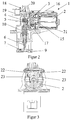
- FIG. 2 shows a side view of the valve unit 1 according to the invention in section.
- the gear unit 3 is a planetary gear, at which by an input shaft 15 which is connected to the drive motor 2 is connected, three non-rotating planet gears 16 are driven, which in turn drive a gear ring gear 17, on the one of the drive motor 2 facing away from the bearing pin 4 with the bearing 5 is.
- a particularly compact design results when the internal gear 17 is arranged in a rotating diametrical magnetic ring, which is known Interacts with a Hall sensor so that the valve lift on can be derived in a simple manner from the rotary movement of the gear ring gear can.
- a cover 18 is shown, which is an alternative to the above Hall sensor can have a sensor unit 19, which is linear in a known manner Adjustment of the valve stroke takes up.
- a connector 20 provided that serves for electrical contacting. This connector 20 can in turn with the sensor unit 19 and via plug contact elements shown in Figure 3 be connected to the drive unit 2 so that the electrical Control of the valve unit 1 is guaranteed.
- a housing 21 of the valve unit 1 is in the area of the drive motor 2 designed as a tunnel housing.
- FIG. 3 shows a sectional view of the drive unit 2 with cover 18.
- the cover 18 has plug-in contact elements 22 which are connected to Deck contact elements 23 of the drive unit 2 cooperate. In this manner and a simple way by mounting the cover 18 electrical contacts are made.
- FIG. 4 shows a sectional view of an exhaust gas recirculation unit according to the invention 24.
- This exhaust gas recirculation unit has a combustion air intake duct section 25 with an exhaust gas introduction section 26 and the valve unit 1.
- the exhaust gas introduction section 26 a Mouth section arranged coaxially with the combustion air intake duct section 25 27 which has a connecting channel arranged transversely to the mouth section 27 28 is connected to a valve channel section 29, which of the Connection channel 28 is cut.
- the connecting channel 28 detects one externally projecting channel extension 30, which is closed by a slug insert 31 is.
- valve channel section 29 has a connecting piece 32 forms for an exhaust gas recirculation line, not shown, the connecting piece 32 has a valve seat 33 which interacts with the valve plate 7 which on the valve rod 6 arranged coaxially to the valve channel section 29 is.
- valve rod 6 in a valve guide bushing 34 is guided, on the one hand in the valve channel section 29 and on the other protrudes into a valve spring chamber 35, the valve rod 6 on the Section which projects into the valve spring chamber 35 and has the guide element 11, acts on the spring element 10, which on the other hand on the valve spring chamber wall 36 is supported.
- valve spring chamber 35 is from Housing 21 is closed to the outside, the housing 21 simultaneously forms the transmission-drive housing and wherein the valve spring chamber 35 through a vent hole, not shown, be connected to the atmosphere can.
- valve guide bush 36 a Dirt chamber 37 has.
Landscapes
- Engineering & Computer Science (AREA)
- General Engineering & Computer Science (AREA)
- Chemical & Material Sciences (AREA)
- Mechanical Engineering (AREA)
- Combustion & Propulsion (AREA)
- Analytical Chemistry (AREA)
- Exhaust-Gas Circulating Devices (AREA)
- Electrically Driven Valve-Operating Means (AREA)
- Mechanically-Actuated Valves (AREA)
Applications Claiming Priority (4)
| Application Number | Priority Date | Filing Date | Title |
|---|---|---|---|
| DE19947971 | 1999-10-05 | ||
| DE19947971A DE19947971A1 (de) | 1999-10-05 | 1999-10-05 | Brennluftansaugkanalabschnitt für Brennkraftmaschinen |
| DE10002577A DE10002577A1 (de) | 2000-01-21 | 2000-01-21 | Elektrisches Stellglied |
| DE10002577 | 2000-01-21 |
Publications (3)
| Publication Number | Publication Date |
|---|---|
| EP1091112A2 true EP1091112A2 (fr) | 2001-04-11 |
| EP1091112A3 EP1091112A3 (fr) | 2001-12-12 |
| EP1091112B1 EP1091112B1 (fr) | 2004-04-21 |
Family
ID=26003966
Family Applications (1)
| Application Number | Title | Priority Date | Filing Date |
|---|---|---|---|
| EP00116817A Expired - Lifetime EP1091112B1 (fr) | 1999-10-05 | 2000-08-04 | Soupape, conduit d'admission d'air et unité de recirculation de gaz d'échappement pour moteurs à combustion |
Country Status (3)
| Country | Link |
|---|---|
| EP (1) | EP1091112B1 (fr) |
| DE (1) | DE50006131D1 (fr) |
| ES (1) | ES2214998T3 (fr) |
Cited By (16)
| Publication number | Priority date | Publication date | Assignee | Title |
|---|---|---|---|---|
| EP1247974A1 (fr) * | 2001-04-06 | 2002-10-09 | Pierburg GmbH | Soupape de remise en circulation de gaz d'échappement |
| DE10125094A1 (de) * | 2001-05-23 | 2002-11-28 | Siemens Ag | Abgasrückführeinrichtung |
| EP1362985A2 (fr) | 2002-05-16 | 2003-11-19 | Pierburg GmbH | Système de soupapes |
| DE10228689A1 (de) * | 2002-06-27 | 2004-01-22 | Conti Temic Microelectronic Gmbh | Verfahren zur Herstellung einer Baugruppe |
| WO2004097184A1 (fr) * | 2003-04-26 | 2004-11-11 | Camcon Ltd | Actionneur electromagnetique |
| DE10336976A1 (de) * | 2003-08-12 | 2005-03-17 | Pierburg Gmbh | Ventilvorrichtung für eine Verbrennungskraftmaschine |
| DE10344218A1 (de) * | 2003-09-22 | 2005-04-14 | Mahle Filtersysteme Gmbh | Abgasrückführungsventil |
| DE10346250A1 (de) * | 2003-10-06 | 2005-05-12 | Bayerische Motoren Werke Ag | Abgaskühler mit einem Bypass |
| WO2011064096A1 (fr) * | 2009-11-24 | 2011-06-03 | Pierbrug Gmbh | Système de vanne pour moteur à combustion interne |
| WO2011067138A1 (fr) * | 2009-12-01 | 2011-06-09 | Pierbrug Gmbh | Ensemble soupape pour moteur à combustion interne |
| DE102010050784A1 (de) * | 2010-11-10 | 2012-05-10 | Pierburg Gmbh | Stellvorrichtung |
| CN102661216A (zh) * | 2012-06-04 | 2012-09-12 | 南岳电控(衡阳)工业技术有限公司 | 柴油发动机废气再循环系统所使用的阀 |
| WO2013021133A1 (fr) | 2011-08-08 | 2013-02-14 | Sonceboz Automotive Sa | Dispositif de dosage compact |
| CN103353007A (zh) * | 2013-06-08 | 2013-10-16 | 高国平 | 气动阀门控制器及其控制方法 |
| DE10362332B4 (de) * | 2003-09-22 | 2014-10-23 | Mahle Filtersysteme Gmbh | Abgasrückführungsventil |
| WO2019101327A1 (fr) | 2017-11-24 | 2019-05-31 | Pierburg Gmbh | Dispositif de soupape comportant une unité de commande pour une position d'ouverture d'une soupape en position de blocage |
Family Cites Families (5)
| Publication number | Priority date | Publication date | Assignee | Title |
|---|---|---|---|---|
| DE3606722A1 (de) * | 1986-03-01 | 1987-09-10 | Sempell Rhein Armaturen | Antrieb, insbesondere zur betaetigung von armaturen mit schnellschalteinrichtung |
| US4840350A (en) * | 1987-07-31 | 1989-06-20 | Bendix Electronics Limited | Electrically actuated EGR valve |
| US5494255A (en) * | 1994-01-12 | 1996-02-27 | Robertshaw Controls Company | Solenoid activated exhaust gas recirculation valve |
| US5704585A (en) * | 1995-08-29 | 1998-01-06 | Siemens Electric Limited | Electrical connection between closure cap and internal actuator of an electrically actuated valve |
| DE19725668C1 (de) * | 1997-06-18 | 1998-10-29 | Daimler Benz Ag | Abgasrückführeinrichtung |
-
2000
- 2000-08-04 ES ES00116817T patent/ES2214998T3/es not_active Expired - Lifetime
- 2000-08-04 DE DE50006131T patent/DE50006131D1/de not_active Expired - Lifetime
- 2000-08-04 EP EP00116817A patent/EP1091112B1/fr not_active Expired - Lifetime
Cited By (27)
| Publication number | Priority date | Publication date | Assignee | Title |
|---|---|---|---|---|
| EP1247974A1 (fr) * | 2001-04-06 | 2002-10-09 | Pierburg GmbH | Soupape de remise en circulation de gaz d'échappement |
| DE10125094A1 (de) * | 2001-05-23 | 2002-11-28 | Siemens Ag | Abgasrückführeinrichtung |
| WO2002095209A1 (fr) * | 2001-05-23 | 2002-11-28 | Siemens Aktiengesellschaft | Dispositif servant a eviter le blocage d'une soupape de remise en circulation de gaz d'echappement apres extinction du moteur a combustion interne |
| US6823854B2 (en) | 2001-05-23 | 2004-11-30 | Siemens Aktiengesellschaft | Device for preventing an exhaust gas recirculation valve from sticking after switching off an internal combustion engine |
| EP1362985A3 (fr) * | 2002-05-16 | 2007-08-29 | Pierburg GmbH | Système de soupapes |
| EP1362985A2 (fr) | 2002-05-16 | 2003-11-19 | Pierburg GmbH | Système de soupapes |
| DE10228689A1 (de) * | 2002-06-27 | 2004-01-22 | Conti Temic Microelectronic Gmbh | Verfahren zur Herstellung einer Baugruppe |
| DE10228689B4 (de) * | 2002-06-27 | 2016-03-17 | Conti Temic Microelectronic Gmbh | Verfahren zur Herstellung einer Baugruppe |
| US7588002B2 (en) | 2003-04-26 | 2009-09-15 | Camcon Ltd. | Programmable high speed valve actuator and power supply therefor |
| WO2004097184A1 (fr) * | 2003-04-26 | 2004-11-11 | Camcon Ltd | Actionneur electromagnetique |
| DE10336976B4 (de) * | 2003-08-12 | 2005-08-18 | Pierburg Gmbh | Ventilvorrichtung für eine Verbrennungskraftmaschine |
| DE10336976A1 (de) * | 2003-08-12 | 2005-03-17 | Pierburg Gmbh | Ventilvorrichtung für eine Verbrennungskraftmaschine |
| DE10344218B4 (de) * | 2003-09-22 | 2014-10-23 | Mahle Filtersysteme Gmbh | Abgasrückführungsventil |
| DE10344218A1 (de) * | 2003-09-22 | 2005-04-14 | Mahle Filtersysteme Gmbh | Abgasrückführungsventil |
| DE10362332B4 (de) * | 2003-09-22 | 2014-10-23 | Mahle Filtersysteme Gmbh | Abgasrückführungsventil |
| DE10346250B4 (de) * | 2003-10-06 | 2018-01-04 | Bayerische Motoren Werke Aktiengesellschaft | Abgaskühler mit einem Bypass |
| DE10346250A1 (de) * | 2003-10-06 | 2005-05-12 | Bayerische Motoren Werke Ag | Abgaskühler mit einem Bypass |
| WO2011064096A1 (fr) * | 2009-11-24 | 2011-06-03 | Pierbrug Gmbh | Système de vanne pour moteur à combustion interne |
| US9016266B2 (en) | 2009-12-01 | 2015-04-28 | Pierburg Gmbh | Valve device for an internal combustion engine |
| WO2011067138A1 (fr) * | 2009-12-01 | 2011-06-09 | Pierbrug Gmbh | Ensemble soupape pour moteur à combustion interne |
| DE102010050784A1 (de) * | 2010-11-10 | 2012-05-10 | Pierburg Gmbh | Stellvorrichtung |
| WO2013021133A1 (fr) | 2011-08-08 | 2013-02-14 | Sonceboz Automotive Sa | Dispositif de dosage compact |
| CN102661216A (zh) * | 2012-06-04 | 2012-09-12 | 南岳电控(衡阳)工业技术有限公司 | 柴油发动机废气再循环系统所使用的阀 |
| CN102661216B (zh) * | 2012-06-04 | 2015-06-03 | 南岳电控(衡阳)工业技术有限公司 | 柴油发动机废气再循环系统所使用的阀 |
| CN103353007A (zh) * | 2013-06-08 | 2013-10-16 | 高国平 | 气动阀门控制器及其控制方法 |
| CN103353007B (zh) * | 2013-06-08 | 2015-09-16 | 宁波市镇海晴鑫石化机械设备有限公司 | 气动阀门控制器及其控制方法 |
| WO2019101327A1 (fr) | 2017-11-24 | 2019-05-31 | Pierburg Gmbh | Dispositif de soupape comportant une unité de commande pour une position d'ouverture d'une soupape en position de blocage |
Also Published As
| Publication number | Publication date |
|---|---|
| EP1091112B1 (fr) | 2004-04-21 |
| ES2214998T3 (es) | 2004-10-01 |
| DE50006131D1 (de) | 2004-05-27 |
| EP1091112A3 (fr) | 2001-12-12 |
Similar Documents
| Publication | Publication Date | Title |
|---|---|---|
| EP1091112B1 (fr) | Soupape, conduit d'admission d'air et unité de recirculation de gaz d'échappement pour moteurs à combustion | |
| EP1115991B1 (fr) | Soupape a clapet | |
| EP2791487B1 (fr) | Dispositif de commande d'une turbine de turbocompresseur à gaz d'échappement | |
| DE60008673T2 (de) | Abgasrückführungsvorrichtung für eine Brennkraftmaschine | |
| EP1826391A2 (fr) | Dispositif de recyclage des gaz d'échappement | |
| DE19510622A1 (de) | Drosselvorrichtung und Verfahren zur Herstellung einer Drosselvorrichtung | |
| DE69504245T2 (de) | Elektromagnetisches Luftregelventil und Rückschlagventil | |
| EP1389272B2 (fr) | Dispositif servant a eviter le blocage d'une soupape de remise en circulation de gaz d'echappement apres extinction du moteur a combustion interne | |
| EP1362985B1 (fr) | Système de soupapes | |
| EP2507498B1 (fr) | Système de vanne pour moteur à combustion interne | |
| DE102007037359A1 (de) | Drosselvorrichtung für ein strömendes Medium | |
| DE102005039926B4 (de) | Vergaser | |
| EP3615787B1 (fr) | Vanne pour un moteur à combustion interne | |
| DE102016123738B4 (de) | Klappenvorrichtung | |
| WO2009053217A1 (fr) | Moteur à combustion interne | |
| DE10126471B4 (de) | Antriebseinrichtung | |
| DE102012205691A1 (de) | Mischventil einer Brennkraftmaschine eines Kraftfahrzeuges | |
| DE19914535A1 (de) | Vorrichtung zur gesteuerten Abgasrückführung in eine Luftzufuhreinrichtung einer Brennkraftmaschine | |
| DE19502907A1 (de) | Elektrisch betriebene Luftgebläseeinheit mit Abschaltventil, insbesondere Sekundärluftgebläseeinheit | |
| DE202015101816U1 (de) | Steuerventil für eine Auspuffanlage und Auspuffanlage mit einem solchen Steuerventil | |
| DE60100768T2 (de) | Abgasrückführvorrichtung für eine Brennkraftmaschine | |
| DE102006033976A1 (de) | Abgasturbolader für eine Brennkraftmaschine | |
| EP3315262B1 (fr) | Outil manuel comprenant un moteur à combustion | |
| DE102004003208A1 (de) | Verdichter im Ansaugtrakt einer Brennkraftmaschine | |
| DE102011011451B4 (de) | Betätigungseinrichtung für einen Abgasturbolader |
Legal Events
| Date | Code | Title | Description |
|---|---|---|---|
| PUAI | Public reference made under article 153(3) epc to a published international application that has entered the european phase |
Free format text: ORIGINAL CODE: 0009012 |
|
| 17P | Request for examination filed |
Effective date: 20000804 |
|
| AK | Designated contracting states |
Kind code of ref document: A2 Designated state(s): AT BE CH CY DE DK ES FI FR GB GR IE IT LI LU MC NL PT SE Kind code of ref document: A2 Designated state(s): CH DE ES FR GB IT LI |
|
| AX | Request for extension of the european patent |
Free format text: AL;LT;LV;MK;RO;SI |
|
| PUAL | Search report despatched |
Free format text: ORIGINAL CODE: 0009013 |
|
| AK | Designated contracting states |
Kind code of ref document: A3 Designated state(s): AT BE CH CY DE DK ES FI FR GB GR IE IT LI LU MC NL PT SE |
|
| AX | Request for extension of the european patent |
Free format text: AL;LT;LV;MK;RO;SI |
|
| RIC1 | Information provided on ipc code assigned before grant |
Free format text: 7F 02M 25/07 A, 7F 16K 31/52 B |
|
| 17Q | First examination report despatched |
Effective date: 20020212 |
|
| RAP1 | Party data changed (applicant data changed or rights of an application transferred) |
Owner name: PIERBURG GMBH |
|
| AKX | Designation fees paid |
Free format text: CH DE ES FR GB IT LI |
|
| GRAP | Despatch of communication of intention to grant a patent |
Free format text: ORIGINAL CODE: EPIDOSNIGR1 |
|
| GRAP | Despatch of communication of intention to grant a patent |
Free format text: ORIGINAL CODE: EPIDOSNIGR1 |
|
| GRAS | Grant fee paid |
Free format text: ORIGINAL CODE: EPIDOSNIGR3 |
|
| GRAA | (expected) grant |
Free format text: ORIGINAL CODE: 0009210 |
|
| AK | Designated contracting states |
Kind code of ref document: B1 Designated state(s): CH DE ES FR GB IT LI |
|
| REG | Reference to a national code |
Ref country code: GB Ref legal event code: FG4D Free format text: NOT ENGLISH |
|
| REG | Reference to a national code |
Ref country code: CH Ref legal event code: NV Representative=s name: E. BLUM & CO. PATENTANWAELTE Ref country code: CH Ref legal event code: EP |
|
| REG | Reference to a national code |
Ref country code: IE Ref legal event code: FG4D Free format text: GERMAN |
|
| REF | Corresponds to: |
Ref document number: 50006131 Country of ref document: DE Date of ref document: 20040527 Kind code of ref document: P |
|
| GBT | Gb: translation of ep patent filed (gb section 77(6)(a)/1977) |
Effective date: 20040901 |
|
| REG | Reference to a national code |
Ref country code: ES Ref legal event code: FG2A Ref document number: 2214998 Country of ref document: ES Kind code of ref document: T3 |
|
| REG | Reference to a national code |
Ref country code: IE Ref legal event code: FD4D |
|
| ET | Fr: translation filed | ||
| PLBI | Opposition filed |
Free format text: ORIGINAL CODE: 0009260 |
|
| PLBQ | Unpublished change to opponent data |
Free format text: ORIGINAL CODE: EPIDOS OPPO |
|
| 26 | Opposition filed |
Opponent name: GUSTAV WAHLER GMBH U. CO. KG Effective date: 20050107 |
|
| PLAX | Notice of opposition and request to file observation + time limit sent |
Free format text: ORIGINAL CODE: EPIDOSNOBS2 |
|
| PLAQ | Examination of admissibility of opposition: information related to despatch of communication + time limit deleted |
Free format text: ORIGINAL CODE: EPIDOSDOPE2 |
|
| PLAR | Examination of admissibility of opposition: information related to receipt of reply deleted |
Free format text: ORIGINAL CODE: EPIDOSDOPE4 |
|
| PLBB | Reply of patent proprietor to notice(s) of opposition received |
Free format text: ORIGINAL CODE: EPIDOSNOBS3 |
|
| PLBQ | Unpublished change to opponent data |
Free format text: ORIGINAL CODE: EPIDOS OPPO |
|
| PLAB | Opposition data, opponent's data or that of the opponent's representative modified |
Free format text: ORIGINAL CODE: 0009299OPPO |
|
| R26 | Opposition filed (corrected) |
Opponent name: GUSTAV WAHLER GMBH U. CO. KG Effective date: 20050107 |
|
| PLBP | Opposition withdrawn |
Free format text: ORIGINAL CODE: 0009264 |
|
| PLBD | Termination of opposition procedure: decision despatched |
Free format text: ORIGINAL CODE: EPIDOSNOPC1 |
|
| PLBM | Termination of opposition procedure: date of legal effect published |
Free format text: ORIGINAL CODE: 0009276 |
|
| STAA | Information on the status of an ep patent application or granted ep patent |
Free format text: STATUS: OPPOSITION PROCEDURE CLOSED |
|
| 27C | Opposition proceedings terminated |
Effective date: 20051204 |
|
| REG | Reference to a national code |
Ref country code: CH Ref legal event code: PFA Owner name: PIERBURG GMBH Free format text: PIERBURG GMBH#ALFRED-PIERBURG-STRASSE 1#41460 NEUSS (DE) -TRANSFER TO- PIERBURG GMBH#ALFRED-PIERBURG-STRASSE 1#41460 NEUSS (DE) |
|
| PGFP | Annual fee paid to national office [announced via postgrant information from national office to epo] |
Ref country code: CH Payment date: 20100825 Year of fee payment: 11 |
|
| PGFP | Annual fee paid to national office [announced via postgrant information from national office to epo] |
Ref country code: GB Payment date: 20100823 Year of fee payment: 11 |
|
| REG | Reference to a national code |
Ref country code: CH Ref legal event code: PL |
|
| GBPC | Gb: european patent ceased through non-payment of renewal fee |
Effective date: 20110804 |
|
| PG25 | Lapsed in a contracting state [announced via postgrant information from national office to epo] |
Ref country code: LI Free format text: LAPSE BECAUSE OF NON-PAYMENT OF DUE FEES Effective date: 20110831 Ref country code: CH Free format text: LAPSE BECAUSE OF NON-PAYMENT OF DUE FEES Effective date: 20110831 |
|
| PG25 | Lapsed in a contracting state [announced via postgrant information from national office to epo] |
Ref country code: GB Free format text: LAPSE BECAUSE OF NON-PAYMENT OF DUE FEES Effective date: 20110804 |
|
| REG | Reference to a national code |
Ref country code: FR Ref legal event code: PLFP Year of fee payment: 17 |
|
| REG | Reference to a national code |
Ref country code: FR Ref legal event code: PLFP Year of fee payment: 18 |
|
| REG | Reference to a national code |
Ref country code: FR Ref legal event code: PLFP Year of fee payment: 19 |
|
| PGFP | Annual fee paid to national office [announced via postgrant information from national office to epo] |
Ref country code: DE Payment date: 20190822 Year of fee payment: 20 Ref country code: IT Payment date: 20190821 Year of fee payment: 20 Ref country code: FR Payment date: 20190822 Year of fee payment: 20 Ref country code: ES Payment date: 20190919 Year of fee payment: 20 |
|
| REG | Reference to a national code |
Ref country code: DE Ref legal event code: R082 Ref document number: 50006131 Country of ref document: DE Representative=s name: TERPATENT PATENTANWAELTE TER SMITTEN EBERLEIN-, DE |
|
| REG | Reference to a national code |
Ref country code: DE Ref legal event code: R071 Ref document number: 50006131 Country of ref document: DE |
|
| REG | Reference to a national code |
Ref country code: ES Ref legal event code: FD2A Effective date: 20201201 |
|
| PG25 | Lapsed in a contracting state [announced via postgrant information from national office to epo] |
Ref country code: ES Free format text: LAPSE BECAUSE OF EXPIRATION OF PROTECTION Effective date: 20200805 |