EP1362985A2 - Système de soupapes - Google Patents
Système de soupapes Download PDFInfo
- Publication number
- EP1362985A2 EP1362985A2 EP03002950A EP03002950A EP1362985A2 EP 1362985 A2 EP1362985 A2 EP 1362985A2 EP 03002950 A EP03002950 A EP 03002950A EP 03002950 A EP03002950 A EP 03002950A EP 1362985 A2 EP1362985 A2 EP 1362985A2
- Authority
- EP
- European Patent Office
- Prior art keywords
- valve
- eccentric
- valve system
- coupling
- unit
- Prior art date
- Legal status (The legal status is an assumption and is not a legal conclusion. Google has not performed a legal analysis and makes no representation as to the accuracy of the status listed.)
- Granted
Links
- 230000008878 coupling Effects 0.000 claims abstract description 33
- 238000010168 coupling process Methods 0.000 claims abstract description 33
- 238000005859 coupling reaction Methods 0.000 claims abstract description 33
- 238000002485 combustion reaction Methods 0.000 claims description 6
- 238000001816 cooling Methods 0.000 claims description 3
- XLYOFNOQVPJJNP-UHFFFAOYSA-N water Substances O XLYOFNOQVPJJNP-UHFFFAOYSA-N 0.000 claims description 3
- 238000009434 installation Methods 0.000 description 3
- 238000005096 rolling process Methods 0.000 description 3
- FYYHWMGAXLPEAU-UHFFFAOYSA-N Magnesium Chemical compound [Mg] FYYHWMGAXLPEAU-UHFFFAOYSA-N 0.000 description 2
- 229910052749 magnesium Inorganic materials 0.000 description 2
- 239000011777 magnesium Substances 0.000 description 2
- 238000010276 construction Methods 0.000 description 1
- 238000011156 evaluation Methods 0.000 description 1
- 238000004519 manufacturing process Methods 0.000 description 1
Images

Classifications
-
- F—MECHANICAL ENGINEERING; LIGHTING; HEATING; WEAPONS; BLASTING
- F01—MACHINES OR ENGINES IN GENERAL; ENGINE PLANTS IN GENERAL; STEAM ENGINES
- F01L—CYCLICALLY OPERATING VALVES FOR MACHINES OR ENGINES
- F01L1/00—Valve-gear or valve arrangements, e.g. lift-valve gear
- F01L1/12—Transmitting gear between valve drive and valve
-
- F—MECHANICAL ENGINEERING; LIGHTING; HEATING; WEAPONS; BLASTING
- F01—MACHINES OR ENGINES IN GENERAL; ENGINE PLANTS IN GENERAL; STEAM ENGINES
- F01L—CYCLICALLY OPERATING VALVES FOR MACHINES OR ENGINES
- F01L1/00—Valve-gear or valve arrangements, e.g. lift-valve gear
- F01L1/02—Valve drive
- F01L1/04—Valve drive by means of cams, camshafts, cam discs, eccentrics or the like
- F01L1/047—Camshafts
- F01L1/053—Camshafts overhead type
-
- F—MECHANICAL ENGINEERING; LIGHTING; HEATING; WEAPONS; BLASTING
- F01—MACHINES OR ENGINES IN GENERAL; ENGINE PLANTS IN GENERAL; STEAM ENGINES
- F01L—CYCLICALLY OPERATING VALVES FOR MACHINES OR ENGINES
- F01L1/00—Valve-gear or valve arrangements, e.g. lift-valve gear
- F01L1/26—Valve-gear or valve arrangements, e.g. lift-valve gear characterised by the provision of two or more valves operated simultaneously by same transmitting-gear; peculiar to machines or engines with more than two lift-valves per cylinder
-
- F—MECHANICAL ENGINEERING; LIGHTING; HEATING; WEAPONS; BLASTING
- F01—MACHINES OR ENGINES IN GENERAL; ENGINE PLANTS IN GENERAL; STEAM ENGINES
- F01L—CYCLICALLY OPERATING VALVES FOR MACHINES OR ENGINES
- F01L1/00—Valve-gear or valve arrangements, e.g. lift-valve gear
- F01L1/34—Valve-gear or valve arrangements, e.g. lift-valve gear characterised by the provision of means for changing the timing of the valves without changing the duration of opening and without affecting the magnitude of the valve lift
- F01L1/344—Valve-gear or valve arrangements, e.g. lift-valve gear characterised by the provision of means for changing the timing of the valves without changing the duration of opening and without affecting the magnitude of the valve lift changing the angular relationship between crankshaft and camshaft, e.g. using helicoidal gear
- F01L1/352—Valve-gear or valve arrangements, e.g. lift-valve gear characterised by the provision of means for changing the timing of the valves without changing the duration of opening and without affecting the magnitude of the valve lift changing the angular relationship between crankshaft and camshaft, e.g. using helicoidal gear using bevel or epicyclic gear
-
- F—MECHANICAL ENGINEERING; LIGHTING; HEATING; WEAPONS; BLASTING
- F01—MACHINES OR ENGINES IN GENERAL; ENGINE PLANTS IN GENERAL; STEAM ENGINES
- F01L—CYCLICALLY OPERATING VALVES FOR MACHINES OR ENGINES
- F01L3/00—Lift-valve, i.e. cut-off apparatus with closure members having at least a component of their opening and closing motion perpendicular to the closing faces; Parts or accessories thereof
- F01L3/10—Connecting springs to valve members
-
- F—MECHANICAL ENGINEERING; LIGHTING; HEATING; WEAPONS; BLASTING
- F01—MACHINES OR ENGINES IN GENERAL; ENGINE PLANTS IN GENERAL; STEAM ENGINES
- F01L—CYCLICALLY OPERATING VALVES FOR MACHINES OR ENGINES
- F01L9/00—Valve-gear or valve arrangements actuated non-mechanically
- F01L9/20—Valve-gear or valve arrangements actuated non-mechanically by electric means
- F01L9/22—Valve-gear or valve arrangements actuated non-mechanically by electric means actuated by rotary motors
-
- F—MECHANICAL ENGINEERING; LIGHTING; HEATING; WEAPONS; BLASTING
- F02—COMBUSTION ENGINES; HOT-GAS OR COMBUSTION-PRODUCT ENGINE PLANTS
- F02M—SUPPLYING COMBUSTION ENGINES IN GENERAL WITH COMBUSTIBLE MIXTURES OR CONSTITUENTS THEREOF
- F02M26/00—Engine-pertinent apparatus for adding exhaust gases to combustion-air, main fuel or fuel-air mixture, e.g. by exhaust gas recirculation [EGR] systems
- F02M26/13—Arrangement or layout of EGR passages, e.g. in relation to specific engine parts or for incorporation of accessories
- F02M26/38—Arrangement or layout of EGR passages, e.g. in relation to specific engine parts or for incorporation of accessories with two or more EGR valves disposed in parallel
-
- F—MECHANICAL ENGINEERING; LIGHTING; HEATING; WEAPONS; BLASTING
- F02—COMBUSTION ENGINES; HOT-GAS OR COMBUSTION-PRODUCT ENGINE PLANTS
- F02M—SUPPLYING COMBUSTION ENGINES IN GENERAL WITH COMBUSTIBLE MIXTURES OR CONSTITUENTS THEREOF
- F02M26/00—Engine-pertinent apparatus for adding exhaust gases to combustion-air, main fuel or fuel-air mixture, e.g. by exhaust gas recirculation [EGR] systems
- F02M26/52—Systems for actuating EGR valves
- F02M26/53—Systems for actuating EGR valves using electric actuators, e.g. solenoids
- F02M26/54—Rotary actuators, e.g. step motors
-
- F—MECHANICAL ENGINEERING; LIGHTING; HEATING; WEAPONS; BLASTING
- F02—COMBUSTION ENGINES; HOT-GAS OR COMBUSTION-PRODUCT ENGINE PLANTS
- F02M—SUPPLYING COMBUSTION ENGINES IN GENERAL WITH COMBUSTIBLE MIXTURES OR CONSTITUENTS THEREOF
- F02M26/00—Engine-pertinent apparatus for adding exhaust gases to combustion-air, main fuel or fuel-air mixture, e.g. by exhaust gas recirculation [EGR] systems
- F02M26/65—Constructional details of EGR valves
- F02M26/66—Lift valves, e.g. poppet valves
- F02M26/67—Pintles; Spindles; Springs; Bearings; Sealings; Connections to actuators
-
- F—MECHANICAL ENGINEERING; LIGHTING; HEATING; WEAPONS; BLASTING
- F02—COMBUSTION ENGINES; HOT-GAS OR COMBUSTION-PRODUCT ENGINE PLANTS
- F02M—SUPPLYING COMBUSTION ENGINES IN GENERAL WITH COMBUSTIBLE MIXTURES OR CONSTITUENTS THEREOF
- F02M26/00—Engine-pertinent apparatus for adding exhaust gases to combustion-air, main fuel or fuel-air mixture, e.g. by exhaust gas recirculation [EGR] systems
- F02M26/65—Constructional details of EGR valves
- F02M26/66—Lift valves, e.g. poppet valves
- F02M26/69—Lift valves, e.g. poppet valves having two or more valve-closing members
-
- F—MECHANICAL ENGINEERING; LIGHTING; HEATING; WEAPONS; BLASTING
- F01—MACHINES OR ENGINES IN GENERAL; ENGINE PLANTS IN GENERAL; STEAM ENGINES
- F01L—CYCLICALLY OPERATING VALVES FOR MACHINES OR ENGINES
- F01L1/00—Valve-gear or valve arrangements, e.g. lift-valve gear
- F01L1/30—Valve-gear or valve arrangements, e.g. lift-valve gear characterised by the provision of positively opened and closed valves, i.e. desmodromic valves
-
- F—MECHANICAL ENGINEERING; LIGHTING; HEATING; WEAPONS; BLASTING
- F01—MACHINES OR ENGINES IN GENERAL; ENGINE PLANTS IN GENERAL; STEAM ENGINES
- F01L—CYCLICALLY OPERATING VALVES FOR MACHINES OR ENGINES
- F01L2301/00—Using particular materials
-
- F—MECHANICAL ENGINEERING; LIGHTING; HEATING; WEAPONS; BLASTING
- F01—MACHINES OR ENGINES IN GENERAL; ENGINE PLANTS IN GENERAL; STEAM ENGINES
- F01L—CYCLICALLY OPERATING VALVES FOR MACHINES OR ENGINES
- F01L2305/00—Valve arrangements comprising rollers
-
- F—MECHANICAL ENGINEERING; LIGHTING; HEATING; WEAPONS; BLASTING
- F01—MACHINES OR ENGINES IN GENERAL; ENGINE PLANTS IN GENERAL; STEAM ENGINES
- F01L—CYCLICALLY OPERATING VALVES FOR MACHINES OR ENGINES
- F01L2800/00—Methods of operation using a variable valve timing mechanism
- F01L2800/10—Providing exhaust gas recirculation [EGR]
-
- F—MECHANICAL ENGINEERING; LIGHTING; HEATING; WEAPONS; BLASTING
- F02—COMBUSTION ENGINES; HOT-GAS OR COMBUSTION-PRODUCT ENGINE PLANTS
- F02M—SUPPLYING COMBUSTION ENGINES IN GENERAL WITH COMBUSTIBLE MIXTURES OR CONSTITUENTS THEREOF
- F02M26/00—Engine-pertinent apparatus for adding exhaust gases to combustion-air, main fuel or fuel-air mixture, e.g. by exhaust gas recirculation [EGR] systems
- F02M26/13—Arrangement or layout of EGR passages, e.g. in relation to specific engine parts or for incorporation of accessories
- F02M26/42—Arrangement or layout of EGR passages, e.g. in relation to specific engine parts or for incorporation of accessories having two or more EGR passages; EGR systems specially adapted for engines having two or more cylinders
-
- F—MECHANICAL ENGINEERING; LIGHTING; HEATING; WEAPONS; BLASTING
- F02—COMBUSTION ENGINES; HOT-GAS OR COMBUSTION-PRODUCT ENGINE PLANTS
- F02M—SUPPLYING COMBUSTION ENGINES IN GENERAL WITH COMBUSTIBLE MIXTURES OR CONSTITUENTS THEREOF
- F02M26/00—Engine-pertinent apparatus for adding exhaust gases to combustion-air, main fuel or fuel-air mixture, e.g. by exhaust gas recirculation [EGR] systems
- F02M26/65—Constructional details of EGR valves
- F02M26/72—Housings
- F02M26/73—Housings with means for heating or cooling the EGR valve
Definitions
- the invention relates in particular to a valve system for internal combustion engines for exhaust gas recirculation with at least one housing in which a drive unit with a drive shaft, an eccentrically driven clutch unit and at least a valve is arranged, the valve comprising at least one valve rod, a valve closing body and a valve seat, the coupling unit the rotational movement of the drive unit in a linear movement of the valve rods transforms.
- Such a valve system has in essentially a drive unit, a gear unit with a pin eccentrically arranged bearings as coupling parts and a valve with valve rod, Valve closing member and valve seat, the gear unit with the valve rod in There is an active connection and can thus open or close the valve. Furthermore it has an outlet opening and an inlet opening.
- the object of the invention is to create a valve system create, which avoids the disadvantages mentioned above and is also easy to set up and is inexpensive to manufacture.
- the coupling unit advantageously consists of a through the drive shaft eccentrically driven coupling element and at least two fixed to the coupling element connected coupling strands, the coupling strands each from a first eccentric, a connecting shaft arranged in a bearing, that at its first end with the first eccentric and at its second end with a second eccentric is firmly connected and one is fixed to the second eccentric connected bearing element exist.
- a valve system designed in this way therefore requires several valves to be actuated only one drive unit and possibly a sensor unit. Furthermore only one housing is required for the valves, so that the entire valve system pre-assembled on the intake line or the exhaust lines can. This reduces both the mechanical and the electrical assembly effort considerably, which in addition to the reduced component costs also a There is a reduction in assembly costs.
- valves depending on the angular position of the first to the second eccentric of a clutch train either synchronously, that is simultaneous opening and closing of the valves, especially in internal combustion engines V-shaped or asynchronous, i.e. opening and closing at different times of the valves to operate. This creates a variety of installation options for a created such a valve system.
- a particularly simple form of mounting the connecting shaft of the two eccentrics is created in that the bearing with the housing of the valve system connected is.
- the roller bearings are advantageously arranged in scenes that with the valve rods are firmly connected, so that positive guidance of the valve rods arises.
- valve system When this valve system is attached to suction pipes made of plastic or magnesium water cooling can be integrated into the housing.
- valve system is created which is simple and is built robustly and also saves weight. Furthermore one reaches one high flexibility with regard to installation and pre-assembly. Due to the forced control the valves can also be actively closed and locked.
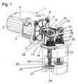
- Figure 1 shows a perspective view of a valve system according to the invention with cut housing and without housing cover.
- Figure 2 shows a perspective view of the valve system without a drive unit and without housing cover with cut housing.
- Figure 3 shows a perspective view of a section of the valve system without Housing cover and here in particular a coupling unit according to the invention and a backdrop for forced guidance, with arrows to show the direction of movement of the individual components of the coupling device.
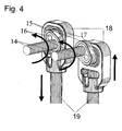
- Figure 4 shows a perspective view of an output part of the clutch unit asynchronous operation.
- the valve system shown consists of a drive unit 1, which one Electric motor 2 with a planetary gear 3 and one from a motor housing 4 emerging drive shaft 5 there.
- a drive unit 1 On the end of the from the engine case 4 emerging drive shaft 5 is an eccentrically arranged driver 6 firmly attached, which in turn via a pin 7 with a coupling element 8, which is perpendicular to the drive shaft 5, is rotatably connected.
- the rotary motion the drive shaft 5 is on this coupling element on two identical coupling strands 9 transferred.
- the eccentrically arranged driver 6, the pin 7, the Coupling element 8 and the two coupling strands 9 form a coupling unit 10.
- Each of the two coupling strands 9 consists of a first eccentric 11, the is in turn connected to the coupling element 8 via a pin 12, as well as one in a bearing 13 which is fixedly mounted with respect to the drive shaft 5 Connecting shaft 14, the first eccentric 11 with a second eccentric 15 connects.
- This second eccentric 15 is in turn connected to a pin 16 a bearing element, in this case a roller bearing 17.
- This roller bearing 17 simultaneously forms the end member of the coupling unit 10 or the two Coupling strands 9.
- the two roller bearings 17 are each arranged in a link 18, the movement of the coupling unit 10 or the rolling bearing 17 on two Valve rods 19, which are simultaneously positively guided by the backdrop 18, transmits.
- FIG. 3 shows the individual directions of movement of the components of the coupling unit 10 represented again by arrows.
- the rotary motion the drive shaft 5 by the eccentrically arranged driver 6 in essentially converted into a horizontal movement of the coupling element 8.
- This transmits this movement to the roller bearing 17, from which a essential vertical movement of the scenes 18 and thus the fixed with the scenes connected valve rods 19 arises.
- two valve plates 20 which are fixedly connected to the valve rods 19 against their Valve seats 21, which are part of a housing part 22, pressed.
- valve plate 20 By moving the Drive shaft 5 in the opposite direction, the valve plate from the valve seat 21 lifted off, whereby a fluidic connection between the outlet opening 23 and Inlet opening 24 is made.
- a spring element 25 is provided, which the valve rod 19 in the direction of Bearing 17 holds under bias. This pre-tension arises through the introduction of the spring element 25 between a support surface 26 of the housing part 22 and a support ring 27, which is either part of the backdrop 18, or as in the embodiment is a spring plate arranged under the backdrop 18.
- the support ring 27 of the backdrop 18 In the event of a failure of the electric motor 2 is the support ring 27 of the backdrop 18 in the direction of Rolling bearing 17 loaded by the force of the spring element 25 and thus the valve plate 20 pressed against the valve seat 21 via the valve rod 19.
- the housing part 22 is constructed so that it is not only the valve seat 21, the outlet opening 23, the inlet opening 24 and the bearing surface 26 for the spring element 25 includes, but also has two bearing receiving base 28, which Bearing 13 of the connecting shafts 14.
- the entire valve system is closed by a housing cover, not shown in the drawings.
- the valves can vary depending on Position of the first eccentric 11 in relation to the second eccentric 15 either synchronously, which is particularly useful for V-shaped internal combustion engines, or as shown in Figure 4 are operated asynchronously.
- the second eccentric 15 one coupling strand 9 by 180 ° compared to the eccentric 15 of the other Coupling strand rotated, causing an opposite movement of the two Valve rods 19 are formed.
- every angular position is the two eccentrics 15 conceivable to each other.
- a water cooling can advantageously be integrated into the housing, which makes it possible to use this valve on intake manifolds when used as an exhaust gas recirculation valve made of plastic or magnesium.
Landscapes
- Engineering & Computer Science (AREA)
- Mechanical Engineering (AREA)
- General Engineering & Computer Science (AREA)
- Chemical & Material Sciences (AREA)
- Combustion & Propulsion (AREA)
- Mechanically-Actuated Valves (AREA)
- Multiple-Way Valves (AREA)
Applications Claiming Priority (2)
| Application Number | Priority Date | Filing Date | Title |
|---|---|---|---|
| DE10221711 | 2002-05-16 | ||
| DE10221711A DE10221711A1 (de) | 2002-05-16 | 2002-05-16 | Ventilsystem |
Publications (3)
| Publication Number | Publication Date |
|---|---|
| EP1362985A2 true EP1362985A2 (fr) | 2003-11-19 |
| EP1362985A3 EP1362985A3 (fr) | 2007-08-29 |
| EP1362985B1 EP1362985B1 (fr) | 2009-11-25 |
Family
ID=29265314
Family Applications (1)
| Application Number | Title | Priority Date | Filing Date |
|---|---|---|---|
| EP03002950A Expired - Lifetime EP1362985B1 (fr) | 2002-05-16 | 2003-02-11 | Système de soupapes |
Country Status (3)
| Country | Link |
|---|---|
| EP (1) | EP1362985B1 (fr) |
| DE (2) | DE10221711A1 (fr) |
| ES (1) | ES2335873T3 (fr) |
Cited By (9)
| Publication number | Priority date | Publication date | Assignee | Title |
|---|---|---|---|---|
| EP1793113A3 (fr) * | 2005-12-02 | 2008-10-15 | Behr Thermot-tronik GmbH | Vanne double pour dispositif de recyclage des gaz d'échappement |
| EP1793114A3 (fr) * | 2005-12-02 | 2008-10-15 | Behr Thermot-tronik GmbH | Appareil, en particulier vanne de recyclage des gaz d'échappement, pour commander un courant de fluide |
| WO2011067138A1 (fr) * | 2009-12-01 | 2011-06-09 | Pierbrug Gmbh | Ensemble soupape pour moteur à combustion interne |
| EP2133549A3 (fr) * | 2008-06-10 | 2011-06-29 | Pierburg GmbH | Système d'aération |
| EP2027369B1 (fr) * | 2006-05-18 | 2012-08-15 | Institut für Automatisierung und Informatik GmbH | Dispositif électromoteur utilisé dans des soupapes d'échange des gaz |
| WO2013076412A1 (fr) * | 2011-11-25 | 2013-05-30 | Valeo Systemes De Controle Moteur | Vanne de controle pour systeme de recirculation des gaz d'echappement d'un moteur a combustion interne |
| DE102013206481A1 (de) * | 2013-04-11 | 2014-10-16 | Mahle International Gmbh | Ventileinrichtung |
| WO2015014660A1 (fr) * | 2013-08-01 | 2015-02-05 | Continental Automotive Gmbh | Dispositif pour commander un refroidisseur d'air de suralimentation disposé dans un canal d'aspiration d'un moteur à combustion interne et procédé pour faire fonctionner un tel dispositif |
| WO2017060022A1 (fr) * | 2015-10-05 | 2017-04-13 | Pierburg Gmbh | Soupape pour moteur à combustion interne |
Families Citing this family (8)
| Publication number | Priority date | Publication date | Assignee | Title |
|---|---|---|---|---|
| DE102008005591A1 (de) | 2008-01-22 | 2009-07-23 | Bayerische Motoren Werke Aktiengesellschaft | Ventileinrichtung für eine Abgasrückführungseinrichtung |
| DE102008030785B4 (de) | 2008-06-28 | 2012-10-31 | Pierburg Gmbh | Abgasrückführvorrichtung für eine Verbrennungskraftmaschine |
| DE102009036284A1 (de) | 2009-08-06 | 2011-02-24 | Pierburg Gmbh | Ventilvorrichtung für eine Verbrennungskraftmaschine |
| DE102009053428A1 (de) | 2009-11-19 | 2011-06-09 | Pierburg Gmbh | Stellvorrichtung zur Umwandlung einer rotatorischen Bewegung in eine lineare Bewegung |
| DE102010006037B4 (de) | 2010-01-27 | 2013-01-17 | Pierburg Gmbh | Ventilvorrichtung für eine Verbrennungskraftmaschine |
| DE102010050784A1 (de) * | 2010-11-10 | 2012-05-10 | Pierburg Gmbh | Stellvorrichtung |
| CN103939170A (zh) * | 2014-03-07 | 2014-07-23 | 同济大学 | 一种用于二冲程自由活塞发动机-发电机系统的可控气门机构 |
| DE102014117309B4 (de) | 2014-11-26 | 2021-02-04 | Pierburg Gmbh | Ventilvorrichtung zur Abgasrückführung an einem Verbrennungsmotor |
Citations (3)
| Publication number | Priority date | Publication date | Assignee | Title |
|---|---|---|---|---|
| US4027636A (en) | 1975-05-26 | 1977-06-07 | Nissan Motor Co., Ltd. | Flow rate control apparatus in exhaust gas recirculation system |
| EP0971113A2 (fr) | 1998-07-06 | 2000-01-12 | Eaton Corporation | Système de recyclage des gaz d'échappement avec logique de commande améliorée |
| EP1091112A2 (fr) | 1999-10-05 | 2001-04-11 | Pierburg Aktiengesellschaft | Soupape, conduit d'admission d'air et unité de recirculation de gaz d'échappement pour moteurs à combustion |
Family Cites Families (2)
| Publication number | Priority date | Publication date | Assignee | Title |
|---|---|---|---|---|
| DE19948379B4 (de) * | 1999-10-07 | 2009-11-05 | Linde Material Handling Gmbh | Hydraulisches Steuerventil |
| JP3597453B2 (ja) * | 2000-09-22 | 2004-12-08 | 株式会社市丸技研 | 直動形電動バルブ |
-
2002
- 2002-05-16 DE DE10221711A patent/DE10221711A1/de not_active Withdrawn
-
2003
- 2003-02-11 ES ES03002950T patent/ES2335873T3/es not_active Expired - Lifetime
- 2003-02-11 DE DE50312149T patent/DE50312149D1/de not_active Expired - Lifetime
- 2003-02-11 EP EP03002950A patent/EP1362985B1/fr not_active Expired - Lifetime
Patent Citations (3)
| Publication number | Priority date | Publication date | Assignee | Title |
|---|---|---|---|---|
| US4027636A (en) | 1975-05-26 | 1977-06-07 | Nissan Motor Co., Ltd. | Flow rate control apparatus in exhaust gas recirculation system |
| EP0971113A2 (fr) | 1998-07-06 | 2000-01-12 | Eaton Corporation | Système de recyclage des gaz d'échappement avec logique de commande améliorée |
| EP1091112A2 (fr) | 1999-10-05 | 2001-04-11 | Pierburg Aktiengesellschaft | Soupape, conduit d'admission d'air et unité de recirculation de gaz d'échappement pour moteurs à combustion |
Cited By (12)
| Publication number | Priority date | Publication date | Assignee | Title |
|---|---|---|---|---|
| EP1793113A3 (fr) * | 2005-12-02 | 2008-10-15 | Behr Thermot-tronik GmbH | Vanne double pour dispositif de recyclage des gaz d'échappement |
| EP1793114A3 (fr) * | 2005-12-02 | 2008-10-15 | Behr Thermot-tronik GmbH | Appareil, en particulier vanne de recyclage des gaz d'échappement, pour commander un courant de fluide |
| EP2027369B1 (fr) * | 2006-05-18 | 2012-08-15 | Institut für Automatisierung und Informatik GmbH | Dispositif électromoteur utilisé dans des soupapes d'échange des gaz |
| EP2133549A3 (fr) * | 2008-06-10 | 2011-06-29 | Pierburg GmbH | Système d'aération |
| WO2011067138A1 (fr) * | 2009-12-01 | 2011-06-09 | Pierbrug Gmbh | Ensemble soupape pour moteur à combustion interne |
| US9016266B2 (en) | 2009-12-01 | 2015-04-28 | Pierburg Gmbh | Valve device for an internal combustion engine |
| WO2013076412A1 (fr) * | 2011-11-25 | 2013-05-30 | Valeo Systemes De Controle Moteur | Vanne de controle pour systeme de recirculation des gaz d'echappement d'un moteur a combustion interne |
| FR2983252A1 (fr) * | 2011-11-25 | 2013-05-31 | Valeo Sys Controle Moteur Sas | Vanne de controle pour systeme de recirculation des gaz d'echappement d'un moteur a combustion interne |
| US9217395B2 (en) | 2011-11-25 | 2015-12-22 | Valeo Systemes De Controle Moteur | Control valve for an internal combustion engine exhaust gas recirculation system |
| DE102013206481A1 (de) * | 2013-04-11 | 2014-10-16 | Mahle International Gmbh | Ventileinrichtung |
| WO2015014660A1 (fr) * | 2013-08-01 | 2015-02-05 | Continental Automotive Gmbh | Dispositif pour commander un refroidisseur d'air de suralimentation disposé dans un canal d'aspiration d'un moteur à combustion interne et procédé pour faire fonctionner un tel dispositif |
| WO2017060022A1 (fr) * | 2015-10-05 | 2017-04-13 | Pierburg Gmbh | Soupape pour moteur à combustion interne |
Also Published As
| Publication number | Publication date |
|---|---|
| EP1362985B1 (fr) | 2009-11-25 |
| ES2335873T3 (es) | 2010-04-06 |
| DE50312149D1 (de) | 2010-01-07 |
| DE10221711A1 (de) | 2003-11-27 |
| EP1362985A3 (fr) | 2007-08-29 |
Similar Documents
| Publication | Publication Date | Title |
|---|---|---|
| EP1362985B1 (fr) | Système de soupapes | |
| EP2577004B1 (fr) | Dispositif de reglage d'arbre a cames a actionnement hydraulique | |
| EP2951402B1 (fr) | Turbocompresseur à gaz d'échappement présentant une connection sans usure des composants du system wastegate | |
| EP0725210B1 (fr) | Module d'aspiration | |
| EP2313583B1 (fr) | Unité d'entraînement comprenant un élément fonctionnel bloqué pour système de verrouillage centralisé | |
| EP1091112B1 (fr) | Soupape, conduit d'admission d'air et unité de recirculation de gaz d'échappement pour moteurs à combustion | |
| DE102017222465A1 (de) | Klappeneinrichtung für den Abgasstrang eines Verbrennungsmotors | |
| EP1457645A1 (fr) | Mécanisme de commande de soupapes pour moteur à combustion interne | |
| DE102018112815A1 (de) | Variabler Ventiltrieb einer Hubkolbenbrennkraftmaschine | |
| EP3615787B1 (fr) | Vanne pour un moteur à combustion interne | |
| EP1319831B1 (fr) | Pompe à combustible haute pression avec pompe de gavage à pallettes | |
| DE19706769B4 (de) | Ventilsteuervorrichtung für eine Brennkraftmaschine | |
| DE102017130323B3 (de) | Ventilvorrichtung für eine Verbrennungskraftmaschine | |
| DE102005024205A1 (de) | Lufteinlassteuervorrichtung mit einer Dehnungsabsorptionsstruktur | |
| DE102009039911A1 (de) | Umströmungseinrichtung für eine Aufladevorrichtung | |
| EP3014080A1 (fr) | Système de ressorts pour commande de soupape variable de moteur à combustion interne | |
| DE102009043627A1 (de) | Ansaugeinrichtung für Verbrennungsmotoren | |
| EP2771564A1 (fr) | Dispositif à levier et injecteur | |
| EP1896706B1 (fr) | Systeme de volet pour installation de gaz d'affinage | |
| DE102009053428A1 (de) | Stellvorrichtung zur Umwandlung einer rotatorischen Bewegung in eine lineare Bewegung | |
| WO2004085805A1 (fr) | Dispositif permettant de faire fonctionner des soupapes d'echange des gaz dans des moteurs alternatifs a pistons | |
| EP0663515B1 (fr) | Dispositif de compensation du jeu des soupapes | |
| EP2133549A2 (fr) | Système d'aération | |
| DE102004002196B3 (de) | Vorrichtung und Verfahren zur Kolbenmontage | |
| WO2012110212A1 (fr) | Dispositif d'actionnement pour un turbocompresseur à gaz d'échappement |
Legal Events
| Date | Code | Title | Description |
|---|---|---|---|
| PUAI | Public reference made under article 153(3) epc to a published international application that has entered the european phase |
Free format text: ORIGINAL CODE: 0009012 |
|
| 17P | Request for examination filed |
Effective date: 20030211 |
|
| AK | Designated contracting states |
Kind code of ref document: A2 Designated state(s): AT BE BG CH CY CZ DE DK EE ES FI FR GB GR HU IE IT LI LU MC NL PT SE SI SK TR |
|
| AX | Request for extension of the european patent |
Extension state: AL LT LV MK RO |
|
| PUAL | Search report despatched |
Free format text: ORIGINAL CODE: 0009013 |
|
| AK | Designated contracting states |
Kind code of ref document: A3 Designated state(s): AT BE BG CH CY CZ DE DK EE ES FI FR GB GR HU IE IT LI LU MC NL PT SE SI SK TR |
|
| AX | Request for extension of the european patent |
Extension state: AL LT LV MK RO |
|
| 17Q | First examination report despatched |
Effective date: 20071123 |
|
| AKX | Designation fees paid |
Designated state(s): DE ES FR GB IT |
|
| GRAP | Despatch of communication of intention to grant a patent |
Free format text: ORIGINAL CODE: EPIDOSNIGR1 |
|
| GRAS | Grant fee paid |
Free format text: ORIGINAL CODE: EPIDOSNIGR3 |
|
| GRAA | (expected) grant |
Free format text: ORIGINAL CODE: 0009210 |
|
| AK | Designated contracting states |
Kind code of ref document: B1 Designated state(s): DE ES FR GB IT |
|
| REG | Reference to a national code |
Ref country code: GB Ref legal event code: FG4D Free format text: NOT ENGLISH |
|
| REF | Corresponds to: |
Ref document number: 50312149 Country of ref document: DE Date of ref document: 20100107 Kind code of ref document: P |
|
| REG | Reference to a national code |
Ref country code: ES Ref legal event code: FG2A Ref document number: 2335873 Country of ref document: ES Kind code of ref document: T3 |
|
| PGFP | Annual fee paid to national office [announced via postgrant information from national office to epo] |
Ref country code: ES Payment date: 20100219 Year of fee payment: 8 |
|
| PGFP | Annual fee paid to national office [announced via postgrant information from national office to epo] |
Ref country code: FR Payment date: 20100315 Year of fee payment: 8 Ref country code: IT Payment date: 20100226 Year of fee payment: 8 |
|
| PGFP | Annual fee paid to national office [announced via postgrant information from national office to epo] |
Ref country code: GB Payment date: 20100219 Year of fee payment: 8 |
|
| PLBE | No opposition filed within time limit |
Free format text: ORIGINAL CODE: 0009261 |
|
| STAA | Information on the status of an ep patent application or granted ep patent |
Free format text: STATUS: NO OPPOSITION FILED WITHIN TIME LIMIT |
|
| 26N | No opposition filed |
Effective date: 20100826 |
|
| GBPC | Gb: european patent ceased through non-payment of renewal fee |
Effective date: 20110211 |
|
| REG | Reference to a national code |
Ref country code: FR Ref legal event code: ST Effective date: 20111102 |
|
| PG25 | Lapsed in a contracting state [announced via postgrant information from national office to epo] |
Ref country code: IT Free format text: LAPSE BECAUSE OF NON-PAYMENT OF DUE FEES Effective date: 20110211 |
|
| PG25 | Lapsed in a contracting state [announced via postgrant information from national office to epo] |
Ref country code: FR Free format text: LAPSE BECAUSE OF NON-PAYMENT OF DUE FEES Effective date: 20110228 |
|
| PG25 | Lapsed in a contracting state [announced via postgrant information from national office to epo] |
Ref country code: GB Free format text: LAPSE BECAUSE OF NON-PAYMENT OF DUE FEES Effective date: 20110211 |
|
| REG | Reference to a national code |
Ref country code: ES Ref legal event code: FD2A Effective date: 20120411 |
|
| PG25 | Lapsed in a contracting state [announced via postgrant information from national office to epo] |
Ref country code: ES Free format text: LAPSE BECAUSE OF NON-PAYMENT OF DUE FEES Effective date: 20110212 |
|
| PGFP | Annual fee paid to national office [announced via postgrant information from national office to epo] |
Ref country code: DE Payment date: 20220217 Year of fee payment: 20 |
|
| REG | Reference to a national code |
Ref country code: DE Ref legal event code: R071 Ref document number: 50312149 Country of ref document: DE |