EP1091182A2 - Vorrichtung zur Gasrückgewinnung - Google Patents
Vorrichtung zur Gasrückgewinnung Download PDFInfo
- Publication number
- EP1091182A2 EP1091182A2 EP00121476A EP00121476A EP1091182A2 EP 1091182 A2 EP1091182 A2 EP 1091182A2 EP 00121476 A EP00121476 A EP 00121476A EP 00121476 A EP00121476 A EP 00121476A EP 1091182 A2 EP1091182 A2 EP 1091182A2
- Authority
- EP
- European Patent Office
- Prior art keywords
- gas
- equipment
- adsorbent
- reclaiming
- mixed
- Prior art date
- Legal status (The legal status is an assumption and is not a legal conclusion. Google has not performed a legal analysis and makes no representation as to the accuracy of the status listed.)
- Granted
Links
- 239000003463 adsorbent Substances 0.000 claims abstract description 78
- 238000000926 separation method Methods 0.000 claims abstract description 54
- 238000001179 sorption measurement Methods 0.000 claims abstract description 33
- 239000010457 zeolite Substances 0.000 claims description 44
- 238000000034 method Methods 0.000 claims description 16
- 239000007788 liquid Substances 0.000 claims description 8
- 239000000126 substance Substances 0.000 claims description 7
- 238000011144 upstream manufacturing Methods 0.000 claims 2
- 239000004615 ingredient Substances 0.000 claims 1
- 239000012528 membrane Substances 0.000 claims 1
- 239000007789 gas Substances 0.000 abstract description 319
- IJGRMHOSHXDMSA-UHFFFAOYSA-N Atomic nitrogen Chemical compound N#N IJGRMHOSHXDMSA-UHFFFAOYSA-N 0.000 abstract description 38
- 229910001873 dinitrogen Inorganic materials 0.000 abstract description 33
- 239000002184 metal Substances 0.000 abstract description 5
- 239000012141 concentrate Substances 0.000 abstract description 3
- 238000004904 shortening Methods 0.000 abstract description 3
- 238000010992 reflux Methods 0.000 abstract description 2
- 239000011148 porous material Substances 0.000 description 12
- 239000000203 mixture Substances 0.000 description 11
- 238000010586 diagram Methods 0.000 description 10
- 238000012545 processing Methods 0.000 description 8
- 230000006835 compression Effects 0.000 description 7
- 238000007906 compression Methods 0.000 description 7
- 230000000694 effects Effects 0.000 description 7
- 239000000463 material Substances 0.000 description 5
- OBTWBSRJZRCYQV-UHFFFAOYSA-N sulfuryl difluoride Chemical compound FS(F)(=O)=O OBTWBSRJZRCYQV-UHFFFAOYSA-N 0.000 description 5
- LSJNBGSOIVSBBR-UHFFFAOYSA-N thionyl fluoride Chemical compound FS(F)=O LSJNBGSOIVSBBR-UHFFFAOYSA-N 0.000 description 5
- 229910021536 Zeolite Inorganic materials 0.000 description 4
- 230000007423 decrease Effects 0.000 description 4
- HNPSIPDUKPIQMN-UHFFFAOYSA-N dioxosilane;oxo(oxoalumanyloxy)alumane Chemical compound O=[Si]=O.O=[Al]O[Al]=O HNPSIPDUKPIQMN-UHFFFAOYSA-N 0.000 description 4
- 238000004375 physisorption Methods 0.000 description 4
- 230000008569 process Effects 0.000 description 4
- 230000015556 catabolic process Effects 0.000 description 3
- 150000001768 cations Chemical class 0.000 description 3
- 230000008859 change Effects 0.000 description 3
- 238000001816 cooling Methods 0.000 description 3
- 238000006731 degradation reaction Methods 0.000 description 3
- CURLTUGMZLYLDI-UHFFFAOYSA-N Carbon dioxide Chemical compound O=C=O CURLTUGMZLYLDI-UHFFFAOYSA-N 0.000 description 2
- 238000010521 absorption reaction Methods 0.000 description 2
- 239000008186 active pharmaceutical agent Substances 0.000 description 2
- 238000002144 chemical decomposition reaction Methods 0.000 description 2
- 230000001276 controlling effect Effects 0.000 description 2
- 238000000354 decomposition reaction Methods 0.000 description 2
- 238000013461 design Methods 0.000 description 2
- 230000007613 environmental effect Effects 0.000 description 2
- 238000002474 experimental method Methods 0.000 description 2
- 238000009413 insulation Methods 0.000 description 2
- 238000002156 mixing Methods 0.000 description 2
- 239000002808 molecular sieve Substances 0.000 description 2
- 229910052757 nitrogen Inorganic materials 0.000 description 2
- 238000005457 optimization Methods 0.000 description 2
- 230000008929 regeneration Effects 0.000 description 2
- 238000011069 regeneration method Methods 0.000 description 2
- URGAHOPLAPQHLN-UHFFFAOYSA-N sodium aluminosilicate Chemical compound [Na+].[Al+3].[O-][Si]([O-])=O.[O-][Si]([O-])=O URGAHOPLAPQHLN-UHFFFAOYSA-N 0.000 description 2
- SFZCNBIFKDRMGX-UHFFFAOYSA-N sulfur hexafluoride Chemical compound FS(F)(F)(F)(F)F SFZCNBIFKDRMGX-UHFFFAOYSA-N 0.000 description 2
- TXEYQDLBPFQVAA-UHFFFAOYSA-N tetrafluoromethane Chemical compound FC(F)(F)F TXEYQDLBPFQVAA-UHFFFAOYSA-N 0.000 description 2
- RAHZWNYVWXNFOC-UHFFFAOYSA-N Sulphur dioxide Chemical compound O=S=O RAHZWNYVWXNFOC-UHFFFAOYSA-N 0.000 description 1
- 238000009825 accumulation Methods 0.000 description 1
- 230000009471 action Effects 0.000 description 1
- 230000002411 adverse Effects 0.000 description 1
- 239000003513 alkali Substances 0.000 description 1
- PNEYBMLMFCGWSK-UHFFFAOYSA-N aluminium oxide Inorganic materials [O-2].[O-2].[O-2].[Al+3].[Al+3] PNEYBMLMFCGWSK-UHFFFAOYSA-N 0.000 description 1
- 229910000323 aluminium silicate Inorganic materials 0.000 description 1
- AXCZMVOFGPJBDE-UHFFFAOYSA-L calcium dihydroxide Chemical compound [OH-].[OH-].[Ca+2] AXCZMVOFGPJBDE-UHFFFAOYSA-L 0.000 description 1
- 229910001861 calcium hydroxide Inorganic materials 0.000 description 1
- 239000000920 calcium hydroxide Substances 0.000 description 1
- KYKAJFCTULSVSH-UHFFFAOYSA-N chloro(fluoro)methane Chemical compound F[C]Cl KYKAJFCTULSVSH-UHFFFAOYSA-N 0.000 description 1
- 229910052593 corundum Inorganic materials 0.000 description 1
- 239000013078 crystal Substances 0.000 description 1
- 230000003247 decreasing effect Effects 0.000 description 1
- 239000002274 desiccant Substances 0.000 description 1
- 238000004090 dissolution Methods 0.000 description 1
- 230000005611 electricity Effects 0.000 description 1
- 238000005516 engineering process Methods 0.000 description 1
- 230000006872 improvement Effects 0.000 description 1
- 238000007689 inspection Methods 0.000 description 1
- 230000009545 invasion Effects 0.000 description 1
- 230000033001 locomotion Effects 0.000 description 1
- 229920002521 macromolecule Polymers 0.000 description 1
- 239000002075 main ingredient Substances 0.000 description 1
- 238000012423 maintenance Methods 0.000 description 1
- 230000007935 neutral effect Effects 0.000 description 1
- 230000000737 periodic effect Effects 0.000 description 1
- 230000010287 polarization Effects 0.000 description 1
- 230000002035 prolonged effect Effects 0.000 description 1
- 230000009257 reactivity Effects 0.000 description 1
- 238000004064 recycling Methods 0.000 description 1
- 230000009467 reduction Effects 0.000 description 1
- 239000003507 refrigerant Substances 0.000 description 1
- 238000005057 refrigeration Methods 0.000 description 1
- 230000001105 regulatory effect Effects 0.000 description 1
- 229920006395 saturated elastomer Polymers 0.000 description 1
- 230000003068 static effect Effects 0.000 description 1
- XLYOFNOQVPJJNP-UHFFFAOYSA-N water Chemical compound O XLYOFNOQVPJJNP-UHFFFAOYSA-N 0.000 description 1
- 229910001845 yogo sapphire Inorganic materials 0.000 description 1
Images


Classifications
-
- B—PERFORMING OPERATIONS; TRANSPORTING
- B01—PHYSICAL OR CHEMICAL PROCESSES OR APPARATUS IN GENERAL
- B01D—SEPARATION
- B01D53/00—Separation of gases or vapours; Recovering vapours of volatile solvents from gases; Chemical or biological purification of waste gases, e.g. engine exhaust gases, smoke, fumes, flue gases, aerosols
- B01D53/002—Separation of gases or vapours; Recovering vapours of volatile solvents from gases; Chemical or biological purification of waste gases, e.g. engine exhaust gases, smoke, fumes, flue gases, aerosols by condensation
-
- B—PERFORMING OPERATIONS; TRANSPORTING
- B01—PHYSICAL OR CHEMICAL PROCESSES OR APPARATUS IN GENERAL
- B01D—SEPARATION
- B01D53/00—Separation of gases or vapours; Recovering vapours of volatile solvents from gases; Chemical or biological purification of waste gases, e.g. engine exhaust gases, smoke, fumes, flue gases, aerosols
- B01D53/02—Separation of gases or vapours; Recovering vapours of volatile solvents from gases; Chemical or biological purification of waste gases, e.g. engine exhaust gases, smoke, fumes, flue gases, aerosols by adsorption, e.g. preparative gas chromatography
- B01D53/04—Separation of gases or vapours; Recovering vapours of volatile solvents from gases; Chemical or biological purification of waste gases, e.g. engine exhaust gases, smoke, fumes, flue gases, aerosols by adsorption, e.g. preparative gas chromatography with stationary adsorbents
-
- B—PERFORMING OPERATIONS; TRANSPORTING
- B01—PHYSICAL OR CHEMICAL PROCESSES OR APPARATUS IN GENERAL
- B01D—SEPARATION
- B01D53/00—Separation of gases or vapours; Recovering vapours of volatile solvents from gases; Chemical or biological purification of waste gases, e.g. engine exhaust gases, smoke, fumes, flue gases, aerosols
- B01D53/34—Chemical or biological purification of waste gases
- B01D53/46—Removing components of defined structure
- B01D53/68—Halogens or halogen compounds
-
- B—PERFORMING OPERATIONS; TRANSPORTING
- B01—PHYSICAL OR CHEMICAL PROCESSES OR APPARATUS IN GENERAL
- B01D—SEPARATION
- B01D2253/00—Adsorbents used in seperation treatment of gases and vapours
- B01D2253/10—Inorganic adsorbents
- B01D2253/106—Silica or silicates
- B01D2253/108—Zeolites
-
- B—PERFORMING OPERATIONS; TRANSPORTING
- B01—PHYSICAL OR CHEMICAL PROCESSES OR APPARATUS IN GENERAL
- B01D—SEPARATION
- B01D2253/00—Adsorbents used in seperation treatment of gases and vapours
- B01D2253/30—Physical properties of adsorbents
- B01D2253/302—Dimensions
- B01D2253/308—Pore size
-
- B—PERFORMING OPERATIONS; TRANSPORTING
- B01—PHYSICAL OR CHEMICAL PROCESSES OR APPARATUS IN GENERAL
- B01D—SEPARATION
- B01D2257/00—Components to be removed
- B01D2257/20—Halogens or halogen compounds
- B01D2257/204—Inorganic halogen compounds
-
- B—PERFORMING OPERATIONS; TRANSPORTING
- B01—PHYSICAL OR CHEMICAL PROCESSES OR APPARATUS IN GENERAL
- B01D—SEPARATION
- B01D2257/00—Components to be removed
- B01D2257/55—Compounds of silicon, phosphorus, germanium or arsenic
-
- Y—GENERAL TAGGING OF NEW TECHNOLOGICAL DEVELOPMENTS; GENERAL TAGGING OF CROSS-SECTIONAL TECHNOLOGIES SPANNING OVER SEVERAL SECTIONS OF THE IPC; TECHNICAL SUBJECTS COVERED BY FORMER USPC CROSS-REFERENCE ART COLLECTIONS [XRACs] AND DIGESTS
- Y02—TECHNOLOGIES OR APPLICATIONS FOR MITIGATION OR ADAPTATION AGAINST CLIMATE CHANGE
- Y02C—CAPTURE, STORAGE, SEQUESTRATION OR DISPOSAL OF GREENHOUSE GASES [GHG]
- Y02C20/00—Capture or disposal of greenhouse gases
- Y02C20/30—Capture or disposal of greenhouse gases of perfluorocarbons [PFC], hydrofluorocarbons [HFC] or sulfur hexafluoride [SF6]
Definitions
- the present invention relates to gas reclaiming equipment used for gas insulated equipment filled with an insulating gas, and more particularly to gas reclaiming equipment adapted for gas-insulated equipment filled with environmentally problematic gasses such as SF 6 /nitrogen insulating gas mixtures.
- a substation has a circuit breaker and a disconnector to perform a system change and a maintenance check.
- large-sized equipment from among the above mentioned equipment using gas insulated equipment filled with SF 6 gas is especially adopted.
- SF 6 gas is highly desirable because of its insulation performance and arc interruption performance. Moreover, since SF 6 gas is a chemically stable and harmless gas, it has been widely adopted as an insulation medium in the above-mentioned equipment. However, SF 6 gas contributes to the greenhouse effect and has a long decomposition life.
- the exhaust of SF 6 gas is regulated. Therefore, when performing periodic inspection and parts exchange, the SF 6 gas should be reclaimed so that it does not leak to the outside from the gas insulated equipment.
- a large-size tank for storing the SF 6 gas is necessary as the volume of the SF 6 gas gets large.
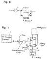
- Figure 1 shows a basic structure of the gas reclaiming equipment.
- the gas reclaiming equipment is used for reclaiming the gas from gas insulated equipment 1.
- the gas reclaiming equipment consists of a filter 2, a vacuum/compression pump 3, a gas liquefaction system 6, an SF 6 liquid tank 7, a refrigerator 11, and a cooling pipe 12.
- the gas-insulated equipment 1, the filter 2, the vacuum/compression pump 3, the gas liquefaction system 6, and the SF 6 liquid tank 7 are connected to each other through a pipe 13.
- a valve 14 for controlling the flow rate from the gas liquefaction system 6 or the SF 6 liquid tank 7 is provided.
- the filter 2 adsorbs decomposed gas of SF 6 , which occurs due to an arc.
- the filter also absorbs particulate foreign substances.
- an adsorbent is used for the purpose of removing moisture or decomposed gas.
- Zeolites with a pore size of approximately 5 ⁇ or 10 ⁇ (5 ⁇ 10 -10 m or 10 ⁇ 10 -10 m) are commonly used, since the decomposed gas molecules are larger than a molecule of H 2 O. Even, Zeolites with pore size of 9 ⁇ (9 ⁇ 10 -10 m) can be used. That is, the size depends on what kind of gas is being reclaimed.
- the SF 6 gas is sent into the gas liquefaction system 6 from the gas insulated equipment 1 through the vacuum/compression pump 3. Additionally, a refrigerant, like chlorofluorocarbon, is sent through the cooling pipe 12 from the refrigerator 11. The SF 6 gas is liquefied in the gas liquefaction system 6 and then the reclaimed SF 6 liquid is stored in liquid tank 7.
- the reactivity of HF is the highest and HF is chemisorbed. Its adsorption energy is about 100kcal/mol (419 J/mol). It is believed that the rest of the gasses are absorbed by physisorption. The adsorption energy in physisorption is approximately 1-4 kcal/about mol (4,19-16,75 J/about mol).
- physisorption is weaker in terms of adsorption. So, it is believed that gas molecules de-sorb from the adsorbent under the influence of molecular movement in a reduced pressure state. In addition, even if the molecule with weak adsorption is adsorbed by physisorption, when a molecule with strong adsorption arrives, the molecular with strong adsorption adsorbs such that the molecule with the strong adsorption replaces the molecule with weak adsorption.
- gases such as SOF 2 , SO 2 F 2 , CO 2 , SF 6 , CF 4 , N 2 , and O 2 de-sorb from the adsorbent. Therefore, gases such as SOF 2 , SO 2 F 2 , CO 2 , SF 6 , CF 4 , N 2 , and O 2 may exhaust from the gas insulated equipment 1, and may go into the reclaiming equipment. If so, the filter 2 catches the decomposed gas and any foreign substances, and prevents invasion of the decomposed gas and foreign substances into the gas liquefaction system 6.
- the quantity of exhaustd SF 6 gas needs to be reduced further.
- mixed gas having nitrogen gas as a main component and a little SF 6 gas
- nitrogen gas does not liquefy simultaneously. Nitrogen still exists as a gas. Therefore, it is possible to liquefy only SF 6 gas in a mixed gas and to separate SF 6 gas from nitrogen gas.
- the pressurization liquefaction of SF 6 gas is easy at room temperature, such as 20 degrees C.
- the concentrated SF 6 gas is liquefied in the gas liquefaction system 6, but the main composition gas, such as nitrogen gas, of the mixed gas continues to accumulate in the gas gradually liquefaction system 6. Therefore, before exceeding the design pressure of the gas liquefaction system 6, this main composition gas needs to be extracted from the gas liquefaction system 6.
- the main composition gas may contain some SF 6 gas, and thus the main composition gas cannot be emitted into the atmosphere. Therefore, in order to prevent the SF 6 gas from remaining in the main composition gas, the reclaiming ratio of SF 6 gas is preferably improved. Moreover, in considering reclaiming the mixed gas, the gas pressure in the gas-insulated equipment is high early in the reclaiming stage. Therefore, the gas automatically flows into the reclaiming equipment side by only opening a valve. As a result, adjusting the flow rate is easier.
- the reclaiming work under reduced pressure becomes necessary.
- the reclaiming work depends on the capability of the vacuum/pressurization pump.
- the processing quantity per unit time is reduced under reduced pressure. Therefore, it becomes difficult to secure a sufficient flow rate and the reclaiming efficiency is lowered.
- decomposed gas de-sorbs from the adsorbent in the gas insulated equipment beforehand. Therefore, the decomposed gas will be exhausted into the reclaiming equipment side.
- Decomposed gas If the decomposed gas enters the reclaiming equipment, the life of the reclaiming equipment is adversely affected. Decomposed gas causes, for example, chemical degradation of the pipes in the reclaiming equipment and degradation of the material of the adsorbent.
- an adsorbent having various Zeolites for example Zeolites with 5 ⁇ or 10 ⁇ (5 ⁇ 10 -10 m or 10 ⁇ 10 -10 m) pores, are usually enclosed.
- the adsorbent includes Zeolites with approximately 10 ⁇ (10 ⁇ 10 -10 m) pores which adsorbs SF 6 gas for reclaiming. Therefore, if there is a high quantity of the adsorbent, when reclaiming in a reduced pressure condition, the SF 6 gas will de-sorb from the gas insulated equipment side gradually for a long period of time. Therefore, there is a problem in that the reclaiming of SF 6 gas takes a long time.
- the adsorbent material has Zeolites with a size of 5 ⁇ (5 ⁇ 10 -10 m), it is difficult to adsorb a decomposed gas larger than 5 ⁇ (5 ⁇ 10 -10 m) in size, and the rate of absorption may decrease.
- the present invention has been made in view of the above-mentioned circumstances and is intended to solve the above-mentioned problems.
- the object of the present invention is to provide a gas reclaiming equipment having a simple and inexpensive structure, and capable of reclaiming SF 6 gas with high efficiency.
- the present invention provides a gas reclaiming equipment including the features of independent claims 1 or 4 and a method comprising the features of claim 13.
- Advantageous empodiments of the invention are defined in the subclaims.
- Fig. 2 is a diagram showing gas reclaiming equipment according to a first embodiment of the present invention.
- a gas separation equipment 5 is provided between a gas insulated equipment 1 and a gas liquefaction system 6.
- the gas separation equipment 5 separates nitrogen gas from mixed gas, and concentrates the SF 6 gas. Thereafter, concentrated SF 6 gas which contains small amount of nitrogen gas is sent into the gas liquefaction system 6.
- the gas separation equipment 5 includes pressure swing adsorption using an adsorbent with selective adsorption. Moreover, a buffer tank 4, which stores the mixed gas temporarily, is provided between the gas separation equipment 5 and the gas insulated equipment 1. The buffer tank 4 is operated on the condition that the inside of the buffer tank is pressurized at all times.
- the buffer tank 4 and the gas liquefaction system 6 are connected by a reflux-line 19.
- the reflux-line 19 refluxes the gas in a gas-phase from the gas liquefaction system 6 to the buffer tank 4.
- the gas-phase contains a small quantity of SF 6 gas which is equivalents to the vapor pressure of SF 6 .
- the gas separation equipment 5 is connected to a storage tank 8 for exhaust gas.
- the storage tank 8 accumulates the nitrogen gas separated through the gas separation equipment 5.
- the adsorbent 18 having approximately 10 ⁇ (10 ⁇ 10 -10 m) Zeolites for adsorbing SF 6 gas is enclosed in the storage tank 8 for the exhaust gas.
- a filter 2 having an adsorbent 2a of the chemisorption type to absorb decomposed gas is interposed between the gas insulated equipment and a pump 3.
- the adsorbent 2a has a metal hydrate, such as Ca(OH) 2 .
- a valve 14 controls the flow.
- a control unit 9 controls the entire gas reclaiming equipment.
- Zeolites shown in Fig. 3, used as the adsorbent, are enclosed in the gas separation equipment 5.
- Zeolites are a generic name for crystalline aluminosilicates of alkali.
- the general formula of Zeolites is shown by MeO ⁇ Al 2 O 3 ⁇ mSiO 2 ⁇ nH 2 O.
- Zeolites have uniform pores on their surface.
- a molecule smaller than the pore can pass along a narrow pipe of Zeolites, the molecule can be adsorbed inside, as illustrated in Fig. 10.
- the pores in the Zeolite act like small holes while the molecules of SF 6 and nitrogen gas act like small balls.
- the balls of the same size as the pores get stuck in the pores. This illustrates the outstanding selective adsorption, or molecular sieve effect.
- SF 6 gas and nitrogen gas differ from each other in molecular size.
- the size of the SF 6 molecule varies from DS5.49 - DL6.06, and the size of the nitrogen molecule has from DS3.1 - DL4.2.
- the unit of size is ⁇ or 10 -10 m.
- DS shows the shorter parameter of the molecule.
- DL shows the longer parameter of the molecule.
- Molecular size is described with DS and DL because of its non-spherical shape.
- SF 6 gas is not adsorbed. This is because SF 6 gas is larger than the pore in the Zeolite surface. Nitrogen gas is adsorbed alternatively, and separation of SF 6 gas is provided.
- Zeolites have a metal cation in the crystal structure.
- the metal cation attracts a polar group by static electricity, or a neutral molecule electrically by polarization.
- the metal cation is widely applicable based on the above mentioned reason.
- the gas separation equipment 5 separates the mixed gas with Zeolites by the selective adsorption mentioned above using the pressure swing adsorption method.
- the basic principle of the pressure swing adsorption method is that the adsorption quantity of the adsorbent is proportional to the gas pressure.
- Fig. 4 is a graph showing the relationship between the adsorption quantity and pressure.
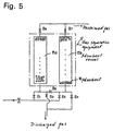
- Fig. 5 is a detailed diagram showing a main part of the gas separation equipment 5. That is, the gas separation equipment 5 has two adsorbent vessels 15a and 15b. An adsorbent 16 with 5 ⁇ Zeolites is contained in the two adsorbent vessels 15a and 15b.
- valves B1, B2, B3, B4, B5, B6 and B7 The fundamental run pattern of valves B1, B2, B3, B4, B5, B6 and B7 will now be explained.
- Valves B1 and B4 are open, and the other valves are closed.
- valve B4 is combined with the vacuum/compression pump 3 on the condition that valve B4 is open, and reduced pressure processing is carried out.
- the mixed gas in the gas insulated equipment flows to a down-stream side with the vacuum/compression pump 3, through the buffer tank 4.
- the mixed gas flows into the adsorbent vessel 15a in the gas separation equipment 5.
- the adsorbent vessel 15b is controlled by the vacuum/compression pump 3 under reduced pressure. It is in the early regeneration state and emits the adsorbed nitrogen gas. In the adsorbent vessel 15a, the adsorbent adsorbs only nitrogen gas by the molecular sieve effect. On the one hand, SF 6 gas flows along the upper part, along the flow route, raising its concentration. Finally, gas with high SF 6 gas concentration accumulates on the upper part of the adsorbent vessel 15a.
- valve B6 While valve B6 is closed, the flow route of mixed gas is changed into the adsorbent vessel 15b side by opening valve B3. Thus, SF 6 gas will be separated and concentrated in the adsorbent vessel 15b.
- reduced pressure processing in the adsorbent vessel 15a side is carried out, and the nitrogen gas de-sorbs. While the nitrogen gas is exhausted by opening valve B2, the adsorbent 16 will be in the initial state before the adsorbent starts adsorbing.
- mixed gas is separated into SF 6 gas and nitrogen gas.
- SF 6 concentrated gas is then sent into the gas liquefaction system 6.
- the initial performance deteriorates gradually due to the strong bonding of moisture and decomposed gas with the adsorbent 16.
- a designated purity control needs to be carried out.
- the gas flowed into the reclaiming equipment should be controlled.
- the liquefaction pressure will be set to about 4 MPa at room temperature. Therefore, the existing liquefaction equipment can be used and the risk of liquefaction under high-pressure is also decreased remarkably. Moreover, even though the liquefaction may be performed by using cooling, the increase in size of the equipment is avoidable.
- the liquefaction pressure can be reduced up to about 1.3 MPa.
- mixed gas can be accumulated in the buffer tank 4 temporarily. Therefore, the operation after the gas separation equipment 5 can be stopped, and sufficient flow rate and amount of mixture gas which put into the gas separation equipment 5 can be secured by gas accumulation into buffer tank 4. That is, the appropriate gas flow rate under the reduced pressure condition can be realized, and high reclaiming efficiency can be maintained.
- the decomposed gas contained in the mixed gas does not desorb. Furthermore, in the first embodiment, the adsorbent 2a of the chemisorption type in the filter 2 catches the decomposed gas with certainty. Therefore, the decomposed gas is mixed neither into the gas separation equipment 5 nor the gas liquefaction system 6.
- the performance degradation related to chemical factors and physical factors does not occur.
- the lifetime of the equipment can be prolonged.
- the adsorbent 18 in the storage tank 8 for exhaust gas adsorbs only SF 6 gas.
- the same effects can be obtained using the column containing the adsorbent 18 instead of the storage tank 8.
- Fig. 6 shows the change of SF 6 gas concentration of a mixed gas with 5% SF 6 gas at a pressure of 0.2MPa when using an adsorbent comprising 10 ⁇ (10 ⁇ 10 -10 m) Zeolites.
- Fig. 6 shows that the adsorbent also adsorbs a very small quantity of SF 6 gas with certainty.
- SF 6 gas adsorption with an adsorbent 18 having the 10 ⁇ (10 ⁇ 10 -10 m) Zeolites become saturated. Therefore, after the predetermined quantity processing of SF 6 gas, while SF 6 gas is reclaimed under the reduced pressure, the adsorbent 18 needs to be restored into its initial condition.
- the vacuum/compression pump 3 sends the mixed gas having nitrogen gas, which is the main ingredient, and SF 6 gas into the buffer tank 4, through the piping 13.
- the adsorption power of the adsorbent is in inverse proportion to temperature. That is, if temperature is lowered, SF 6 gas adsorbed to the Zeolites increases. On the one hand, SF 6 gas remaining in the gas phase decreases.
- the temperature is raised, the adsorption power will decline, and if the temperature is lowered, the adsorption power increases. That is, when the reproducing of adsorbent work is required in a short time, it is better that the temperature is at 80-100 degrees C.
- SF 6 gas can be adsorbed by supplying exhaust gas into an adsorbent vessel filled with an adsorbent 18 of 10 ⁇ (10 ⁇ 10 -10 m) Zeolites.
- adsorbent 18 10 ⁇ (10 ⁇ 10 -10 m) Zeolites.
- the reduced pressure processing is carried out at a gas exit side
- SF 6 gas will disperse to the adsorbent in a non-adsorbed portion. Therefore, it is better to perform the reduced pressure processing and to reproduce the adsorbent from the gas entrance side of the column (not shown) provided in the storage tank 8 for exhaust gas. Therefore, it is not necessary to supply a trap at the storage tank 8. That is, the same effect as the mentioned effect can be attained by flowing the exhaust gas to the adsorbent vessel, filled with the adsorbent 18 having 10 ⁇ (10 ⁇ 10 -10 m) Zeolites.
- the gas separation equipment 5 separates mixed gas into SF 6 gas and nitrogen gas. In this separation operation, preventing SF 6 gas mixing into nitrogen gas as much as possible is desirable. For this reason, when sending SF 6 gas reclaimed in the gas separation equipment 5 to the pump 3, SF 6 gas is also reclaimed by supplying the nitrogen gas together.
- nitrogen gas can be returned to the buffer tank 4 from the gas liquefaction system 6 through the reflux-line 19.
- the reclaiming efficiency of SF 6 gas improves sharply by passing this gas again through the gas separation equipment 5 and the gas liquefaction system 6, even though SF 6 gas remains mixed in the nitrogen gas. Therefore, in the reclaiming SF 6 gas, the amount of exhaust of SF 6 gas to the atmosphere can be ignored.
- a second embodiment is shown in Fig. 7 and Fig. 8.
- the second embodiment encloses an adsorbent 16 with 5 ⁇ and 10 ⁇ (5 ⁇ 10 -10 m or 10 ⁇ 10 -10 m) Zeolites in the buffer tank 4.
- Fig. 7 two buffer tanks 4a and 4b are provided. Furthermore, the adsorbent 16 is enclosed only within the buffer tank 4b. In this embodiment, the pressure of the mixed gas is reduced by controlling the valve 14, and mixed gas is reclaimed.
- the buffer tanks 4a and 4b, having the adsorbent 16, serve so that the mixed gas may be stored.
- the adsorbent 16 enclosed in the buffer tank 4b can reliably catch the decomposed gas which pass through the filter 2.
- the decomposed gas does not mix in the gas separation equipment 5 or the gas liquefaction system 6. Therefore, it is possible to prevent the chemical degradation and physical degradation and to prolong the lifetime of the equipment.
- the mixed gas can be stored in the buffer tanks 4a and 4b. Further, the mixed gas can only be passed under a designated pressurization state through the buffer tanks 4a and 4b to an atmospheric pressure.
- the mixed gas can be reclaimed quickly, and shortening of reclaiming work hours can be attained.
- an adsorbent 16 with 5 ⁇ and 10 ⁇ (5 ⁇ 10 -10 m or 10 ⁇ 10 -10 m) Zeolites is used, the quantity of the adsorption of SF 6 gas can be suppressed. Furthermore, it is possible to adsorb a molecule larger than 5 ⁇ (5 ⁇ 10 -10 m) quickly from the decomposed gas.
- a film for the gas separation equipment can be used. That is, the thing adapting the difference of the dissolution to a molecular size, a film material for example, can be considered.
- a film material made from a macromolecule can be used as an example.
- the gas reclaiming equipment can have plural gas separation units.
- This embodiment is illustrated in Fig. 9.
- the mixed gas is led to a 1st gas separation unit 21, and the 1st step gas separation unit 21 reclaims concentrated SF 6 gas.
- gas exhausted from the gas reclaiming equipment is led to a 2nd gas separation unit 23.
- the 2nd step of the gas separation unit 23 again concentrates SF 6 gas contained in a very small quantity.
- SF 6 gas with high purity and the reduction of the liquefaction pressure of SF 6 gas can be attained by performing plural gas separation processes.
- another embodiment relates to the gas insulated equipment side for making gas reclaiming easy.
- an adsorbent with 5 ⁇ and 10 ⁇ (5 ⁇ 10 -10 m or 10 ⁇ 10 -10 m) Zeolites is enclosed as a decomposed gas removal material and a desiccant in the gas insulated equipment 1.
- the embodiment is characterized by enclosing an adsorbent mixture with 5 ⁇ and 10 ⁇ (5 ⁇ 10 -10 m or 10 ⁇ 10 -10 m) Zeolites.
- the former becomes more than 80wt% and the latter becomes less than 20wt%.
- the quantity of SO 2 F 2 generated is small compared with SOF 2 generated, and it is known that it is ordinarily 1/10 or less.
- the adsorbent has two types, approximately 5 ⁇ (5 ⁇ 10 -10 m) size and 10 ⁇ (10 ⁇ 10 -10 m) size of pores in the gas-insulated equipment 1, according to the above-mentioned ratio.
- the quantity of SF 6 gas adsorption in the gas insulated equipment 1 can be minimized, while maintaining the adsorption performance of the decomposed gas. That is, SF 6 gas does not escape from the gas-insulated equipment 1 for a long period of time, when reduced pressure reclaiming is performed. Consequently, reclaiming working hours can be shortened and reclaiming efficiency improved.
- the reclaiming performance of SF 6 gas can be improved by setting the reflux-line and returning the gas in the gas phase in the gas liquefaction system to the mixed gas introduction section.
- SF 6 gas and other insulated gases are efficiently separable with a unique adsorption action of the adsorbent.
- Shortening of reclaiming working hours can be attained by this separation, raising SF 6 gas concentration and raising the reclaiming efficiency under reduced pressure. Furthermore, according to the present invention, longevity of the life of the equipment can be enabled by removing decomposed gas exhausted from the gas insulated equipment. Furthermore, the optimization of the combination and ratio in the adsorbent in the gas insulated equipment can be attained, and outstanding reclaiming efficiency can be demonstrated.
Landscapes
- Chemical & Material Sciences (AREA)
- Engineering & Computer Science (AREA)
- Analytical Chemistry (AREA)
- General Chemical & Material Sciences (AREA)
- Oil, Petroleum & Natural Gas (AREA)
- Chemical Kinetics & Catalysis (AREA)
- Health & Medical Sciences (AREA)
- Biomedical Technology (AREA)
- Environmental & Geological Engineering (AREA)
- Gas-Insulated Switchgears (AREA)
- Separation Of Gases By Adsorption (AREA)
- Driving Mechanisms And Operating Circuits Of Arc-Extinguishing High-Tension Switches (AREA)
Applications Claiming Priority (2)
| Application Number | Priority Date | Filing Date | Title |
|---|---|---|---|
| JP28204599A JP4357046B2 (ja) | 1999-10-01 | 1999-10-01 | ガス回収装置 |
| JP28204599 | 1999-10-01 |
Publications (3)
| Publication Number | Publication Date |
|---|---|
| EP1091182A2 true EP1091182A2 (de) | 2001-04-11 |
| EP1091182A3 EP1091182A3 (de) | 2002-01-16 |
| EP1091182B1 EP1091182B1 (de) | 2004-11-17 |
Family
ID=17647459
Family Applications (1)
| Application Number | Title | Priority Date | Filing Date |
|---|---|---|---|
| EP00121476A Expired - Lifetime EP1091182B1 (de) | 1999-10-01 | 2000-09-29 | Vorrichtung zur Gasrückgewinnung |
Country Status (4)
| Country | Link |
|---|---|
| US (1) | US6966934B1 (de) |
| EP (1) | EP1091182B1 (de) |
| JP (1) | JP4357046B2 (de) |
| DE (1) | DE60015900T2 (de) |
Cited By (10)
| Publication number | Priority date | Publication date | Assignee | Title |
|---|---|---|---|---|
| WO2014173776A1 (en) * | 2013-04-22 | 2014-10-30 | Abb Technology Ag | Process for providing a contamination-reducing component to an electrical apparatus |
| WO2014187940A1 (en) * | 2013-05-23 | 2014-11-27 | Abb Technology Ag | Electrical apparatus comprising a contamination-reducing component |
| WO2015071303A1 (en) * | 2013-11-12 | 2015-05-21 | Abb Technology Ag | Water and contamination absorber for c02 insulated electrical apparatus for the generation, transmission, distribution and/or usage of electrical energy |
| EP2904617B1 (de) | 2012-10-05 | 2016-11-30 | ABB Schweiz AG | Vorrichtung mit dielektrischem isoliergas mit einer organofluorverbindung |
| WO2016193272A1 (de) * | 2015-06-02 | 2016-12-08 | Firma Dilo Armaturen Und Anlagen Gmbh | Servicegerät für den einsatz bei der wartung von elektrischen schaltanlagen isoliert mit ein mehrkomponentiges isoliergas |
| WO2017012775A1 (de) * | 2015-07-20 | 2017-01-26 | Siemens Aktiengesellschaft | Hoch- und mittelspannungsanordnung mit einem isolierraum und einem absorber mit selektiver membran |
| EP3069421B1 (de) | 2013-11-12 | 2017-09-20 | ABB Schweiz AG | Wasser- und kontaminationsabsorber für eine co2-isolierte elektrische vorrichtung zur erzeugung, übertragung, verteilung und/oder verwendung elektrischer energie |
| EP3146531B1 (de) | 2014-05-20 | 2018-03-21 | ABB Schweiz AG | Elektrische vorrichtung zur erzeugung, übertragung, verteilung und/oder verwendung von elektrischer energie und verfahren zur rückgewinnung eines stoffes aus einem isolationsmedium einer solchen vorrichtung |
| WO2019047349A1 (zh) * | 2017-09-08 | 2019-03-14 | 河南平高电气股份有限公司 | 气体回收充气装置和六氟化硫气体回收充气装置 |
| EP3834917A1 (de) * | 2019-12-13 | 2021-06-16 | WIKA Alexander Wiegand SE & Co. KG | Serviceanlage für gasräume |
Families Citing this family (14)
| Publication number | Priority date | Publication date | Assignee | Title |
|---|---|---|---|---|
| US9064372B2 (en) | 2002-02-15 | 2015-06-23 | Wms Gaming Inc. | Wagering game with simulated mechanical reels having an overlying image display |
| JP4596531B2 (ja) * | 2005-03-11 | 2010-12-08 | 財団法人電力中央研究所 | ガス絶縁電力機器及びその異常検出方法 |
| JP5020059B2 (ja) * | 2007-12-28 | 2012-09-05 | 三菱電機株式会社 | ガス絶縁開閉装置 |
| KR101155996B1 (ko) | 2010-09-30 | 2012-06-18 | 한국에너지기술연구원 | 절연가스 회수장치 및 이의 운용방법 |
| DE102015206744A1 (de) * | 2015-04-15 | 2016-11-03 | Rwe Deutschland Ag | Verfahren zum Trocknen eines Gasraums sowie Anordnung umfassend einen schutzgasbefüllten Gasraum |
| DE102015213597A1 (de) * | 2015-07-20 | 2017-01-26 | Siemens Aktiengesellschaft | Hoch- oder Mittelspannungsanordnung mit Isolierraum und Absorptionsmittel |
| EP3174071B1 (de) * | 2015-11-30 | 2018-11-14 | General Electric Technology GmbH | Verfahren und anlage zum befüllen einer gasisolierten elektrischen geräteanordnung, die eine mischung aus (cf3)2cfcn und co2 umfasst |
| DE102016215598A1 (de) * | 2016-08-19 | 2018-02-22 | Siemens Aktiengesellschaft | Elektroenergieübertragungseinrichtung sowie Lebenszyklusmanagement |
| CN106352658B (zh) * | 2016-10-27 | 2022-06-07 | 刘克军 | 一种环己酮装置氧化尾气治理装置及其应用 |
| CN107726043B (zh) * | 2017-09-08 | 2020-04-07 | 国家电网公司 | 一种110kV六氟化硫气体绝缘电流互感器的混合气体改造方法 |
| CN108101006B (zh) * | 2017-12-20 | 2020-01-24 | 国网河北省电力有限公司电力科学研究院 | 一种sf6和n2混合气体快速回收处理装置和方法 |
| CN108261885A (zh) * | 2017-12-29 | 2018-07-10 | 浙江环耀环境建设有限公司 | 一种有机废气处理系统及溶剂回收工艺 |
| CN110833730A (zh) * | 2019-11-15 | 2020-02-25 | 昆山开信精工机械股份有限公司 | 一种可液化气体的氮气混合材料分离装置及其分离方法 |
| CN117213169A (zh) * | 2023-08-25 | 2023-12-12 | 国网青海省电力公司超高压公司 | 一种sf6/cf4混合气体快速分离回收装置及方法 |
Family Cites Families (33)
| Publication number | Priority date | Publication date | Assignee | Title |
|---|---|---|---|---|
| US3210952A (en) * | 1961-12-11 | 1965-10-12 | Westinghouse Electric Corp | Reclamation device for gas-type circuit interrupters |
| DE1212945B (de) * | 1964-07-07 | 1966-03-24 | Kali Chemie Ag | Verfahren zur Entfernung von Sulfurylfluorid aus Schwefelhexafluorid enthaltenden Gasgemischen |
| US3675392A (en) * | 1970-01-30 | 1972-07-11 | Ite Imperial Corp | Adsorption-desorption method for purifying sf{11 |
| DE2336331A1 (de) * | 1973-07-12 | 1975-01-30 | Rudolf Dittmar | Verfahren zum reinigen von schwefelhexafluorid |
| JPS545393B2 (de) * | 1973-08-08 | 1979-03-16 | ||
| US3992159A (en) * | 1975-06-23 | 1976-11-16 | Bell Telephone Laboratories, Incorporated | Process for purification by cryogenic sublimation |
| AU520049B2 (en) * | 1976-08-16 | 1982-01-14 | University Of Sydney, The | Cryogenic pumping system |
| AU4587479A (en) * | 1978-04-07 | 1979-10-11 | Commonwealth Industrial Gases Limited, The | Pressure-swing preferential adsorption of condensible vapour from gas stream |
| JPH0127240Y2 (de) * | 1980-03-03 | 1989-08-15 | ||
| JPS59179414U (ja) * | 1983-05-17 | 1984-11-30 | 株式会社東芝 | ガス絶縁機器におけるsf6液化回収装置 |
| JPS6018775A (ja) * | 1983-07-11 | 1985-01-30 | Mitsubishi Electric Corp | ガス絶縁電気機器の内部異常検出装置 |
| JPS61167309A (ja) * | 1985-01-18 | 1986-07-29 | 株式会社東芝 | ガス置換装置 |
| JPS6326497A (ja) * | 1986-07-17 | 1988-02-04 | Kachi Tekkosho:Kk | ガス置換回収装置 |
| JPH0755807B2 (ja) * | 1987-11-04 | 1995-06-14 | 三井東圧化学株式会社 | 三弗化窒素の製造方法 |
| JP3027606B2 (ja) * | 1989-06-15 | 2000-04-04 | デユポン・カナダ・インコーポレーテツド | パーフルオロジオキソール膜 |
| JPH04293512A (ja) * | 1991-03-25 | 1992-10-19 | Kobe Steel Ltd | ガス精製装置 |
| US5240471A (en) * | 1991-07-02 | 1993-08-31 | L'air Liquide | Multistage cascade-sweep process for membrane gas separation |
| US5252219A (en) * | 1992-12-18 | 1993-10-12 | Permea, Inc. | Compressed permeate sweep membrane separation process |
| US5378263A (en) * | 1992-12-21 | 1995-01-03 | Praxair Technology, Inc. | High purity membrane nitrogen |
| US5482539A (en) * | 1993-09-22 | 1996-01-09 | Enerfex, Inc. | Multiple stage semi-permeable membrane process and apparatus for gas separation |
| US5417742A (en) * | 1993-12-03 | 1995-05-23 | The Boc Group, Inc. | Removal of perfluorocarbons from gas streams |
| US5455016A (en) * | 1994-08-31 | 1995-10-03 | Air Products And Chemicals, Inc. | Membrane-assisted process to produce ammonia |
| US5502969A (en) * | 1995-02-16 | 1996-04-02 | Praxair Technology, Inc. | Cryogenic rectification system for fluorine compound recovery |
| FR2730790B1 (fr) * | 1995-02-17 | 1997-05-23 | Air Liquide | Procede d'introduction d'un gaz de remplissage dans une enceinte et installation de mise en oeuvre |
| JPH08309146A (ja) * | 1995-05-22 | 1996-11-26 | Boc Group Inc:The | ガス流れからペルフルオロカーボン類を分離除去する方法 |
| US5785741A (en) * | 1995-07-17 | 1998-07-28 | L'air Liquide, Societe Anonyme Pour L'etude Et L'exploitation Des Procedes Georges, Claude | Process and system for separation and recovery of perfluorocompound gases |
| US5858065A (en) * | 1995-07-17 | 1999-01-12 | American Air Liquide | Process and system for separation and recovery of perfluorocompound gases |
| JP3237514B2 (ja) * | 1996-04-23 | 2001-12-10 | 三菱電機株式会社 | 六弗化硫黄ガスの回収再生装置、ならびに、移動式回収再生装置 |
| US5730779A (en) * | 1996-10-31 | 1998-03-24 | Air Products And Chemicals, Inc. | Fluorochemical recovery and recycle using membranes |
| US5720797A (en) * | 1996-12-18 | 1998-02-24 | Alliedsignal Inc. | Process for recovering sulfur hexafluoride |
| JP3356965B2 (ja) * | 1997-06-20 | 2002-12-16 | 株式会社日立製作所 | Sf6ガス回収・精製処理装置及び方法 |
| US6164088A (en) * | 1998-07-27 | 2000-12-26 | Mitsubishi Denki Kaishushiki Kaisha | Method for recovering condensable gas from mixed gas and condensable gas recovering apparatus |
| DE19910678A1 (de) * | 1998-08-20 | 2000-09-14 | Solvay Fluor & Derivate | Verfahren zur Reinigung von SF¶6¶-kontaminierten Gasen |
-
1999
- 1999-10-01 JP JP28204599A patent/JP4357046B2/ja not_active Expired - Fee Related
-
2000
- 2000-09-29 US US09/672,775 patent/US6966934B1/en not_active Expired - Fee Related
- 2000-09-29 EP EP00121476A patent/EP1091182B1/de not_active Expired - Lifetime
- 2000-09-29 DE DE60015900T patent/DE60015900T2/de not_active Expired - Lifetime
Cited By (15)
| Publication number | Priority date | Publication date | Assignee | Title |
|---|---|---|---|---|
| EP2904617B1 (de) | 2012-10-05 | 2016-11-30 | ABB Schweiz AG | Vorrichtung mit dielektrischem isoliergas mit einer organofluorverbindung |
| WO2014173776A1 (en) * | 2013-04-22 | 2014-10-30 | Abb Technology Ag | Process for providing a contamination-reducing component to an electrical apparatus |
| WO2014187940A1 (en) * | 2013-05-23 | 2014-11-27 | Abb Technology Ag | Electrical apparatus comprising a contamination-reducing component |
| US10522981B2 (en) | 2013-11-12 | 2019-12-31 | Abb Schweiz Ag | Water and contamination absorber for C02 insulated electrical apparatus for the generation, transmission, distribution and/or usage of electrical energy |
| WO2015071303A1 (en) * | 2013-11-12 | 2015-05-21 | Abb Technology Ag | Water and contamination absorber for c02 insulated electrical apparatus for the generation, transmission, distribution and/or usage of electrical energy |
| CN105874665A (zh) * | 2013-11-12 | 2016-08-17 | Abb 技术有限公司 | 用于产生、传输、分配和/或使用电能的co2绝缘电装置的水和污染物吸收剂 |
| EP3069421B1 (de) | 2013-11-12 | 2017-09-20 | ABB Schweiz AG | Wasser- und kontaminationsabsorber für eine co2-isolierte elektrische vorrichtung zur erzeugung, übertragung, verteilung und/oder verwendung elektrischer energie |
| CN105874665B (zh) * | 2013-11-12 | 2019-06-21 | Abb瑞士股份有限公司 | 用于产生、传输、分配和/或使用电能的co2绝缘电装置的水和污染物吸收剂 |
| EP3146531B1 (de) | 2014-05-20 | 2018-03-21 | ABB Schweiz AG | Elektrische vorrichtung zur erzeugung, übertragung, verteilung und/oder verwendung von elektrischer energie und verfahren zur rückgewinnung eines stoffes aus einem isolationsmedium einer solchen vorrichtung |
| WO2016193272A1 (de) * | 2015-06-02 | 2016-12-08 | Firma Dilo Armaturen Und Anlagen Gmbh | Servicegerät für den einsatz bei der wartung von elektrischen schaltanlagen isoliert mit ein mehrkomponentiges isoliergas |
| US10914424B2 (en) | 2015-06-02 | 2021-02-09 | Dilo Armaturen Und Anlagen Gmbh | Service device and method for using a multi-component insulating gas during maintenance of electrical switchgear systems |
| WO2017012775A1 (de) * | 2015-07-20 | 2017-01-26 | Siemens Aktiengesellschaft | Hoch- und mittelspannungsanordnung mit einem isolierraum und einem absorber mit selektiver membran |
| WO2019047349A1 (zh) * | 2017-09-08 | 2019-03-14 | 河南平高电气股份有限公司 | 气体回收充气装置和六氟化硫气体回收充气装置 |
| EP3834917A1 (de) * | 2019-12-13 | 2021-06-16 | WIKA Alexander Wiegand SE & Co. KG | Serviceanlage für gasräume |
| US12157088B2 (en) | 2019-12-13 | 2024-12-03 | Wika Alexander Wiegand Se & Co. Kg | Service system for gas compartments |
Also Published As
| Publication number | Publication date |
|---|---|
| DE60015900T2 (de) | 2005-11-03 |
| EP1091182A3 (de) | 2002-01-16 |
| JP2001110284A (ja) | 2001-04-20 |
| DE60015900D1 (de) | 2004-12-23 |
| US6966934B1 (en) | 2005-11-22 |
| EP1091182B1 (de) | 2004-11-17 |
| JP4357046B2 (ja) | 2009-11-04 |
Similar Documents
| Publication | Publication Date | Title |
|---|---|---|
| EP1091182B1 (de) | Vorrichtung zur Gasrückgewinnung | |
| CN103561846B (zh) | 从废气流吸附回收高价值成分的方法和系统 | |
| US6004377A (en) | System for collecting and refining SF6 gas and method therefor | |
| JP3891834B2 (ja) | ガス供給方法及び装置 | |
| US6613126B2 (en) | Method for storing natural gas by adsorption and adsorbing agent for use therein | |
| US7824472B2 (en) | Method and apparatus for pressure swing adsorption | |
| EP1759760A2 (de) | Adsorptionsmittel für die Adsorption und Lagerung von Erdgas sowie seine Verwendung | |
| CA2991985C (en) | Pretreatment equipment for hydrocarbon gas to be liquefied and shipping base equipment | |
| KR20190052018A (ko) | 수소 또는 헬륨의 정제방법 및 수소 또는 헬륨의 정제장치 | |
| JP2003103134A (ja) | Sf6ガス捕集装置およびその方法 | |
| KR100790696B1 (ko) | 가스상태 탄화수소의 처리 및 회수 장치 및 그 방법 | |
| JP2000262806A (ja) | 吸着剤の再生方法 | |
| JP4405039B2 (ja) | ガス回収装置及びガス回収方法 | |
| JP2001143580A (ja) | ガス分離回収装置 | |
| JP2000274938A (ja) | ガス回収装置 | |
| US7392657B2 (en) | Methods of dissolving ozone in a cryogen | |
| JP2000135412A (ja) | ガス回収装置及びガス回収方法 | |
| JP2001283692A (ja) | Sf6ガス分離回収装置 | |
| JP2587334B2 (ja) | Ch4を含まないcoガスの分離方法 | |
| CN116272241B (zh) | 一种稀有气体低温纯化气路及其控制方法 | |
| US20250288942A1 (en) | Gas recovery device and recovery method | |
| JP2001056098A (ja) | 天然ガスの吸着貯蔵方法およびこれに使用する吸着材 | |
| WO2010113258A1 (ja) | ガス状炭化水素の回収装置及び方法 | |
| JP2003299931A (ja) | ガス分離方法及びガス分離装置 | |
| JP2018177567A (ja) | 水素ガス精製装置、及び水素ガス精製装置の運転方法 |
Legal Events
| Date | Code | Title | Description |
|---|---|---|---|
| PUAI | Public reference made under article 153(3) epc to a published international application that has entered the european phase |
Free format text: ORIGINAL CODE: 0009012 |
|
| 17P | Request for examination filed |
Effective date: 20000929 |
|
| AK | Designated contracting states |
Kind code of ref document: A2 Designated state(s): AT BE CH CY DE DK ES FI FR GB GR IE IT LI LU MC NL PT SE Kind code of ref document: A2 Designated state(s): CH DE LI |
|
| AX | Request for extension of the european patent |
Free format text: AL;LT;LV;MK;RO;SI |
|
| PUAL | Search report despatched |
Free format text: ORIGINAL CODE: 0009013 |
|
| RIC1 | Information provided on ipc code assigned before grant |
Free format text: 7F 25J 3/06 A, 7F 25J 3/08 B, 7B 01D 53/04 B |
|
| AK | Designated contracting states |
Kind code of ref document: A3 Designated state(s): AT BE CH CY DE DK ES FI FR GB GR IE IT LI LU MC NL PT SE |
|
| AX | Request for extension of the european patent |
Free format text: AL;LT;LV;MK;RO;SI |
|
| AKX | Designation fees paid |
Free format text: CH DE LI |
|
| 17Q | First examination report despatched |
Effective date: 20030821 |
|
| GRAP | Despatch of communication of intention to grant a patent |
Free format text: ORIGINAL CODE: EPIDOSNIGR1 |
|
| GRAS | Grant fee paid |
Free format text: ORIGINAL CODE: EPIDOSNIGR3 |
|
| GRAA | (expected) grant |
Free format text: ORIGINAL CODE: 0009210 |
|
| AK | Designated contracting states |
Kind code of ref document: B1 Designated state(s): CH DE LI |
|
| REG | Reference to a national code |
Ref country code: CH Ref legal event code: EP |
|
| REG | Reference to a national code |
Ref country code: IE Ref legal event code: FG4D |
|
| REF | Corresponds to: |
Ref document number: 60015900 Country of ref document: DE Date of ref document: 20041223 Kind code of ref document: P |
|
| REG | Reference to a national code |
Ref country code: CH Ref legal event code: NV Representative=s name: E. BLUM & CO. PATENTANWAELTE |
|
| PLBE | No opposition filed within time limit |
Free format text: ORIGINAL CODE: 0009261 |
|
| STAA | Information on the status of an ep patent application or granted ep patent |
Free format text: STATUS: NO OPPOSITION FILED WITHIN TIME LIMIT |
|
| 26N | No opposition filed |
Effective date: 20050818 |
|
| REG | Reference to a national code |
Ref country code: CH Ref legal event code: PFA Owner name: KABUSHIKI KAISHA TOSHIBA Free format text: KABUSHIKI KAISHA TOSHIBA#72 HORIKAWA-CHO, SAIWAI-KU#KAWASAKI-SHI, KANAGAWA-KEN (JP) -TRANSFER TO- KABUSHIKI KAISHA TOSHIBA#72 HORIKAWA-CHO, SAIWAI-KU#KAWASAKI-SHI, KANAGAWA-KEN (JP) |
|
| PGFP | Annual fee paid to national office [announced via postgrant information from national office to epo] |
Ref country code: CH Payment date: 20140915 Year of fee payment: 15 Ref country code: DE Payment date: 20140923 Year of fee payment: 15 |
|
| REG | Reference to a national code |
Ref country code: DE Ref legal event code: R119 Ref document number: 60015900 Country of ref document: DE |
|
| REG | Reference to a national code |
Ref country code: CH Ref legal event code: PL |
|
| PG25 | Lapsed in a contracting state [announced via postgrant information from national office to epo] |
Ref country code: CH Free format text: LAPSE BECAUSE OF NON-PAYMENT OF DUE FEES Effective date: 20150930 Ref country code: DE Free format text: LAPSE BECAUSE OF NON-PAYMENT OF DUE FEES Effective date: 20160401 Ref country code: LI Free format text: LAPSE BECAUSE OF NON-PAYMENT OF DUE FEES Effective date: 20150930 |