EP1091470A2 - Automatische Abschaltvorrichtung - Google Patents
Automatische Abschaltvorrichtung Download PDFInfo
- Publication number
- EP1091470A2 EP1091470A2 EP00850131A EP00850131A EP1091470A2 EP 1091470 A2 EP1091470 A2 EP 1091470A2 EP 00850131 A EP00850131 A EP 00850131A EP 00850131 A EP00850131 A EP 00850131A EP 1091470 A2 EP1091470 A2 EP 1091470A2
- Authority
- EP
- European Patent Office
- Prior art keywords
- shaft
- gear train
- rotatable
- linear actuator
- shaft member
- Prior art date
- Legal status (The legal status is an assumption and is not a legal conclusion. Google has not performed a legal analysis and makes no representation as to the accuracy of the status listed.)
- Granted
Links
Images


Classifications
-
- F—MECHANICAL ENGINEERING; LIGHTING; HEATING; WEAPONS; BLASTING
- F16—ENGINEERING ELEMENTS AND UNITS; GENERAL MEASURES FOR PRODUCING AND MAINTAINING EFFECTIVE FUNCTIONING OF MACHINES OR INSTALLATIONS; THERMAL INSULATION IN GENERAL
- F16H—GEARING
- F16H25/00—Gearings comprising primarily only cams, cam-followers and screw-and-nut mechanisms
- F16H25/18—Gearings comprising primarily only cams, cam-followers and screw-and-nut mechanisms for conveying or interconverting oscillating or reciprocating motions
- F16H25/20—Screw mechanisms
- F16H25/2015—Means specially adapted for stopping actuators in the end position; Position sensing means
-
- F—MECHANICAL ENGINEERING; LIGHTING; HEATING; WEAPONS; BLASTING
- F16—ENGINEERING ELEMENTS AND UNITS; GENERAL MEASURES FOR PRODUCING AND MAINTAINING EFFECTIVE FUNCTIONING OF MACHINES OR INSTALLATIONS; THERMAL INSULATION IN GENERAL
- F16H—GEARING
- F16H25/00—Gearings comprising primarily only cams, cam-followers and screw-and-nut mechanisms
- F16H25/18—Gearings comprising primarily only cams, cam-followers and screw-and-nut mechanisms for conveying or interconverting oscillating or reciprocating motions
- F16H25/20—Screw mechanisms
- F16H2025/2062—Arrangements for driving the actuator
- F16H2025/2081—Parallel arrangement of drive motor to screw axis
-
- F—MECHANICAL ENGINEERING; LIGHTING; HEATING; WEAPONS; BLASTING
- F16—ENGINEERING ELEMENTS AND UNITS; GENERAL MEASURES FOR PRODUCING AND MAINTAINING EFFECTIVE FUNCTIONING OF MACHINES OR INSTALLATIONS; THERMAL INSULATION IN GENERAL
- F16H—GEARING
- F16H25/00—Gearings comprising primarily only cams, cam-followers and screw-and-nut mechanisms
- F16H25/18—Gearings comprising primarily only cams, cam-followers and screw-and-nut mechanisms for conveying or interconverting oscillating or reciprocating motions
- F16H25/20—Screw mechanisms
- F16H25/2021—Screw mechanisms with means for avoiding overloading
-
- F—MECHANICAL ENGINEERING; LIGHTING; HEATING; WEAPONS; BLASTING
- F16—ENGINEERING ELEMENTS AND UNITS; GENERAL MEASURES FOR PRODUCING AND MAINTAINING EFFECTIVE FUNCTIONING OF MACHINES OR INSTALLATIONS; THERMAL INSULATION IN GENERAL
- F16H—GEARING
- F16H25/00—Gearings comprising primarily only cams, cam-followers and screw-and-nut mechanisms
- F16H25/18—Gearings comprising primarily only cams, cam-followers and screw-and-nut mechanisms for conveying or interconverting oscillating or reciprocating motions
- F16H25/20—Screw mechanisms
- F16H25/22—Screw mechanisms with balls, rollers, or similar members between the co-operating parts; Elements essential to the use of such members
- F16H25/2204—Screw mechanisms with balls, rollers, or similar members between the co-operating parts; Elements essential to the use of such members with balls
-
- Y—GENERAL TAGGING OF NEW TECHNOLOGICAL DEVELOPMENTS; GENERAL TAGGING OF CROSS-SECTIONAL TECHNOLOGIES SPANNING OVER SEVERAL SECTIONS OF THE IPC; TECHNICAL SUBJECTS COVERED BY FORMER USPC CROSS-REFERENCE ART COLLECTIONS [XRACs] AND DIGESTS
- Y10—TECHNICAL SUBJECTS COVERED BY FORMER USPC
- Y10T—TECHNICAL SUBJECTS COVERED BY FORMER US CLASSIFICATION
- Y10T74/00—Machine element or mechanism
- Y10T74/18—Mechanical movements
- Y10T74/18568—Reciprocating or oscillating to or from alternating rotary
- Y10T74/18576—Reciprocating or oscillating to or from alternating rotary including screw and nut
- Y10T74/18688—Limit stop
-
- Y—GENERAL TAGGING OF NEW TECHNOLOGICAL DEVELOPMENTS; GENERAL TAGGING OF CROSS-SECTIONAL TECHNOLOGIES SPANNING OVER SEVERAL SECTIONS OF THE IPC; TECHNICAL SUBJECTS COVERED BY FORMER USPC CROSS-REFERENCE ART COLLECTIONS [XRACs] AND DIGESTS
- Y10—TECHNICAL SUBJECTS COVERED BY FORMER USPC
- Y10T—TECHNICAL SUBJECTS COVERED BY FORMER US CLASSIFICATION
- Y10T74/00—Machine element or mechanism
- Y10T74/18—Mechanical movements
- Y10T74/18568—Reciprocating or oscillating to or from alternating rotary
- Y10T74/18576—Reciprocating or oscillating to or from alternating rotary including screw and nut
- Y10T74/18696—Reciprocating or oscillating to or from alternating rotary including screw and nut including means to selectively transmit power [e.g., clutch, etc.]
Definitions
- This invention relates generally to linear actuators, and more particularly to a linear actuator which automatically disconnects the output shaft assembly from the gear train at a predetermined position.
- Linear actuators are used to provide linear motion in a variety of applications.
- the basic design of a linear actuator consists of an electrical motor, gear train and the output shaft assembly (together with the ball or threaded screw as the main component generating linear movement of the output shaft).
- the output shaft assembly typically, at the ends of the output shaft linear travel there are limit switches which disconnect the electrical power in the motor and mechanical stops for preventing potential damage from the output shaft overtravel in case of a limit switch failure.
- the output shaft assembly should be disconnected from the actuator gear train to allow free movement of the output shaft. This design capability is necessary in case of electric power failure, for maintenance and more important, in case of emergency and safety concerns, as for instance, a foreign object which becomes trapped during retraction.
- the apparatus according to the present invention disclosed herein automatically disconnects the output shaft assembly from the gear train at a full retracted position, when manual operation is mostly required; or if necessary, at full extended position.
- This design allows manual operation of the actuator without the use of an external cable and without electrical power.
- the apparatus according to the present invention provides for the incorporation of a device limiting the tension load exerted by the actuator along its entire stroke or at a specified location. As a result, the actuator will stop an operation when the tension load exceeds the preset threshold limit.
- a linear actuator for generating linear movement of a shaft member comprising an electrically powered gear train coupled to a shaft assembly disposed in a housing and including a rotatable member on which is mounted the shaft member for causing axial movement of the shaft member along an axis of the shaft assembly between a first extended position and a second retracted position; means responsive to the movement of the gear train for causing axial movement of a second member in proportion to the axial movement of the shaft member; disconnect means responsive to the axial position of the axially movable second member for automatically disconnecting power to the gear train when the second member reaches an at least one predetermined axial position to prohibit further axial movement of the shaft member; and decouple means for automatically decoupling the shaft assembly from the gear train according to an at least one given axial position associated with the shaft member or the second member.
- a linear actuator for providing linear movement of a shaft member and having automatic disconnect and tension load limiting characteristics comprising an electrically powered gear train coupled to a shaft assembly for causing movement of the shaft member and an associated axially movable second member along an axis between a first extended position and a second retracted position; bearing means responsive to a predetermined tension or compression force threshold level exerted on the actuator for. automatically disconnecting electrical power between the gear train and a motor when the predetermined tension or compression force level is achieved , thereby prohibiting further automated movement of the shaft member; means for automatically decoupling the shaft assembly from the gear train when the second member reaches the at least one predetermined position along the axis.
- a linear actuator for providing linear motion of an output shaft member and automatically disconnecting the shaft member from a gear train.
- the linear actuator comprises a rotatable shaft adapted to be coupled to an electrically powered gear train causing rotation of the shaft; a shaft member mounted onto the rotatable shaft and axially movable between a retracted position and an extended position in response to rotation of the shaft; rotatable screw co-acting with the gear train to rotate in response to movement of the gear train; a second member coupled to the rotatable screw and axially movable in response to rotation of the screw between a first axial position and a second axial position; switch means located at the first position and responsive to engagement with the movable second member for causing an electrical disconnection between the gear train and a power source to cause termination of shaft rotation; and means coupled to the rotatable shaft for disconnecting the shaft from the gear train in response to the shaft member reaching the retracted position or the second member reaching the second axial position.
- a linear actuator for providing linear motion of a shaft member comprising a rotatable shaft on which the shaft member is mounted, the shaft adapted to be coupled to an electrically powered gear such that rotation of the gear causes rotation of the shaft and corresponding translation of the shaft member between a first extended position and a second retracted position along an axis of the shaft; disconnect means responsive to the position of the axially moving shaft member for automatically disconnecting power to the gear train when the shaft member reaches a predetermined position along the shaft axis; and decouple means for automatically disengaging the shaft from the gear when the shaft member reaches a given position on the shaft axis.
- the decoupling mechanism includes an annular collar which surrounds a portion of the rotatable shaft and is coupled to an output gear.
- the collar has a first interior diameter bore, and a second larger interior diameter bore.
- a moveable bearing mechanism is located within the collar and moveable between the first interior diameter and the second interior diameter bores. When the bearing mechanism is positioned within the first diameter bore, the mechanism operates to frictionally engage axial grooves formed on the rotatable shaft to cause engagement with the gear train. When the bearing mechanism is displaced into the second larger diameter, this causes disengagement with the axial grooves on the rotatable shaft and permits movement of either one of the shaft assembly or the gear train without corresponding movement of the other.
- Figure 1A is a schematic cross-sectional view of the linear actuator incorporating the automatic disconnect and tension load limiting features according to the present invention.
- Figure 1B is a schematic cross-sectional diagram illustrating the automatic disconnect and tension load limiter features shown in Figure 1A in greater detail.
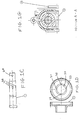
- Figure 1C is an exploded view of the ball screw rod end shown in Figure lB.
- Figure 1D is an exploded view of the output gear module of Figure lB.
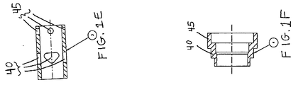
- Figure 1 E illustrates an exploded view of the sleeve portion of the linear actuator of shown in Figure 1 B.
- Figure IF illustrates an exploded view of the cup portion of the linear actuator illustrated in Figure 1B according to the present invention.
- Figure 1 G illustrates a cross-sectional view taken along Section A-A of the linear actuator shown in Figure 1 B according to the present invention.
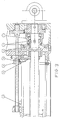
- Figure 2 illustrates a cross-sectional view of the linear actuator of the present invention in a retracted position.
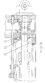
- Figure 3 illustrates a cross-sectional view of the linear actuator of the present invention in an extended position.
- Figure 4 illustrates a cross-sectional view of an alternate embodiment of the linear actuator of the present invention in an extended position without disconnection of the ball screw.
- Figure 5 is a cross-sectional view of the linear actuator according to the present invention under a limited tension load.
- Figure 6 is a cross-sectional view of the linear actuator according to the present invention under tension load set specified positions.
- Figure 7 illustrates a view of the linear actuator manually disengaged via an external handle.
- a linear actuator 100 having a disconnect mechanism and tension load limiter disposed in a housing 90 for limiting the tensile force on the shaft 1.
- the specific features of actuator 100 include shaft or ball screw rod 1 having one circular groove 20 and four axial grooves 22 on the exterior of the shaft as shown (the number of axial grooves depends on transmitted torque) in Fig. 1 C.
- Output gear 2 as will described in more detail later operates to create an axial force in a given direction for moving sleeve 3 to cause engagement of the shaft 1 with gear 12.
- Output gear 2 includes four axial grooves 31, 32, 33, 34 on its internal diameter 30, as shown in Fig 1D (Top view).
- Sleeve 3 contains four triangular shaped slots 40 and four holes 45 as shown in Fig. 1E.
- Annular cup or collar 4 contains both a small 50 and a large 55 internal diameter bores, belleville springs 5 and adapter 11.
- the ball screw rod end 1 carries a gear 12 in toothed engagement with idler gear 8 which rotates a threaded screw 9 and causes an axial movement of its nut 10 in a slot 60.
- This threaded nut operates two electrical limit switches 15 and 16 to control the stroke of the actuator.
- Torque limiter feature 89 comprising belleville springs in engagement with idler gear 8 operates to limit the torque applied to threaded screw 9.
- Ball screw rod 1 is coupled to electrically powered gear train gear 12 to cause rotation of the ball screw rod in direct response to movement of the gear.
- a shaft member mounted onto ball screw 12, such as nut 19, is translatable (i.e.
- rotatable screw 9 is positioned substantially parallel to the rotatable ball screw 1. Screw 9 is rotated by idler gear 8, which in turn is moved via gear 12. Moveable nut 10 is mounted on screw 9 such that rotation of the screw causes axial movement of nut 10 along the axis of screw 9.
- the electrical limit switches 15 and 16 are adjusted to a position within the slot so as to be in alignment with the nut 10 so that the nut engages and activates the limit switch upon reaching the corresponding axial position (i.e. 16A or 15A) which causes the corresponding switch to terminate the connection between the electrical motor 68 and the gear train 10 including the gear 12 and idler gear 8.
- Electrical connector 79 coupled through housing 90 provides electrical connectivity from a standard power source to the motor and overall linear actuator unit in conventional fashion.
- rotatable screw 9 is in parallel alignment with and rotatable in concert with the rotatable ball screw 1. Accordingly, each of the correspondingly mounted nuts 10 and 19 translate on their respective parallel axes in concert and in proportion to one another.
- the direction of axial movement of the nut 10 is opposite the direction of axial movement of ball screw nut 19.
- threaded screws 1 and 9 are separated from one another within the housing by a sufficient distance so that nuts 10 and 19 do not engage one another during translation, but rather move freely along their axes over the course of the stroke.
- the output gear 2 moves the balls 6 along the slopes of the triangular shaped slots 40 and creates an axial force which moves the sleeve 3 to the left and brings the balls 7 into the small internal diameter of the cup 4.
- the ball screw 1 is locked up with the gear train gear 12 and the actuator extends the output shaft such that movement of the gear causes rotation of the ball screw.
- the sleeve 3 shifts to the left and the ball screw engagement will occur when the actuator is commanded to retract.
- FIG. 2 provides an illustration of the actuator 100 according to the present invention in a retracted position.
- the electric power from the motor to the gear train is disconnected by the limit switch 16 engaging nut 10.
- the ball screw nut 19 mounted on ball screw rod 1 and translatable between a first extended position and a second retracted position is moved in its slot 72 into the retracted position and forceably engages adapter 11.
- Adaptor 11 translates this force to sleeve 3, which moves to the right and disengages balls 7 by positioning them into larger internal diameter of the cup 4.
- the ball screw 1 is disconnected from the gear train 12 and the actuator rod is now free to move and ready for manual operation.
- Figure 3 represents an actuator 100 in a fully extended position.
- the electric power is disconnected by the engagement of nut 10 with limit switch 15.
- the threaded auxiliary nut 10 is moved in its slot at axial position 15a and similarly shifts the sleeve 3 through adapter 11 to the right and disengages the balls 7 by positioning them into the larger internal diameter of the cup 4.
- the disconnection of the ball screw from the gear train in full extended position may be prevented by eliminating the idler gear 8, adapter 11 and the auxiliary screw 9 with its nut 10.
- the ball screw nut 19 directly operates electrical limit switches 15 and 16 to control the stroke of the actuator, as shown in Figure 4.
- the automatic disconnect mechanism incorporates two angular contact bearings 13 and 14, to take up the thrust loads right bearing - compression, left - tension. Under compression the thrust load is transmitted directly to the right bearing 14 and gear 12.
- the ball screw 1 with cup 4 by squeezing the spring 5 and together with sleeve 3 shifts to the left and then the load through output gear 2 is transmitted to the left bearing 13.
- the limit switch 15 which disconnects the electrical motor. The same switch operates to disconnect the electrical motor at the end of the travel by the moving auxiliary nut 10. This way, the tension load could be limited during retraction and along the entire stroke of the actuator.
- two limit switches may be pressed simultaneously: switch 15, by the sleeve 3, and the additional switch 20, installed at a specified location, by the moving auxiliary nut 10. If these two switches are located close to one another, then the width of the auxiliary nut should be designed to enable depression of both of them at the end of the stroke. If the required location is far from the end of the travel, or for other design considerations, an independent travel limit switch 21, could be used which would be operated by the moving ball screw nut 19 at the end of the stroke.
- the proposed design provides for an external handle (shown in Figure 1B Section A-A) to permit, if necessary, manual operation (opening or closing) when the actuator is partially extended.
- an external handle shown in Figure 1B Section A-A
- the lever 18 pushes the sleeve 3 through adapter 11 and disconnects the ball screw from gear train and allows manual operation.
Landscapes
- Engineering & Computer Science (AREA)
- General Engineering & Computer Science (AREA)
- Mechanical Engineering (AREA)
- Transmission Devices (AREA)
Applications Claiming Priority (2)
| Application Number | Priority Date | Filing Date | Title |
|---|---|---|---|
| US41422799A | 1999-10-07 | 1999-10-07 | |
| US414227 | 1999-10-07 |
Publications (3)
| Publication Number | Publication Date |
|---|---|
| EP1091470A2 true EP1091470A2 (de) | 2001-04-11 |
| EP1091470A3 EP1091470A3 (de) | 2002-03-06 |
| EP1091470B1 EP1091470B1 (de) | 2006-04-19 |
Family
ID=23640531
Family Applications (1)
| Application Number | Title | Priority Date | Filing Date |
|---|---|---|---|
| EP00850131A Expired - Lifetime EP1091470B1 (de) | 1999-10-07 | 2000-08-01 | Automatische Abschaltvorrichtung |
Country Status (3)
| Country | Link |
|---|---|
| US (1) | US20020134180A1 (de) |
| EP (1) | EP1091470B1 (de) |
| DE (1) | DE60027380T2 (de) |
Cited By (3)
| Publication number | Priority date | Publication date | Assignee | Title |
|---|---|---|---|---|
| CN103291869A (zh) * | 2013-06-29 | 2013-09-11 | 济钢集团有限公司 | 一种便于拆装的丝杠保护套 |
| EP3343056A4 (de) * | 2016-08-31 | 2019-04-24 | Zhejiang Jiecang Linear Motion Technology Co., Ltd | Elektrische schubstange |
| CN113187864A (zh) * | 2021-04-22 | 2021-07-30 | 深圳市泰道精密机电有限公司 | 一种高精密直线模组用的定位精度校准装置 |
Families Citing this family (13)
| Publication number | Priority date | Publication date | Assignee | Title |
|---|---|---|---|---|
| US6786315B1 (en) | 2003-03-28 | 2004-09-07 | Honeywell International, Inc. | Thrust reverser system with sequential torque decoupler |
| US6974107B2 (en) * | 2003-06-18 | 2005-12-13 | Honeywell International, Inc. | Thrust reverser system actuator having an integral torque limiter |
| DE102005020184B4 (de) * | 2005-04-28 | 2012-02-09 | Dewert Antriebs- Und Systemtechnik Gmbh | Linearantrieb |
| US20100050523A1 (en) * | 2008-08-26 | 2010-03-04 | Helms James M | Safety release mechanism for use with a linear motor turning a ball screw |
| DE102009055708B4 (de) * | 2009-11-26 | 2025-11-13 | Krebs & Aulich Gmbh | Elektrischer Stellantrieb |
| US8794087B2 (en) * | 2012-06-08 | 2014-08-05 | Timotion Technology Co., Ltd. | Gear motor having safety mechanism |
| US20140260733A1 (en) * | 2013-03-15 | 2014-09-18 | Fernando D. Goncalves | Systems and methods for electric controlled reach carriage |
| EP2837556B1 (de) * | 2013-08-12 | 2016-04-27 | Airbus Defence and Space GmbH | Pneumatisch aktivierte Entkoppelungsvorrichtung |
| EP2891827B1 (de) * | 2013-08-12 | 2019-06-19 | Airbus Defence and Space GmbH | Elektromechanisch betätigte Entkoppelvorrichtung für Aktuatoren |
| US10605342B2 (en) * | 2018-02-02 | 2020-03-31 | Aries Engineering Company, Inc. | Linear actuator with torque limiter mounted to a driven sprocket |
| USD855670S1 (en) * | 2018-07-17 | 2019-08-06 | Timotion Technology Co., Ltd. | Linear actuator |
| USD853460S1 (en) * | 2018-07-17 | 2019-07-09 | Timotion Technology Co., Ltd. | Linear actuator |
| CN109278986A (zh) * | 2018-09-28 | 2019-01-29 | 陕西华燕航空仪表有限公司 | 一种襟翼电动作动筒 |
Family Cites Families (17)
| Publication number | Priority date | Publication date | Assignee | Title |
|---|---|---|---|---|
| US2514227A (en) * | 1945-02-09 | 1950-07-04 | Adiel Y Dodge | Torque transmitting coupling |
| US2493232A (en) * | 1945-09-08 | 1950-01-03 | Adiel Y Dodge | Coupling |
| US2854113A (en) * | 1957-02-06 | 1958-09-30 | Barber Colman Co | Actuator and limit means therefor |
| US3258985A (en) * | 1964-03-23 | 1966-07-05 | Jordan Controls Inc | Control apparatus for valve actuator |
| GB1201574A (en) * | 1967-11-24 | 1970-08-12 | Eriksbergs Mek Verksstads Skti | Improvements in a combined overload clutch and chuck |
| DE3437269A1 (de) * | 1984-10-11 | 1986-04-17 | Emuge-Werk Richard Glimpel Fabrik für Präzisionswerkzeuge (vormals Moschkau & Glimpel), 8560 Lauf | Ueberlastkupplung, insbesondere fuer gewindeschneidfutter oder dergleichen |
| US4858481A (en) * | 1985-05-13 | 1989-08-22 | Brunswick Valve & Control, Inc. | Position controlled linear actuator |
| FR2589766B1 (fr) * | 1985-09-19 | 1994-03-25 | Etudes Realisa Outillage Ste Fse | Adapteur a changement rapide et a limiteur de couple pour mandrin de taraudage. |
| SE454454B (sv) * | 1986-09-10 | 1988-05-02 | S & L Maskin Ab | Momentkoppling spec for tapphallare |
| US4768991A (en) * | 1987-02-10 | 1988-09-06 | Sundstrand Corporation | Cylindrical low friction slip clutch |
| US4821456A (en) * | 1988-05-02 | 1989-04-18 | Hisami Nogaki | Linear mechanical drive with precise end-of-travel load positioning |
| JPH03111196A (ja) * | 1989-09-27 | 1991-05-10 | Fanuc Ltd | 産業用ロボットの伸縮軸作動機構 |
| DK151096A (da) * | 1996-12-23 | 1998-07-17 | Linak As | Lineær aktuator |
| US5916325A (en) * | 1997-04-03 | 1999-06-29 | Dresser Industries, Inc. | Actuator assembly and torque limiting system for same |
| US5832779A (en) * | 1997-04-03 | 1998-11-10 | Dresser Industries, Inc. | Actuator assembly with manual locking device |
| TW446080U (en) * | 1999-11-09 | 2001-07-11 | Hiwin Mikrosystem Corp | Stroke limiting device for linear actuator |
| DE29919877U1 (de) * | 1999-11-11 | 2001-03-15 | Dewert Antriebs- und Systemtechnik GmbH & Co KG, 32278 Kirchlengern | Elektromotorische Verstelleinrichtung |
-
2000
- 2000-08-01 DE DE60027380T patent/DE60027380T2/de not_active Expired - Lifetime
- 2000-08-01 EP EP00850131A patent/EP1091470B1/de not_active Expired - Lifetime
-
2002
- 2002-02-11 US US10/074,350 patent/US20020134180A1/en not_active Abandoned
Cited By (4)
| Publication number | Priority date | Publication date | Assignee | Title |
|---|---|---|---|---|
| CN103291869A (zh) * | 2013-06-29 | 2013-09-11 | 济钢集团有限公司 | 一种便于拆装的丝杠保护套 |
| EP3343056A4 (de) * | 2016-08-31 | 2019-04-24 | Zhejiang Jiecang Linear Motion Technology Co., Ltd | Elektrische schubstange |
| CN113187864A (zh) * | 2021-04-22 | 2021-07-30 | 深圳市泰道精密机电有限公司 | 一种高精密直线模组用的定位精度校准装置 |
| CN113187864B (zh) * | 2021-04-22 | 2024-05-07 | 深圳市泰道精密机电有限公司 | 一种高精密直线模组用的定位精度校准装置 |
Also Published As
| Publication number | Publication date |
|---|---|
| DE60027380D1 (de) | 2006-05-24 |
| EP1091470B1 (de) | 2006-04-19 |
| US20020134180A1 (en) | 2002-09-26 |
| DE60027380T2 (de) | 2007-05-10 |
| EP1091470A3 (de) | 2002-03-06 |
Similar Documents
| Publication | Publication Date | Title |
|---|---|---|
| EP1091470A2 (de) | Automatische Abschaltvorrichtung | |
| US4910419A (en) | Overload detection mechanism for motor-driven linear actuator | |
| EP0647799B1 (de) | Linearer Antrieb | |
| US4459867A (en) | Resettable force limiting device | |
| US7900530B2 (en) | Drive device | |
| US4685550A (en) | Quick disconnect mechanism | |
| US3640140A (en) | Actuator | |
| EP4063691A1 (de) | Bequem zu bedienender linearer aktuator | |
| EP1282785B1 (de) | Kupplungsbetätigungseinheit | |
| US6389915B1 (en) | Dual load path ball screw with rod end swivel | |
| US20120318082A1 (en) | Apparatus for converting a rotational movement into an axial movement | |
| GB2345946A (en) | Preventing the application of excessive torque to the output shaft of an actuator | |
| GB1585412A (en) | Brake actuating mechanisms | |
| US11473656B2 (en) | Linear actuator | |
| US4429592A (en) | Valve operator | |
| US5934433A (en) | Friction clutch having an actuator for automated operation | |
| CN114396435B (zh) | 电驱动式离合器致动器 | |
| CN117212357A (zh) | 一种离合器执行机构及车辆 | |
| US6109594A (en) | Disengageable force regulator for linear electric screwjack | |
| US11378183B2 (en) | Gearshift actuator | |
| JPH0842657A (ja) | アクチュエータ | |
| CA1299899C (en) | Rotary/linear actuator | |
| US6840133B2 (en) | Mechanical override release mechanism for cable tensioning systems | |
| CN215120444U (zh) | 一种环保气体绝缘开关柜三工位开关电机的机械离合装置 | |
| CN106409547B (zh) | 接地开关操作装置 |
Legal Events
| Date | Code | Title | Description |
|---|---|---|---|
| PUAI | Public reference made under article 153(3) epc to a published international application that has entered the european phase |
Free format text: ORIGINAL CODE: 0009012 |
|
| AK | Designated contracting states |
Kind code of ref document: A2 Designated state(s): DE FR GB Kind code of ref document: A2 Designated state(s): AT BE CH CY DE DK ES FI FR GB GR IE IT LI LU MC NL PT SE |
|
| AX | Request for extension of the european patent |
Free format text: AL;LT;LV;MK;RO;SI |
|
| PUAL | Search report despatched |
Free format text: ORIGINAL CODE: 0009013 |
|
| AK | Designated contracting states |
Kind code of ref document: A3 Designated state(s): AT BE CH CY DE DK ES FI FR GB GR IE IT LI LU MC NL PT SE |
|
| AX | Request for extension of the european patent |
Free format text: AL;LT;LV;MK;RO;SI |
|
| RIC1 | Information provided on ipc code assigned before grant |
Free format text: 7H 02K 7/06 A, 7F 16H 25/20 B |
|
| 17P | Request for examination filed |
Effective date: 20020430 |
|
| AKX | Designation fees paid |
Free format text: DE FR GB |
|
| 17Q | First examination report despatched |
Effective date: 20040920 |
|
| GRAP | Despatch of communication of intention to grant a patent |
Free format text: ORIGINAL CODE: EPIDOSNIGR1 |
|
| GRAS | Grant fee paid |
Free format text: ORIGINAL CODE: EPIDOSNIGR3 |
|
| GRAA | (expected) grant |
Free format text: ORIGINAL CODE: 0009210 |
|
| AK | Designated contracting states |
Kind code of ref document: B1 Designated state(s): DE FR GB |
|
| REG | Reference to a national code |
Ref country code: GB Ref legal event code: FG4D |
|
| REF | Corresponds to: |
Ref document number: 60027380 Country of ref document: DE Date of ref document: 20060524 Kind code of ref document: P |
|
| ET | Fr: translation filed | ||
| PLBE | No opposition filed within time limit |
Free format text: ORIGINAL CODE: 0009261 |
|
| STAA | Information on the status of an ep patent application or granted ep patent |
Free format text: STATUS: NO OPPOSITION FILED WITHIN TIME LIMIT |
|
| 26N | No opposition filed |
Effective date: 20070122 |
|
| REG | Reference to a national code |
Ref country code: FR Ref legal event code: PLFP Year of fee payment: 16 |
|
| REG | Reference to a national code |
Ref country code: FR Ref legal event code: PLFP Year of fee payment: 17 |
|
| REG | Reference to a national code |
Ref country code: FR Ref legal event code: PLFP Year of fee payment: 18 |
|
| REG | Reference to a national code |
Ref country code: FR Ref legal event code: PLFP Year of fee payment: 19 |
|
| PGFP | Annual fee paid to national office [announced via postgrant information from national office to epo] |
Ref country code: DE Payment date: 20190828 Year of fee payment: 20 Ref country code: FR Payment date: 20190826 Year of fee payment: 20 |
|
| PGFP | Annual fee paid to national office [announced via postgrant information from national office to epo] |
Ref country code: GB Payment date: 20190827 Year of fee payment: 20 |
|
| REG | Reference to a national code |
Ref country code: DE Ref legal event code: R071 Ref document number: 60027380 Country of ref document: DE |
|
| REG | Reference to a national code |
Ref country code: GB Ref legal event code: PE20 Expiry date: 20200731 |
|
| PG25 | Lapsed in a contracting state [announced via postgrant information from national office to epo] |
Ref country code: GB Free format text: LAPSE BECAUSE OF EXPIRATION OF PROTECTION Effective date: 20200731 |