EP1092097B1 - Mobile arbeitsmaschine - Google Patents
Mobile arbeitsmaschine Download PDFInfo
- Publication number
- EP1092097B1 EP1092097B1 EP99933371A EP99933371A EP1092097B1 EP 1092097 B1 EP1092097 B1 EP 1092097B1 EP 99933371 A EP99933371 A EP 99933371A EP 99933371 A EP99933371 A EP 99933371A EP 1092097 B1 EP1092097 B1 EP 1092097B1
- Authority
- EP
- European Patent Office
- Prior art keywords
- accumulator
- hydraulic
- valve
- hydraulic circuit
- lifting cylinder
- Prior art date
- Legal status (The legal status is an assumption and is not a legal conclusion. Google has not performed a legal analysis and makes no representation as to the accuracy of the status listed.)
- Expired - Lifetime
Links
- 230000033001 locomotion Effects 0.000 claims description 41
- 239000012530 fluid Substances 0.000 claims description 2
- 238000004064 recycling Methods 0.000 claims description 2
- 239000003921 oil Substances 0.000 description 45
- 238000011084 recovery Methods 0.000 description 8
- 230000000694 effects Effects 0.000 description 6
- 239000010720 hydraulic oil Substances 0.000 description 6
- 230000001133 acceleration Effects 0.000 description 3
- 230000005540 biological transmission Effects 0.000 description 3
- 230000006378 damage Effects 0.000 description 3
- 230000001419 dependent effect Effects 0.000 description 3
- 238000010586 diagram Methods 0.000 description 3
- 238000012544 monitoring process Methods 0.000 description 3
- 238000005381 potential energy Methods 0.000 description 3
- 238000004891 communication Methods 0.000 description 2
- 238000010438 heat treatment Methods 0.000 description 2
- 230000007935 neutral effect Effects 0.000 description 2
- 230000003213 activating effect Effects 0.000 description 1
- 230000004913 activation Effects 0.000 description 1
- 238000009412 basement excavation Methods 0.000 description 1
- 230000033228 biological regulation Effects 0.000 description 1
- 239000003638 chemical reducing agent Substances 0.000 description 1
- 239000000470 constituent Substances 0.000 description 1
- 230000001276 controlling effect Effects 0.000 description 1
- 239000010779 crude oil Substances 0.000 description 1
- 238000013461 design Methods 0.000 description 1
- 238000005265 energy consumption Methods 0.000 description 1
- 238000005516 engineering process Methods 0.000 description 1
- 230000007613 environmental effect Effects 0.000 description 1
- 239000000446 fuel Substances 0.000 description 1
- 230000020169 heat generation Effects 0.000 description 1
- 230000001771 impaired effect Effects 0.000 description 1
- 238000009434 installation Methods 0.000 description 1
- 238000012986 modification Methods 0.000 description 1
- 230000004048 modification Effects 0.000 description 1
- 238000013021 overheating Methods 0.000 description 1
- 230000001105 regulatory effect Effects 0.000 description 1
- 230000000717 retained effect Effects 0.000 description 1
- 238000004088 simulation Methods 0.000 description 1
- 239000013589 supplement Substances 0.000 description 1
Images




Classifications
-
- E—FIXED CONSTRUCTIONS
- E02—HYDRAULIC ENGINEERING; FOUNDATIONS; SOIL SHIFTING
- E02F—DREDGING; SOIL-SHIFTING
- E02F9/00—Component parts of dredgers or soil-shifting machines, not restricted to one of the kinds covered by groups E02F3/00 - E02F7/00
- E02F9/20—Drives; Control devices
- E02F9/22—Hydraulic or pneumatic drives
- E02F9/2217—Hydraulic or pneumatic drives with energy recovery arrangements, e.g. using accumulators, flywheels
-
- F—MECHANICAL ENGINEERING; LIGHTING; HEATING; WEAPONS; BLASTING
- F15—FLUID-PRESSURE ACTUATORS; HYDRAULICS OR PNEUMATICS IN GENERAL
- F15B—SYSTEMS ACTING BY MEANS OF FLUIDS IN GENERAL; FLUID-PRESSURE ACTUATORS, e.g. SERVOMOTORS; DETAILS OF FLUID-PRESSURE SYSTEMS, NOT OTHERWISE PROVIDED FOR
- F15B1/00—Installations or systems with accumulators; Supply reservoir or sump assemblies
- F15B1/02—Installations or systems with accumulators
-
- B—PERFORMING OPERATIONS; TRANSPORTING
- B66—HOISTING; LIFTING; HAULING
- B66F—HOISTING, LIFTING, HAULING OR PUSHING, NOT OTHERWISE PROVIDED FOR, e.g. DEVICES WHICH APPLY A LIFTING OR PUSHING FORCE DIRECTLY TO THE SURFACE OF A LOAD
- B66F9/00—Devices for lifting or lowering bulky or heavy goods for loading or unloading purposes
- B66F9/06—Devices for lifting or lowering bulky or heavy goods for loading or unloading purposes movable, with their loads, on wheels or the like, e.g. fork-lift trucks
- B66F9/075—Constructional features or details
- B66F9/20—Means for actuating or controlling masts, platforms, or forks
- B66F9/22—Hydraulic devices or systems
-
- E—FIXED CONSTRUCTIONS
- E02—HYDRAULIC ENGINEERING; FOUNDATIONS; SOIL SHIFTING
- E02F—DREDGING; SOIL-SHIFTING
- E02F9/00—Component parts of dredgers or soil-shifting machines, not restricted to one of the kinds covered by groups E02F3/00 - E02F7/00
- E02F9/20—Drives; Control devices
- E02F9/22—Hydraulic or pneumatic drives
- E02F9/2264—Arrangements or adaptations of elements for hydraulic drives
- E02F9/2267—Valves or distributors
-
- F—MECHANICAL ENGINEERING; LIGHTING; HEATING; WEAPONS; BLASTING
- F15—FLUID-PRESSURE ACTUATORS; HYDRAULICS OR PNEUMATICS IN GENERAL
- F15B—SYSTEMS ACTING BY MEANS OF FLUIDS IN GENERAL; FLUID-PRESSURE ACTUATORS, e.g. SERVOMOTORS; DETAILS OF FLUID-PRESSURE SYSTEMS, NOT OTHERWISE PROVIDED FOR
- F15B1/00—Installations or systems with accumulators; Supply reservoir or sump assemblies
- F15B1/02—Installations or systems with accumulators
- F15B1/024—Installations or systems with accumulators used as a supplementary power source, e.g. to store energy in idle periods to balance pump load
-
- F—MECHANICAL ENGINEERING; LIGHTING; HEATING; WEAPONS; BLASTING
- F15—FLUID-PRESSURE ACTUATORS; HYDRAULICS OR PNEUMATICS IN GENERAL
- F15B—SYSTEMS ACTING BY MEANS OF FLUIDS IN GENERAL; FLUID-PRESSURE ACTUATORS, e.g. SERVOMOTORS; DETAILS OF FLUID-PRESSURE SYSTEMS, NOT OTHERWISE PROVIDED FOR
- F15B11/00—Servomotor systems without provision for follow-up action; Circuits therefor
- F15B11/16—Servomotor systems without provision for follow-up action; Circuits therefor with two or more servomotors
- F15B11/17—Servomotor systems without provision for follow-up action; Circuits therefor with two or more servomotors using two or more pumps
-
- F—MECHANICAL ENGINEERING; LIGHTING; HEATING; WEAPONS; BLASTING
- F15—FLUID-PRESSURE ACTUATORS; HYDRAULICS OR PNEUMATICS IN GENERAL
- F15B—SYSTEMS ACTING BY MEANS OF FLUIDS IN GENERAL; FLUID-PRESSURE ACTUATORS, e.g. SERVOMOTORS; DETAILS OF FLUID-PRESSURE SYSTEMS, NOT OTHERWISE PROVIDED FOR
- F15B13/00—Details of servomotor systems ; Valves for servomotor systems
- F15B13/02—Fluid distribution or supply devices characterised by their adaptation to the control of servomotors
-
- F—MECHANICAL ENGINEERING; LIGHTING; HEATING; WEAPONS; BLASTING
- F15—FLUID-PRESSURE ACTUATORS; HYDRAULICS OR PNEUMATICS IN GENERAL
- F15B—SYSTEMS ACTING BY MEANS OF FLUIDS IN GENERAL; FLUID-PRESSURE ACTUATORS, e.g. SERVOMOTORS; DETAILS OF FLUID-PRESSURE SYSTEMS, NOT OTHERWISE PROVIDED FOR
- F15B21/00—Common features of fluid actuator systems; Fluid-pressure actuator systems or details thereof, not covered by any other group of this subclass
- F15B21/14—Energy-recuperation means
-
- F—MECHANICAL ENGINEERING; LIGHTING; HEATING; WEAPONS; BLASTING
- F15—FLUID-PRESSURE ACTUATORS; HYDRAULICS OR PNEUMATICS IN GENERAL
- F15B—SYSTEMS ACTING BY MEANS OF FLUIDS IN GENERAL; FLUID-PRESSURE ACTUATORS, e.g. SERVOMOTORS; DETAILS OF FLUID-PRESSURE SYSTEMS, NOT OTHERWISE PROVIDED FOR
- F15B2211/00—Circuits for servomotor systems
- F15B2211/20—Fluid pressure source, e.g. accumulator or variable axial piston pump
- F15B2211/205—Systems with pumps
- F15B2211/2053—Type of pump
- F15B2211/20546—Type of pump variable capacity
-
- F—MECHANICAL ENGINEERING; LIGHTING; HEATING; WEAPONS; BLASTING
- F15—FLUID-PRESSURE ACTUATORS; HYDRAULICS OR PNEUMATICS IN GENERAL
- F15B—SYSTEMS ACTING BY MEANS OF FLUIDS IN GENERAL; FLUID-PRESSURE ACTUATORS, e.g. SERVOMOTORS; DETAILS OF FLUID-PRESSURE SYSTEMS, NOT OTHERWISE PROVIDED FOR
- F15B2211/00—Circuits for servomotor systems
- F15B2211/20—Fluid pressure source, e.g. accumulator or variable axial piston pump
- F15B2211/205—Systems with pumps
- F15B2211/2053—Type of pump
- F15B2211/20561—Type of pump reversible
-
- F—MECHANICAL ENGINEERING; LIGHTING; HEATING; WEAPONS; BLASTING
- F15—FLUID-PRESSURE ACTUATORS; HYDRAULICS OR PNEUMATICS IN GENERAL
- F15B—SYSTEMS ACTING BY MEANS OF FLUIDS IN GENERAL; FLUID-PRESSURE ACTUATORS, e.g. SERVOMOTORS; DETAILS OF FLUID-PRESSURE SYSTEMS, NOT OTHERWISE PROVIDED FOR
- F15B2211/00—Circuits for servomotor systems
- F15B2211/20—Fluid pressure source, e.g. accumulator or variable axial piston pump
- F15B2211/205—Systems with pumps
- F15B2211/20576—Systems with pumps with multiple pumps
-
- F—MECHANICAL ENGINEERING; LIGHTING; HEATING; WEAPONS; BLASTING
- F15—FLUID-PRESSURE ACTUATORS; HYDRAULICS OR PNEUMATICS IN GENERAL
- F15B—SYSTEMS ACTING BY MEANS OF FLUIDS IN GENERAL; FLUID-PRESSURE ACTUATORS, e.g. SERVOMOTORS; DETAILS OF FLUID-PRESSURE SYSTEMS, NOT OTHERWISE PROVIDED FOR
- F15B2211/00—Circuits for servomotor systems
- F15B2211/20—Fluid pressure source, e.g. accumulator or variable axial piston pump
- F15B2211/21—Systems with pressure sources other than pumps, e.g. with a pyrotechnical charge
- F15B2211/212—Systems with pressure sources other than pumps, e.g. with a pyrotechnical charge the pressure sources being accumulators
-
- F—MECHANICAL ENGINEERING; LIGHTING; HEATING; WEAPONS; BLASTING
- F15—FLUID-PRESSURE ACTUATORS; HYDRAULICS OR PNEUMATICS IN GENERAL
- F15B—SYSTEMS ACTING BY MEANS OF FLUIDS IN GENERAL; FLUID-PRESSURE ACTUATORS, e.g. SERVOMOTORS; DETAILS OF FLUID-PRESSURE SYSTEMS, NOT OTHERWISE PROVIDED FOR
- F15B2211/00—Circuits for servomotor systems
- F15B2211/30—Directional control
- F15B2211/305—Directional control characterised by the type of valves
- F15B2211/3056—Assemblies of multiple valves
- F15B2211/30565—Assemblies of multiple valves having multiple valves for a single output member, e.g. for creating higher valve function by use of multiple valves like two 2/2-valves replacing a 5/3-valve
- F15B2211/3057—Assemblies of multiple valves having multiple valves for a single output member, e.g. for creating higher valve function by use of multiple valves like two 2/2-valves replacing a 5/3-valve having two valves, one for each port of a double-acting output member
-
- F—MECHANICAL ENGINEERING; LIGHTING; HEATING; WEAPONS; BLASTING
- F15—FLUID-PRESSURE ACTUATORS; HYDRAULICS OR PNEUMATICS IN GENERAL
- F15B—SYSTEMS ACTING BY MEANS OF FLUIDS IN GENERAL; FLUID-PRESSURE ACTUATORS, e.g. SERVOMOTORS; DETAILS OF FLUID-PRESSURE SYSTEMS, NOT OTHERWISE PROVIDED FOR
- F15B2211/00—Circuits for servomotor systems
- F15B2211/30—Directional control
- F15B2211/31—Directional control characterised by the positions of the valve element
- F15B2211/3105—Neutral or centre positions
- F15B2211/3116—Neutral or centre positions the pump port being open in the centre position, e.g. so-called open centre
-
- F—MECHANICAL ENGINEERING; LIGHTING; HEATING; WEAPONS; BLASTING
- F15—FLUID-PRESSURE ACTUATORS; HYDRAULICS OR PNEUMATICS IN GENERAL
- F15B—SYSTEMS ACTING BY MEANS OF FLUIDS IN GENERAL; FLUID-PRESSURE ACTUATORS, e.g. SERVOMOTORS; DETAILS OF FLUID-PRESSURE SYSTEMS, NOT OTHERWISE PROVIDED FOR
- F15B2211/00—Circuits for servomotor systems
- F15B2211/50—Pressure control
- F15B2211/505—Pressure control characterised by the type of pressure control means
- F15B2211/50509—Pressure control characterised by the type of pressure control means the pressure control means controlling a pressure upstream of the pressure control means
- F15B2211/50518—Pressure control characterised by the type of pressure control means the pressure control means controlling a pressure upstream of the pressure control means using pressure relief valves
-
- F—MECHANICAL ENGINEERING; LIGHTING; HEATING; WEAPONS; BLASTING
- F15—FLUID-PRESSURE ACTUATORS; HYDRAULICS OR PNEUMATICS IN GENERAL
- F15B—SYSTEMS ACTING BY MEANS OF FLUIDS IN GENERAL; FLUID-PRESSURE ACTUATORS, e.g. SERVOMOTORS; DETAILS OF FLUID-PRESSURE SYSTEMS, NOT OTHERWISE PROVIDED FOR
- F15B2211/00—Circuits for servomotor systems
- F15B2211/50—Pressure control
- F15B2211/515—Pressure control characterised by the connections of the pressure control means in the circuit
- F15B2211/5159—Pressure control characterised by the connections of the pressure control means in the circuit being connected to an output member and a return line
-
- F—MECHANICAL ENGINEERING; LIGHTING; HEATING; WEAPONS; BLASTING
- F15—FLUID-PRESSURE ACTUATORS; HYDRAULICS OR PNEUMATICS IN GENERAL
- F15B—SYSTEMS ACTING BY MEANS OF FLUIDS IN GENERAL; FLUID-PRESSURE ACTUATORS, e.g. SERVOMOTORS; DETAILS OF FLUID-PRESSURE SYSTEMS, NOT OTHERWISE PROVIDED FOR
- F15B2211/00—Circuits for servomotor systems
- F15B2211/60—Circuit components or control therefor
- F15B2211/625—Accumulators
-
- F—MECHANICAL ENGINEERING; LIGHTING; HEATING; WEAPONS; BLASTING
- F15—FLUID-PRESSURE ACTUATORS; HYDRAULICS OR PNEUMATICS IN GENERAL
- F15B—SYSTEMS ACTING BY MEANS OF FLUIDS IN GENERAL; FLUID-PRESSURE ACTUATORS, e.g. SERVOMOTORS; DETAILS OF FLUID-PRESSURE SYSTEMS, NOT OTHERWISE PROVIDED FOR
- F15B2211/00—Circuits for servomotor systems
- F15B2211/70—Output members, e.g. hydraulic motors or cylinders or control therefor
- F15B2211/71—Multiple output members, e.g. multiple hydraulic motors or cylinders
- F15B2211/7142—Multiple output members, e.g. multiple hydraulic motors or cylinders the output members being arranged in multiple groups
-
- F—MECHANICAL ENGINEERING; LIGHTING; HEATING; WEAPONS; BLASTING
- F15—FLUID-PRESSURE ACTUATORS; HYDRAULICS OR PNEUMATICS IN GENERAL
- F15B—SYSTEMS ACTING BY MEANS OF FLUIDS IN GENERAL; FLUID-PRESSURE ACTUATORS, e.g. SERVOMOTORS; DETAILS OF FLUID-PRESSURE SYSTEMS, NOT OTHERWISE PROVIDED FOR
- F15B2211/00—Circuits for servomotor systems
- F15B2211/70—Output members, e.g. hydraulic motors or cylinders or control therefor
- F15B2211/78—Control of multiple output members
- F15B2211/781—Control of multiple output members one or more output members having priority
Definitions
- Mobile handling device with hydraulic circuit which hydraulic circuit comprises a lifting cylinder arranged in a lifting device intended for handling a variable load and an accumulator for recovering or recycling the lowering load energy.
- Excavators, trucks, container handlers etc. and a large number of other mobile handling machines which are intended to handle a variable load have one or more lifting cylinders for lifting the load for which the unit is designed.
- the great majority of mobile handling devices used today have no energy recovery facility whatever for the lowering load, meaning that the lowering load energy, most often in connection with passage through a control valve which determines the lifting and lowering motion, is converted to heat which then has to be cooled away.
- the heating of the hydraulic oil to undesirable temperatures is a long familiar problem for machinery manufacturers and end customers.
- a specific problem in the field of the invention relates to mobile handling machines which are also equipped with a slewing motion for the lifting device, of the excavator type, which are equipped with a roller path and one or more hydraulic motors which transmit the force for the slewing motion by means of toothed gearing.
- Such machines have a slewing part, which in relation to the load represents a large mass, signifying a large moment of inertia which has to be overcome at each new start of a slewing motion. This makes great demands if speed is desired in the slewing motion, and it is not unusual for more than 40% of the motor power to be used for starting this.
- the pressure will rise to the maximum value and the flow increases until its desired rotation speed is attained, following which the pressure is reduced to the level required for overcoming the no-load losses.
- the movement energy attained is then braked away in machines of this kind by throttling the return flow via overflow valves, which in addition to an energy loss gives rise to not inconsiderable heating of the hydraulic medium.
- the system is also set up using a counter-pressure on the "meter in” side to prevent the movement racing away ahead of the "meter out” flow, i.e. to avoid so-called hydraulic play.
- This setting up will function in principle such that one both accelerates and brakes at the same time, which of course is very disadvantageous from the energy point of view. It is not unusual to brake away 30% of the power supplied in this manner during the slewing movement itself.
- the object of the present invention is to eliminate or at least reduce the aforementioned problems, which is achieved by means of a device according to the characterizing part of claim 1.
- the oil can be pumped directly between the accumulator and the lifting cylinder, which signifies a considerable simplification and means that control losses are eliminated in effect.
- the invention thus not only solves the heat problem, but also signifies a substantial energy saving, which surprisingly has been shown to amount to around 30%.
- a control valve in communication with said hydraulic circuit is a control valve, said variable reciprocating pump being connected to at least one of said accumulator and said lifting cylinder without the connection going via the control valve, preferably both said accumulator and said lifting cylinder being connected in such a way to the reciprocating pump.
- a system of this kind signifies a considerable simplification, not least in control terms, and means that control losses are in effect eliminated.
- the control valves in existence today are not normally made to control the flow from the consumer unit to the motor port, but are designed to control the flow from the motor port to the consumer unit. This is a disadvantage from the operator viewpoint, as no pressure compensation can take place, which means that the lifting speed is influenced by the load.
- a system according to the invention can eliminate all these disadvantages and is also more efficient.
- the hydraulic circuit comprises a first stop valve disposed in the line between one port of the hydraulic machine and the lifting cylinder, and a second stop valve disposed in the line between the second port of the hydraulic machine and the accumulator, meaning that leakage losses, which would otherwise occur in the hydraulic machine, can be eliminated during periods when the hydraulic machine is in the neutral position, i.e. when the lifting device is not intended to execute work in a vertical direction.
- said first and second stop valves are controlled by a servo circuit which comprises a servo pump and a valve unit, by means of which the stop valves are actuated into the open position when a control signal activates the changeover valve to open the connection between the accumulator and the lifting cylinder via the hydraulic machine.
- a servo circuit which comprises a servo pump and a valve unit, by means of which the stop valves are actuated into the open position when a control signal activates the changeover valve to open the connection between the accumulator and the lifting cylinder via the hydraulic machine.
- said cylinder is of the double-acting type comprising a rod side and a cylinder side, the side which is not directly connected to the hydraulic machine being able to receive oil from a hydraulic pump via a control regulator.
- the hydraulic circuit comprises a second accumulator, which is connected via at least one nonreturn valve to at least one of the lines between the accumulator and the hydraulic machine or the hydraulic machine and the lifting cylinder.
- the hydraulic circuit with the lifting cylinder and the accumulator communicates with a second hydraulic circuit for a slewing turning device, which second circuit comprises valve elements which in connection with deceleration of said slewing part supplies hydraulic fluid to said accumulator, whereupon this is filled and at the same time acts on the slewing part with a decelerating force.
- Fig. 1 shows a hydraulic scheme for a lifting cylinder in a hydraulic circuit according to the invention.
- a double-acting hydraulic cylinder 1, variable reciprocating pump 3 (which is called a hydraulic machine below) and an accumulator 6 are shown.
- the hydraulic circuit is disposed in a mobile handling device, for example a truck or excavator, the lifting cylinder 1 thus being provided to carry out vertical work in the handling device's lifting device, for example the arm which carries the bucket on an excavator.
- a logic element 2 Disposed between the lifting cylinder 1 and the hydraulic machine 3 is a logic element 2, in the form of a stop valve, which is spring-loaded and which in its uninfluenced state breaks the connection between the hydraulic machine 3 and the lifting cylinder 1.
- valve device 2 In its activated position, the valve device 2 gives open communication between the hydraulic machine 3 and the lifting cylinder 1.
- This logic element 2 also preferably functions as a tube-breaking element
- a similar logic element 5 is disposed between the accumulator 6 and the hydraulic motor 3, with a function similar to the first-named logic element 2. This too is in the form of a stop valve 2.
- Both these valve devices 2, 5 are controlled by means of a servo system 4, 9, consisting of a servo pump 4 and a valve 9.
- the servo pump 4 is operated by an independent source, normally the handling device's fuel-based motor D, which appropriately also drives the variable reciprocating pump 3. Operation takes place in a known manner via a suitable transmission.
- the hydraulic flow from the servo pump 4 can act via the valve 9 on the logic elements 2, 5 to open the connection in the respective line 3-1, 3-6.
- the servo valve 9 is normally controlled by an operator, if applicable by an automatic monitoring system, in such a manner that when it is desired to carry out work with the lifting cylinder 1, the servo valve 9 is actuated to open the connection between the pressure side of the servo pump 4 and the lines 9-2, 9-5, which lead to the logic elements 2, 5, so that the oil pressure is supplied when these open.
- the hydraulic machine 3 is a variable reciprocating pump which can both receive and emit oil at the ports 10, 11.
- the pump is of a known type which permits full system pressure at both outlet ports and in which the flow can be adjusted from 0 - max. by means of the variable setting, which is normally achieved by means of a so-called swash plate.
- Using a pump of this kind eliminates the need to regulate the circuit via a control valve, whereby a considerable simplification is achieved at the same time as control losses are practically eliminated.
- a sequential valve 7 is included in the hydraulic circuit.
- the sequential valve 7 is disposed in a line 1-6, which connects the lifting cylinder 1 to the accumulator 6, by means of which it is possible to relieve any excess pressure in the line 1-2 between the lifting cylinder and the logic element 2 via the sequential valve 7 to the accumulator 6, so that the energy is retained in the system.
- a safety valve 8 is provided in the system between the accumulator 6 and a tank 42, which ensures that a certain maximum pressure for the circuit is not exceeded.
- a pressure-reducing valve 23 is disposed between the accumulator 6 and the logic element 5. The pressure-reducing valve ensures that the accumulator pressure does not exceed the maximum value permitted for the accumulator type, meaning that the accumulator does not necessarily need to be of the same pressure class as the rest of the system.
- the hydraulic circuit is connected to the handling device's conventional hydraulic pump 12, the flow of which is regulated in a conventional manner via a control valve 13. Due to this, oil can be routed via one of the ports 14 on the control valve 13 to the opposite side 1 A of the double-acting cylinder 1. Furthermore, oil can be supplied via the control valve 13 via a second port 15 to the piston side I B of the lifting cylinder 1. In the line 15-1, disposed between the control valve 13 and the piston side 1 B of the lifting cylinder 1 is a nonreturn valve 16 which prevents oil being routed from the piston side 1 B of the lifting cylinder to the control valve 13.
- the hydraulic pump 12 collects its oil in the normal manner from the tank 42.
- the control valve 13 is normally connected by one end 13-42 to the tank 42, while its other end 13-12 is connected to the hydraulic pump 12. Furthermore, the system has a sequential valve 19 which can return surplus oil from the lifting circuit 1, 3, 6 to the control valve 13, where it can be used for example to manoeuvre the stick on an excavator. Finally, it is shown that the system can include a further accumulator 21, which can either be disposed to be connected or not connected to the circuit via a valve 22. This extra accumulator 21 can be used either to ensure that sufficient hydraulic oil is to be found in connection with certain working operations and/or to provide the circuit with a different pressure level in connection with certain working operations.
- a pressure-sensing element 17 is provided to be able to register the pressure in the line between the lifting cylinder I and the logic element 2. In the event of a lowering motion which requires power, the pressure-sensing element 17 will register that the pressure is below that required for the function and ensure that the control valve 13 emits oil to the rod side of the lifting cylinder via port 14.
- the system functions such that in the event of a lifting movement, the operator will send a control signal to the control servo (not shown), which will activate the valve 9 which in turn ensures that the valves 2 and 5 open.
- the connection between the accumulator 6, hydraulic machine 3 and lifting cylinder 1 is thus completely open.
- the pressurized oil in the accumulator 6 flows then to the variable hydraulic machine 3, which conveys the oil onwards to the lifting cylinder 1. If the pressure in the accumulator in this case is higher than that required to carry out the work using the lifting cylinder 1, the surplus energy will be supplied by the hydraulic machine 3 to the drive system, best achieved via the transmission T.
- variable hydraulic machine 3 provides a pressure increase to reach the requisite pressure level, which is achieved by means of power which is supplied via the handling machine's motor D. Thus in such a situation only as much energy is supplied as is required to overcome the pressure difference between the accumulator and the lifting cylinder's requirement.
- the direction of flow in the pump is changed and oil is supplied at port 10 and emitted at port 11 to be supplied to the accumulator 6. If the pressure in the accumulator 6 is then lower than at the lifting cylinder 1, the variable hydraulic machine 3 will be able to supply energy to the transmission T.
- the task of the pressure-sensing element 17 is to ensure that the hydraulic machine 3 adjusts the flow down to 0 when the hydraulic cylinder no longer has any pressure, for example when the bucket has reached ground level.
- both the variable hydraulic machine 3 and the hydraulic pump 12 can be activated, in which case the oil obtained from the accumulator does not fully correspond to the quantity of oil of the lifting cylinder.
- the nonreturn valve 16 will prevent the oil from flowing to port 15.
- an amount corresponding to that obtained from the pump 12 must be evacuated from the circuit through the safety valve 8.
- the sequential valve 19 can be used to return the surplus oil to the inlet side of the control valve 13, to be used for example for the slewing motion on an excavator.
- Oil for the rod side of the double-acting lifting cylinder 1 can be obtained via a so-called refill valve 18, in the form of a nonreturn valve, which is disposed between the outlet side of the control valve and the line 14-1 which leads to the rod side of the lifting cylinder 1.
- Fig. 2 shows a preferred hydraulic scheme for a hydraulic circuit according to the invention.
- This shows a hydraulic circuit which in total consists basically of the same sub-components as described in Fig. 1. Only the essential differences will therefore be described below.
- a further accumulator 20 is provided connected to the circuit.
- This further accumulator 20 has a lower system pressure than the main accumulator 6.
- the second accumulator 20 is connected to the main system 6, 3, 1 via nonreturn valves 30, 31, 32.
- a first line 2-20 is connected to the line between the logic element 2 and the top port 10 of the hydraulic machine 3 via a first nonreturn valve 30.
- a second line 5-20 is connected to the line between the accumulator 6 and the logic element 5 via a second nonreturn valve 32.
- the two lines are brought together to the opening side of a common nonreturn valve 31 which is connected via its closing side to the accumulator 20.
- the task of this additional accumulator 20 is to be able to supply oil instantaneously to the variable reciprocating pump 3 when urgently required. An urgent requirement of this kind arises when the main accumulator 6 becomes empty. Emptying of the main accumulator 6 takes place namely instantaneously in the course of a very short space of time without any actual advance warning that the quantity of oil is about to run out.
- the conventional hydraulic pump 12 does not manage in this case to deliver oil in the short time which is available, meaning that a risk of total destruction of the variable reciprocating pump exists.
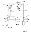
- Fig. 3 shows in diagrammatic form a hydraulic circuit for a handling machine (not shown) which has a slewing crane or the like (not shown), the slewing motions of which are activated by means of a hydraulic slewing motor 35. Also connected to the hydraulic circuit communicatingly for activating slewing of the arm is a lifting circuit L. Provided for this lifting circuit in a known manner is an accumulator 6 which is thus intended to utilize the potential energy of the arm system and the load on lowering.
- the slewing circuit which consists of the pump 12, control regulator 13, slewing motor 35, are two sequential valves 36, 37, which via a nonreturn valve 38 feed the surplus oil occurring on deceleration to the accumulator 6 located in the lifting circuit L.
- the sequential valves 36, 37 are set by means of springs 46, 47, which means that a certain minimum pressure must exist in the forward line to the valve 36, 37 for this to be activated so that oil can pass to the accumulator tank 6.
- each sequential valve 36, 37 is connected via the line 43, 48 to a respective servo cover 44, 45 on the control regulator 13, which means that existing pressure in the servo cover 44, 45 is superimposed, together with the spring pressure at the sequential valve 36, 37.
- Located in the control regulator 13 in a known manner are pressure-reducing valves/overflow valves (not shown), which can be adjusted from being completely open to completely closed.
- the pump 12 feeds oil to one side P of the control regulator 13.
- a return line 43 which is not pressurized and leads to the tank 42.
- Three other functions are provided in the case of the control regulator shown in Fig. 3. Each of these functions is controlled in a known manner by means of a slide valve. The figure only shows the circuit which is connected to the slide valve which actuates the slewing motor 35. Thus a top port is shown, the so-called A port, which provides slewing in one direction, and a lower port, the so-called B port, which provides slewing in another direction.
- the control valve In a slewing motion, the control valve is activated by a servo (not shown) which causes oil to be sent from the pump 12 via the control regulator 13 to the slewing motor 35. If the control valve is activated so that the A port is opened, in that case the oil pressure from the pump 12 will be supplied on the one hand on the A-side to the slewing motor 35, and also via the servo cover to the line 43 which effects the actuating pressure for the sequential valve 36. Thus the sequential valve 36 will thereby be kept closed during the acceleration phase, due to which all oil will be supplied and flow through the hydraulic motor 35.
- the deceleration work will instead be utilized due to the fact that the braking energy is supplied to the accumulator tank 6.
- This is achieved by the pressurized hydraulic oil being supplied to the accumulator 6 via the sequential valve 37 or 36. Due to the fact that the pressure in the servo line 48 is reduced during the deceleration movement, the sequential valve 37 will open the connection to the accumulator 6 before the overflow valve has opened. Due to the fact that the accumulator pressure 6 is slightly below the deceleration pressure of the slewing motor 35, the deceleration energy will be supplied to the accumulator 6 practically intact. The energy loss is determined by the pressure difference between the two communicating levels. If a conventional system is used, in which one level is atmospheric pressure and e.g.
- the pressure level at the slewing circuit's pressure reducer is set at 210 bar
- the flow x 210 will equal the energy loss.
- the only loss will be the difference between the accumulator pressure and the pressure level of the sequential valve. If the pressure in the accumulator for example is 160 bar and the lowest pressure in the sequential valve is 180 bar, the energy loss will be 20 x flow, i.e. approx. 10% compared to a conventional arrangement.. If the accumulator pressure during deceleration rises to 210, the loss will be close to zero.
- the sequential valves 36, 37 are proportionally controlled inside the pressure level which the servo covers require or approx. 40 bar in excess of the basic setting of the sequential valve.
- a refilling circuit (not shown) is provided in the control regulator 13, the object of which circuit is to eliminate the occurrence of hydraulic play.
- Fig. 3 offers several major advantages in addition to the energy-saving function, of which the most important is that heat generation is reduced drastically.
- All known overflow valves are based on the fact that the pressure of the hydraulic medium is reduced via throttling, the energy loss arising in this case being converted to heat.
- the pressure drop will in principle be virtually eliminated as the accumulator pressure differs negligibly from the maximum pressure of the slewing circuit, meaning that the heat increase is eliminated in principle.
- the temperature in the outlet of a pressure-reducing nozzle is directly dependent on the pressure difference. In a high pressure drop, 2-300 bar, which conventionally exists, the outlet temperature will be several hundred degrees, which has a negative effect on the life of the hydraulic medium.
- Fig. 4 shows a hydraulic scheme of a preferred combination of a slewing circuit 5 [sic] and a lifting circuit L forming part of an excavator, for example.
- the lifting cylinder 1 is connected in this case to the excavator bucket arm (not shown) and the slewing motor 35 is connected to the excavator bucket's slewing circuit (not shown).
- the preferred embodiment shown in Fig. 2 is used in the lifting circuit L, with an extra accumulator 20 to ensure the necessary oil flow to the variable hydraulic machine 3 even when the main accumulator 6 is emptied.
- the system in principle is a combination of Fig. 2 and 3.
- Fig. 5 shows in schematic form a diagram which illustrates an energy saving which can be achieved when using a lifting circuit according to the invention (i.e. according to Fig. 1 or 2).
- the momentary power consumption is shown on the y-axis and on the x-axis a time axis is shown.
- the curves simulate one and the same job carried out by an excavator, in which one curve A describes the power consumption in a standard system and the other curve B describes the power consumption with a system according to the invention.
- the simulation is based on a frequently occurring operation for excavator buckets involving first extending the bucket arm, then driving the bucket down into the ground, then contracting the arm, whereupon the bucket is filled, following which the bucket is lifted up and a slewing movement begun (power peak according to old system). Following this, the slewing movement is decelerated, the goods are dropped from the bucket, after which the bucket is finally lowered. It is obvious that the energy consumption is considerably greater for a standard system, approx. 40% during the most work-intensive phase (between two and sixteen seconds). A marked energy saving can thus be made thanks to the fact that oil at charging pressure from the accumulator can be reused. If the combination according to Fig. 4 is used in addition, the saving is even greater.
- the invention is not restricted to that demonstrated above but can be varied within the scope of the following patent claims. It is perceived for example that the servo pressure can be obtained from a source in the system other than the pump 4, e.g. from the accumulator 20. It is furthermore perceived that one is not limited in any way to using just one lifting cylinder but that also two or more lifting cylinders can be used in a circuit according to the invention. The same is naturally true also of the number of accumulators, which can be varied as desired or needed. It is also perceived that a number of modifications can be made with regard to the valve arrangements without it affecting the principles of the invention.
- the invention can also be used in similar handling machines other than those previously named, for example forestry machines, so-called croppers etc.
- the invention can also be utilized in connection with the use of a control valve via which the hydraulic oil is routed to and from the accumulator or lifting cylinder.
- a control valve via which the hydraulic oil is routed to and from the accumulator or lifting cylinder.
- the potential energy which is in the lifting piston will in the event of a lowering movement be returned to the accumulator via the control valve, which accumulator in turn is connected to the variable reciprocating pump.
- a precondition however is that the accumulator pressure is below the lifting cylinder pressure and that before a state of equilibrium arises a separate return line to the tank is opened.
- the pressurized oil in the accumulator will provide the pressure increase or pressure drop in the reciprocating pump necessary for the requirement to execute the desired work.
- the control valve is supplied with hydraulic medium from the lifting pistons via regular pump inlet and that the control valve is provided with pressure compensation which on activation of the valve emits a pressure-compensated flow to the motor port.
Landscapes
- Engineering & Computer Science (AREA)
- General Engineering & Computer Science (AREA)
- Mechanical Engineering (AREA)
- Structural Engineering (AREA)
- Physics & Mathematics (AREA)
- Fluid Mechanics (AREA)
- Civil Engineering (AREA)
- Chemical & Material Sciences (AREA)
- Transportation (AREA)
- Mining & Mineral Resources (AREA)
- Analytical Chemistry (AREA)
- Combustion & Propulsion (AREA)
- Life Sciences & Earth Sciences (AREA)
- Geology (AREA)
- Fluid-Pressure Circuits (AREA)
- Operation Control Of Excavators (AREA)
Claims (13)
- Mobile Handhabungsvorrichtung mit hydraulischem Kreislauf, wobei der hydraulische Kreislauf (L) einen Hubzylinder (1), der in einer Hebevorrichtung (100) angeordnet ist, die geeignet ist, eine variable Last zu handhaben, und einen Akkumulator (6) zur Rückgewinnung oder Rückführung abnehmender Lastenergie umfasst, wobei der hydraulische Kreislauf ebenso eine variable hydraulische Maschine (3) mit zwei Anschlüssen (10, 11) umfasst, wobei die hydraulische Maschine mittels einer Antriebseinheit (D) in der Lage ist, einen vollen Systemdruck in zwei Flussrichtungen an die Anschlüsse abzugeben, wobei ein Anschluss (11) mit dem Akkumulator (6) verbunden ist, und der andere Anschluss mit dem Hubzylinder (1) verbunden ist, dadurch gekennzeichnet, dass ein Steuerventil (13) mit dem hydraulischen Kreislauf (L) verbunden ist, die variable hydraulische Maschine (3) mit mindestens einem von dem Akkumulator (6) und dem Hubzylinder (1) verbunden ist, ohne dass die Verbindung durch das Steuerventil (13) geht, und dass der hydraulische Kreislauf (L) einen zweiten Akkumulator (20) umfasst, der durch mindestens ein Rückschlagventil (31) mit mindestens einer der Leitungen zwischen dem Akkumulator (6) und der hydraulischen Maschine (3) oder der hydraulischen Maschine (3) und dem Hubzylinder (1) verbunden ist.
- Mobile Handhabungsvorrichtung gemäß Anspruch 1, dadurch gekennzeichnet, dass sowohl der Akkumulator als auch der Hubzylinder (1) eine solche Verbindung mit der Hubkolbenpumpe (3) aufweisen, d.h. ohne dass die Verbindung durch ein Steuerventil (13) geht.
- Mobile Handhabungsvorrichtung mit hydraulischem Kreislauf gemäß Anspruch 2, dadurch gekennzeichnet, dass der hydraulische Kreislauf (L) ein erstes Absperrventil (2) umfasst, das in der Leitung zwischen einem Anschluss (10) des hydraulischen Motors und dem Hubzylinder (1) angeordnet ist, und ein zweites Absperrventil (5), das in der Leitung zwischen dem zweiten Anschluss (11) des hydraulischen Motors und dem Akkumulator (6) angeordnet ist.
- Mobile Handhabungsvorrichtung mit hydraulischem Kreislauf gemäß Anspruch 3, dadurch gekennzeichnet, dass das erste (2) und das zweite (5) Absperrventil durch eine Servoschaltung (4, 9) gesteuert werden, die eine Servopumpe (4) und eine Ventileinheit (9) umfasst, wodurch die Absperrventile (2, 5) in die offene Stellung bewegt werden, wenn ein Steuersignal das Umschaltventil (9) aktiviert, um die Verbindung zwischen dem Akkumulator (6) und dem Hubzylinder durch die hydraulische Maschine (3) zu öffnen.
- Mobile Handhabungsvorrichtung mit hydraulischem Kreislauf gemäß Anspruch 2, dadurch gekennzeichnet, dass der Hubzylinder (1) von der doppeltwirkenden Art ist, umfassend eine Stangenseite (1A) und eine Zylinderseite (1B), wobei die Seite (1A), die nicht direkt mit dem hydraulischen Motor (3) verbunden ist, in der Lage ist, Öl von einer hydraulischen Pumpe (12) über einen Steuerregulator (13) zu erhalten.
- Mobile Handhabungsvorrichtung mit hydraulischem Kreislauf gemäß Anspruch 1, dadurch gekennzeichnet, dass der zweite Akkumulator (20) durch mindestens ein, bevorzugt zwei, Rückschlagventile (31-32, 31-30) sowohl mit der Leitung zwischen dem Akkumulator (6) und dem Motor (3) als auch der Leitung zwischen dem Motor (3) und dem Hubzylinder (1) verbunden ist.
- Mobile Handhabungsvorrichtung mit hydraulischem Kreislauf gemäß irgendeinem der vorhergehenden Ansprüche, dadurch gekennzeichnet, dass in direkter Verbindung mit dem Hubzylinder (1) ein Druckregler (17) angeordnet ist.
- Mobile Handhabungsvorrichtung mit hydraulischem Kreislauf gemäß Anspruch 1, dadurch gekennzeichnet, dass der Systemdruck in dem zweiten Akkumulator (20) deutlich niedriger ist als in dem ersten Akkumulator (6).
- Mobile Handhabungsvorrichtung mit hydraulischem Kreislauf gemäß Anspruch 1, dadurch gekennzeichnet, dass der hydraulische Kreislauf (L) mit einem zweiten hydraulischen Kreislauf (S) für eine Schwenkdrehvorrichtung (5) verbunden ist, wobei der zweite Kreislauf (S) Ventilelemente (36, 37) umfasst, die in Verbindung mit einer Verzögerung des Schwenkteils dem Akkumulator (6) Hydraulikflüssigkeit zuführen, wobei dieser gefüllt wird und gleichzeitig mit einer verzögernden Kraft auf den Schwenkteil einwirkt.
- Mobile Handhabungsvorrichtung mit hydraulischem Kreislauf gemäß Anspruch 9, dadurch gekennzeichnet, dass die Ventilelemente (36, 37) aus sequenziellen Ventilen bestehen.
- Mobile Handhabungsvorrichtung mit hydraulischem Kreislauf gemäß Anspruch 9, dadurch gekennzeichnet, dass ein Rückschlagventil (38) in der Leitung zwischen den Ventilelementen (36, 37) und dem Akkumulator (6) angeordnet ist.
- Mobile Handhabungsvorrichtung mit hydraulischem Kreislauf gemäß Anspruch 10, dadurch gekennzeichnet, dass die sequenziellen Ventile (36, 37) proportional gesteuert werden, so dass die Verzögerungsgeschwindigkeit durch das Druckniveau des Ventils gesteuert wird.
- Mobile Handhabungsvorrichtung mit hydraulischem Kreislauf gemäß Anspruch 8, dadurch gekennzeichnet, dass die Abflussleitungen (43, 48) der Ventilelemente mit Servodeckeln eines Steuerventils für die Schwenkbewegung verbunden sind, so dass die sequenziellen Ventile (36, 37) einen Steuerdruck empfangen, der durch den Druck in dem Verzögerungskreislauf beeinflusst wird.
Applications Claiming Priority (7)
| Application Number | Priority Date | Filing Date | Title |
|---|---|---|---|
| SE9802323A SE9802323D0 (sv) | 1998-06-27 | 1998-06-27 | Kolvpump system med ackumulator |
| SE9802323 | 1998-06-27 | ||
| SE9802869 | 1998-08-25 | ||
| SE9802869A SE521009C2 (sv) | 1998-08-25 | 1998-08-25 | Lyftcylinder i slutet system |
| SE9901176 | 1999-03-31 | ||
| SE9901176A SE9901176D0 (sv) | 1999-03-31 | 1999-03-31 | Energisparsystem för hanteringsmaskiner med svängrörelse |
| PCT/SE1999/001131 WO2000000748A1 (en) | 1998-06-27 | 1999-06-23 | Mobile working machine |
Publications (2)
| Publication Number | Publication Date |
|---|---|
| EP1092097A1 EP1092097A1 (de) | 2001-04-18 |
| EP1092097B1 true EP1092097B1 (de) | 2004-09-22 |
Family
ID=27355929
Family Applications (1)
| Application Number | Title | Priority Date | Filing Date |
|---|---|---|---|
| EP99933371A Expired - Lifetime EP1092097B1 (de) | 1998-06-27 | 1999-06-23 | Mobile arbeitsmaschine |
Country Status (7)
| Country | Link |
|---|---|
| US (1) | US6584769B1 (de) |
| EP (1) | EP1092097B1 (de) |
| JP (1) | JP2002519597A (de) |
| KR (1) | KR20010071622A (de) |
| AU (1) | AU4943699A (de) |
| DE (1) | DE69920452T2 (de) |
| WO (1) | WO2000000748A1 (de) |
Families Citing this family (63)
| Publication number | Priority date | Publication date | Assignee | Title |
|---|---|---|---|---|
| DE19939796C1 (de) * | 1999-08-21 | 2000-11-23 | Orenstein & Koppel Ag | Verfahren und Arbeitsmaschine zur Herstellung von Bodenflächen |
| SE521308C2 (sv) | 1999-12-27 | 2003-10-21 | Bruun Ecomate Ab | Mobil hanteringsanordning med hydraulkrets |
| DE10006013A1 (de) * | 2000-02-11 | 2001-08-23 | Hydac Technology Gmbh | Vorrichtung zur Energieeinsparung bei hydraulisch betätigbaren Arbeitsgerätschaften |
| IL154186A0 (en) * | 2000-08-18 | 2003-07-31 | Bucher Hydraulics Ag | Hydraulic lift with an accumulator |
| SE523397C2 (sv) * | 2001-05-22 | 2004-04-13 | Bruun Ecomate Ab | Mobil hanteringsanordning |
| SE519970C2 (sv) * | 2001-09-07 | 2003-05-06 | Bruun Ecomate Ab | Hydrauldrivet armsystem med flytreglering |
| US6655136B2 (en) | 2001-12-21 | 2003-12-02 | Caterpillar Inc | System and method for accumulating hydraulic fluid |
| US6748738B2 (en) | 2002-05-17 | 2004-06-15 | Caterpillar Inc. | Hydraulic regeneration system |
| JP2004011168A (ja) * | 2002-06-04 | 2004-01-15 | Komatsu Ltd | 建設機械 |
| US6789387B2 (en) | 2002-10-01 | 2004-09-14 | Caterpillar Inc | System for recovering energy in hydraulic circuit |
| US6854268B2 (en) | 2002-12-06 | 2005-02-15 | Caterpillar Inc | Hydraulic control system with energy recovery |
| JP4667801B2 (ja) * | 2004-09-10 | 2011-04-13 | 日本輸送機株式会社 | 油圧システム及びこれを備えたフォークリフト |
| US7124576B2 (en) * | 2004-10-11 | 2006-10-24 | Deere & Company | Hydraulic energy intensifier |
| DE102004061559A1 (de) * | 2004-12-21 | 2006-06-29 | Brueninghaus Hydromatik Gmbh | Hydraulischer Antrieb |
| US7269944B2 (en) * | 2005-09-30 | 2007-09-18 | Caterpillar Inc. | Hydraulic system for recovering potential energy |
| US7234298B2 (en) * | 2005-10-06 | 2007-06-26 | Caterpillar Inc | Hybrid hydraulic system and work machine using same |
| DE102006020441B4 (de) * | 2006-05-03 | 2017-01-26 | Bucyrus Hex Gmbh | Verfahren zur Lastminderung eines oder mehrerer Motore in einem Groß-Hydraulikbagger |
| US7478489B2 (en) * | 2006-06-01 | 2009-01-20 | Deere & Company | Control system for an electronic float feature for a loader |
| JP2008014468A (ja) * | 2006-07-10 | 2008-01-24 | Shin Caterpillar Mitsubishi Ltd | 作業機械における油圧制御システム |
| JP4753307B2 (ja) * | 2006-07-11 | 2011-08-24 | キャタピラー エス エー アール エル | 作業機械における油圧制御システム |
| US7631738B2 (en) | 2006-10-31 | 2009-12-15 | Caterpillar Inc. | Fluidly actuated sprag |
| US7497156B2 (en) * | 2006-10-31 | 2009-03-03 | Caterpillar Inc. | Fluid motor |
| US20080156596A1 (en) * | 2006-12-28 | 2008-07-03 | Caterpillar Inc. | Sprag and bearing system |
| US20080155976A1 (en) * | 2006-12-28 | 2008-07-03 | Caterpillar Inc. | Hydraulic motor |
| US8544264B2 (en) * | 2007-03-14 | 2013-10-01 | Deere & Company | Pump flow control of hydraulic circuit and associated method |
| US7578127B2 (en) * | 2007-04-10 | 2009-08-25 | Deere & Company | Flow continuity for multiple hydraulic circuits and associated method |
| US7634911B2 (en) | 2007-06-29 | 2009-12-22 | Caterpillar Inc. | Energy recovery system |
| DE202007011783U1 (de) * | 2007-08-23 | 2008-12-24 | Liebherr-France Sas, Colmar | Hydraulikantrieb insbesondere eines Baggers insbesondere für ein Drehwerk |
| DE102007062889A1 (de) * | 2007-12-28 | 2009-07-02 | Robert Bosch Gmbh | Antriebssystem |
| US20110064706A1 (en) * | 2008-01-11 | 2011-03-17 | U.S. Nutraceuticals, Llc D/B/A Valensa International | Method of preventing, controlling and ameliorating urinary tract infections and supporting digestive health by using a synergistic cranberry derivative, a d-mannose composition and a proprietary probiotic blend |
| DE602008004099D1 (de) * | 2008-04-29 | 2011-02-03 | Parker Hannifin Ab | Anordnung zum Bedienen einer hydraulischen Vorrichtung |
| DE202009004071U1 (de) * | 2009-03-23 | 2010-08-12 | Liebherr-France Sas, Colmar | Antrieb für einen Hydraulikbagger |
| DE102009035216A1 (de) | 2009-07-29 | 2011-02-10 | Robert Bosch Gmbh | Drehwerksantrieb |
| US20110056192A1 (en) * | 2009-09-10 | 2011-03-10 | Robert Weber | Technique for controlling pumps in a hydraulic system |
| US20110056194A1 (en) * | 2009-09-10 | 2011-03-10 | Bucyrus International, Inc. | Hydraulic system for heavy equipment |
| KR101637573B1 (ko) * | 2009-12-24 | 2016-07-08 | 두산인프라코어 주식회사 | 건설장비의 펌프제어 작동시스템 |
| KR101637572B1 (ko) * | 2009-12-24 | 2016-07-08 | 두산인프라코어 주식회사 | 건설장비의 펌프제어 작동시스템 |
| DE102010012975A1 (de) * | 2010-03-22 | 2011-09-22 | Hydac Technology Gmbh | Hydrostatisches Hybrid-Antriebssystem |
| US8362629B2 (en) * | 2010-03-23 | 2013-01-29 | Bucyrus International Inc. | Energy management system for heavy equipment |
| DE102010040754A1 (de) | 2010-09-14 | 2012-03-15 | Zf Friedrichshafen Ag | Hydraulische Antriebsanordnung |
| US8626403B2 (en) | 2010-10-06 | 2014-01-07 | Caterpillar Global Mining Llc | Energy management and storage system |
| US8718845B2 (en) | 2010-10-06 | 2014-05-06 | Caterpillar Global Mining Llc | Energy management system for heavy equipment |
| US8606451B2 (en) | 2010-10-06 | 2013-12-10 | Caterpillar Global Mining Llc | Energy system for heavy equipment |
| US9422141B2 (en) | 2010-10-22 | 2016-08-23 | Tld Canada Inc. | System and method for managing a current flow in a lift machine |
| US9279236B2 (en) | 2012-06-04 | 2016-03-08 | Caterpillar Inc. | Electro-hydraulic system for recovering and reusing potential energy |
| US8997476B2 (en) | 2012-07-27 | 2015-04-07 | Caterpillar Inc. | Hydraulic energy recovery system |
| US9190852B2 (en) | 2012-09-21 | 2015-11-17 | Caterpillar Global Mining Llc | Systems and methods for stabilizing power rate of change within generator based applications |
| US9290912B2 (en) * | 2012-10-31 | 2016-03-22 | Caterpillar Inc. | Energy recovery system having integrated boom/swing circuits |
| JP6090781B2 (ja) | 2013-01-28 | 2017-03-08 | キャタピラー エス エー アール エル | エンジンアシスト装置および作業機械 |
| US9290911B2 (en) | 2013-02-19 | 2016-03-22 | Caterpillar Inc. | Energy recovery system for hydraulic machine |
| US20150219126A1 (en) * | 2014-02-06 | 2015-08-06 | Caterpillar Inc. | Multi-Function Hydraulic Hybrid Swing Circuit |
| DE102014218886B3 (de) * | 2014-09-19 | 2015-11-12 | Voith Patent Gmbh | Hydraulischer Antrieb mit Eilhub und Lasthub |
| CN104454683B (zh) * | 2014-11-13 | 2016-08-31 | 浙江大学 | 一种基于液容储能的新型液压变压装置 |
| CN105805066B (zh) * | 2016-05-06 | 2017-07-25 | 同济大学 | 双马达型液压起网绞车能量回收试验台 |
| CN108138818B (zh) * | 2016-09-29 | 2020-06-23 | 日立建机株式会社 | 液压驱动装置 |
| IT201700075075A1 (it) * | 2017-07-04 | 2019-01-04 | Flii Vismara S R L | Sistema idraulico a bassa potenza per la movimentazione verticale di una cabina o di una piattaforma per la movimentazione di persone e/o cose |
| CN108591144B (zh) * | 2018-07-02 | 2023-07-25 | 福建工程学院 | 电机驱动双定量泵双蓄能器的分布式直驱挖掘机液压系统 |
| IT201800007019A1 (it) * | 2018-07-09 | 2020-01-09 | Impianto fluidodinamico per l'azionamento controllato della slitta di una pressa | |
| CN109185248B (zh) * | 2018-10-31 | 2023-11-21 | 湖南农业大学 | 一种用于高地隙植保机自适应调平底盘的调平系统及其调平方法 |
| CN111237264B (zh) * | 2020-02-26 | 2024-11-29 | 浙江迦南科技股份有限公司 | 用于实现双作用油缸精确控制的油路结构 |
| CN111795016B (zh) * | 2020-04-30 | 2022-08-12 | 武汉船用机械有限责任公司 | 用于油缸控制的液压系统 |
| CN116494941B (zh) * | 2023-05-11 | 2025-09-19 | 三一重型装备有限公司 | 制动阀组、液压制动系统和工程机械 |
| CN118582436B (zh) * | 2024-08-05 | 2024-11-08 | 华侨大学 | 一种基于多液压蓄能器势能回收的辅助驱动系统和叉车 |
Family Cites Families (11)
| Publication number | Priority date | Publication date | Assignee | Title |
|---|---|---|---|---|
| DE3206162A1 (de) | 1982-02-20 | 1983-09-01 | Hartmann & Lämmle GmbH & Co KG, 7255 Rutesheim | Antrieb fuer eine mittels eines hydromotors bewegbaren masse |
| DE3217527C2 (de) | 1982-05-10 | 1986-07-24 | Mannesmann Rexroth GmbH, 8770 Lohr | Steuereinrichtung für einen hydraulischen doppeltwirkenden Arbeitszylinder |
| US4674280A (en) * | 1982-12-17 | 1987-06-23 | Linde Aktiengesellschaft | Apparatus for the storage of energy |
| DE3325682C2 (de) | 1983-07-15 | 1986-01-09 | Mannesmann Rexroth GmbH, 8770 Lohr | Förderpumpenantrieb |
| US4715180A (en) * | 1984-01-13 | 1987-12-29 | Dynamic Hydraulic Systems, Inc. | Hydraulic lift mechanism |
| SE455864B (sv) | 1986-10-31 | 1988-08-15 | Stromsholmens Mek Verkstad | Anordning vid en hydrauliskt driven truck for energiatervinning |
| US4761954A (en) * | 1987-03-16 | 1988-08-09 | Dynamic Hydraulic Systems, Inc. | Fork-lift system |
| FI99110C (fi) * | 1993-06-01 | 1997-10-10 | Kone Oy | Menetelmä hissin käyttämiseksi ja hissikoneisto |
| DE4438899C1 (de) | 1994-10-31 | 1995-09-07 | Hydac Technology Gmbh | Energierückgewinnungsvorrichtung |
| NL1002430C2 (nl) * | 1996-02-23 | 1997-08-26 | Innas Free Piston Ifp Bv | Inrichting voor het opwekken, gebruiken of transformeren van hydraulische energie. |
| DE19721759A1 (de) * | 1997-05-24 | 1998-11-26 | Koehler Eberhard Prof Dr Ing H | Verfahren zur Energiereduzierung an pneumatischen Antrieben |
-
1999
- 1999-06-23 WO PCT/SE1999/001131 patent/WO2000000748A1/en not_active Ceased
- 1999-06-23 AU AU49436/99A patent/AU4943699A/en not_active Abandoned
- 1999-06-23 KR KR1020007014865A patent/KR20010071622A/ko not_active Abandoned
- 1999-06-23 US US09/719,860 patent/US6584769B1/en not_active Expired - Fee Related
- 1999-06-23 JP JP2000557083A patent/JP2002519597A/ja active Pending
- 1999-06-23 EP EP99933371A patent/EP1092097B1/de not_active Expired - Lifetime
- 1999-06-23 DE DE69920452T patent/DE69920452T2/de not_active Expired - Fee Related
Also Published As
| Publication number | Publication date |
|---|---|
| KR20010071622A (ko) | 2001-07-28 |
| DE69920452D1 (de) | 2004-10-28 |
| DE69920452T2 (de) | 2005-11-10 |
| EP1092097A1 (de) | 2001-04-18 |
| WO2000000748A1 (en) | 2000-01-06 |
| AU4943699A (en) | 2000-01-17 |
| JP2002519597A (ja) | 2002-07-02 |
| US6584769B1 (en) | 2003-07-01 |
Similar Documents
| Publication | Publication Date | Title |
|---|---|---|
| US6584769B1 (en) | Mobile working machine | |
| EP1242748B1 (de) | Arbeitsmaschine | |
| US9206821B2 (en) | Hydraulic switching mechanism for mobile hydraulics, mobile hydraulic machine and valve unit | |
| CN101438064B (zh) | 作业机械中的液压控制系统 | |
| EP2265773B1 (de) | Hydraulische ventilvorrichtung | |
| US8096227B2 (en) | Hydraulic system having regeneration modulation | |
| US10604916B2 (en) | Shovel | |
| EP2690292B1 (de) | Hebesystem und hebeverfahren für den ausleger einer projektmaschine und projektmaschine dafür | |
| CA2945219C (en) | Device for recovering hydraulic energy in an implement and a corresponding implement | |
| CZ293252B6 (cs) | Zařízení na zpětné získávání energie | |
| US6938414B1 (en) | Hydraulic powered arm system with float control | |
| US11814814B2 (en) | Hydraulic system for hydro-mechanical machines comprising rotary mechanism and boom cylinder | |
| EP4587650A1 (de) | Hydraulisches system | |
| EP3599382B1 (de) | Hydrauliksystem und verfahren zur steuerung der geschwindigkeit und des drucks eines hydraulikzylinders | |
| JP7200886B2 (ja) | エンジン式フォークリフト | |
| WO2006110068A1 (en) | Mobile handling device | |
| EP4230809B1 (de) | Hydraulisches steuerungssystem für eine maschine, maschine und verfahren zum steuern von ausleger- und anbauteilbewegungen einer maschine | |
| KR200151462Y1 (ko) | 휠로다의 동력절감장치 | |
| JPS6365776B2 (de) | ||
| HK1170788B (en) | Lifting system and lifting method for jib of project machine and project machine thereof | |
| HK1170788A1 (zh) | 用於作业机械的起重臂的升降系统和升降方法及作业机械 |
Legal Events
| Date | Code | Title | Description |
|---|---|---|---|
| PUAI | Public reference made under article 153(3) epc to a published international application that has entered the european phase |
Free format text: ORIGINAL CODE: 0009012 |
|
| 17P | Request for examination filed |
Effective date: 20001129 |
|
| AK | Designated contracting states |
Kind code of ref document: A1 Designated state(s): BE DE FI FR GB IT SE |
|
| GRAP | Despatch of communication of intention to grant a patent |
Free format text: ORIGINAL CODE: EPIDOSNIGR1 |
|
| RAP1 | Party data changed (applicant data changed or rights of an application transferred) |
Owner name: BRUUN ECOMATE AB |
|
| RIN1 | Information on inventor provided before grant (corrected) |
Inventor name: BRUUN, LARS |
|
| GRAS | Grant fee paid |
Free format text: ORIGINAL CODE: EPIDOSNIGR3 |
|
| GRAA | (expected) grant |
Free format text: ORIGINAL CODE: 0009210 |
|
| AK | Designated contracting states |
Kind code of ref document: B1 Designated state(s): BE DE FI FR GB IT SE |
|
| PG25 | Lapsed in a contracting state [announced via postgrant information from national office to epo] |
Ref country code: IT Free format text: LAPSE BECAUSE OF FAILURE TO SUBMIT A TRANSLATION OF THE DESCRIPTION OR TO PAY THE FEE WITHIN THE PRESCRIBED TIME-LIMIT;WARNING: LAPSES OF ITALIAN PATENTS WITH EFFECTIVE DATE BEFORE 2007 MAY HAVE OCCURRED AT ANY TIME BEFORE 2007. THE CORRECT EFFECTIVE DATE MAY BE DIFFERENT FROM THE ONE RECORDED. Effective date: 20040922 Ref country code: FI Free format text: LAPSE BECAUSE OF FAILURE TO SUBMIT A TRANSLATION OF THE DESCRIPTION OR TO PAY THE FEE WITHIN THE PRESCRIBED TIME-LIMIT Effective date: 20040922 Ref country code: BE Free format text: LAPSE BECAUSE OF FAILURE TO SUBMIT A TRANSLATION OF THE DESCRIPTION OR TO PAY THE FEE WITHIN THE PRESCRIBED TIME-LIMIT Effective date: 20040922 |
|
| REG | Reference to a national code |
Ref country code: GB Ref legal event code: FG4D |
|
| REF | Corresponds to: |
Ref document number: 69920452 Country of ref document: DE Date of ref document: 20041028 Kind code of ref document: P |
|
| PG25 | Lapsed in a contracting state [announced via postgrant information from national office to epo] |
Ref country code: SE Free format text: LAPSE BECAUSE OF FAILURE TO SUBMIT A TRANSLATION OF THE DESCRIPTION OR TO PAY THE FEE WITHIN THE PRESCRIBED TIME-LIMIT Effective date: 20041222 |
|
| PGFP | Annual fee paid to national office [announced via postgrant information from national office to epo] |
Ref country code: FR Payment date: 20050608 Year of fee payment: 7 |
|
| PGFP | Annual fee paid to national office [announced via postgrant information from national office to epo] |
Ref country code: DE Payment date: 20050616 Year of fee payment: 7 |
|
| PGFP | Annual fee paid to national office [announced via postgrant information from national office to epo] |
Ref country code: GB Payment date: 20050622 Year of fee payment: 7 |
|
| PLBE | No opposition filed within time limit |
Free format text: ORIGINAL CODE: 0009261 |
|
| STAA | Information on the status of an ep patent application or granted ep patent |
Free format text: STATUS: NO OPPOSITION FILED WITHIN TIME LIMIT |
|
| ET | Fr: translation filed | ||
| 26N | No opposition filed |
Effective date: 20050623 |
|
| PG25 | Lapsed in a contracting state [announced via postgrant information from national office to epo] |
Ref country code: GB Free format text: LAPSE BECAUSE OF NON-PAYMENT OF DUE FEES Effective date: 20060623 |
|
| PG25 | Lapsed in a contracting state [announced via postgrant information from national office to epo] |
Ref country code: DE Free format text: LAPSE BECAUSE OF NON-PAYMENT OF DUE FEES Effective date: 20070103 |
|
| GBPC | Gb: european patent ceased through non-payment of renewal fee |
Effective date: 20060623 |
|
| REG | Reference to a national code |
Ref country code: FR Ref legal event code: ST Effective date: 20070228 |
|
| PG25 | Lapsed in a contracting state [announced via postgrant information from national office to epo] |
Ref country code: FR Free format text: LAPSE BECAUSE OF NON-PAYMENT OF DUE FEES Effective date: 20060630 |