EP1092463A1 - Dispositif de filtration et dispositif pour fixer des cartouches de filtration - Google Patents
Dispositif de filtration et dispositif pour fixer des cartouches de filtration Download PDFInfo
- Publication number
- EP1092463A1 EP1092463A1 EP00121774A EP00121774A EP1092463A1 EP 1092463 A1 EP1092463 A1 EP 1092463A1 EP 00121774 A EP00121774 A EP 00121774A EP 00121774 A EP00121774 A EP 00121774A EP 1092463 A1 EP1092463 A1 EP 1092463A1
- Authority
- EP
- European Patent Office
- Prior art keywords
- filter
- bunker
- gas
- filter cartridge
- filter device
- Prior art date
- Legal status (The legal status is an assumption and is not a legal conclusion. Google has not performed a legal analysis and makes no representation as to the accuracy of the status listed.)
- Withdrawn
Links
- 239000002245 particle Substances 0.000 claims abstract description 49
- 238000005192 partition Methods 0.000 claims description 21
- 238000004140 cleaning Methods 0.000 claims description 16
- 238000011144 upstream manufacturing Methods 0.000 claims description 5
- 238000013461 design Methods 0.000 claims description 4
- 230000007704 transition Effects 0.000 claims description 3
- 239000000428 dust Substances 0.000 description 43
- 241000273930 Brevoortia tyrannus Species 0.000 description 39
- 239000000463 material Substances 0.000 description 13
- 238000000926 separation method Methods 0.000 description 6
- 230000000694 effects Effects 0.000 description 5
- 230000005484 gravity Effects 0.000 description 5
- 238000007789 sealing Methods 0.000 description 4
- 238000011161 development Methods 0.000 description 2
- 230000033001 locomotion Effects 0.000 description 2
- 238000012549 training Methods 0.000 description 2
- 238000004887 air purification Methods 0.000 description 1
- 230000005540 biological transmission Effects 0.000 description 1
- 239000011362 coarse particle Substances 0.000 description 1
- 238000011109 contamination Methods 0.000 description 1
- 238000006073 displacement reaction Methods 0.000 description 1
- 238000005516 engineering process Methods 0.000 description 1
- 210000001061 forehead Anatomy 0.000 description 1
- 210000003128 head Anatomy 0.000 description 1
- 230000001771 impaired effect Effects 0.000 description 1
- 238000012423 maintenance Methods 0.000 description 1
- 238000005259 measurement Methods 0.000 description 1
- 210000000056 organ Anatomy 0.000 description 1
- 230000002040 relaxant effect Effects 0.000 description 1
Images


Classifications
-
- B—PERFORMING OPERATIONS; TRANSPORTING
- B01—PHYSICAL OR CHEMICAL PROCESSES OR APPARATUS IN GENERAL
- B01D—SEPARATION
- B01D46/00—Filters or filtering processes specially modified for separating dispersed particles from gases or vapours
- B01D46/0002—Casings; Housings; Frame constructions
- B01D46/0005—Mounting of filtering elements within casings, housings or frames
-
- B—PERFORMING OPERATIONS; TRANSPORTING
- B01—PHYSICAL OR CHEMICAL PROCESSES OR APPARATUS IN GENERAL
- B01D—SEPARATION
- B01D45/00—Separating dispersed particles from gases or vapours by gravity, inertia, or centrifugal forces
- B01D45/12—Separating dispersed particles from gases or vapours by gravity, inertia, or centrifugal forces by centrifugal forces
- B01D45/16—Separating dispersed particles from gases or vapours by gravity, inertia, or centrifugal forces by centrifugal forces generated by the winding course of the gas stream, the centrifugal forces being generated solely or partly by mechanical means, e.g. fixed swirl vanes
-
- B—PERFORMING OPERATIONS; TRANSPORTING
- B01—PHYSICAL OR CHEMICAL PROCESSES OR APPARATUS IN GENERAL
- B01D—SEPARATION
- B01D46/00—Filters or filtering processes specially modified for separating dispersed particles from gases or vapours
- B01D46/24—Particle separators, e.g. dust precipitators, using rigid hollow filter bodies
-
- B—PERFORMING OPERATIONS; TRANSPORTING
- B01—PHYSICAL OR CHEMICAL PROCESSES OR APPARATUS IN GENERAL
- B01D—SEPARATION
- B01D46/00—Filters or filtering processes specially modified for separating dispersed particles from gases or vapours
- B01D46/56—Filters or filtering processes specially modified for separating dispersed particles from gases or vapours with multiple filtering elements, characterised by their mutual disposition
- B01D46/58—Filters or filtering processes specially modified for separating dispersed particles from gases or vapours with multiple filtering elements, characterised by their mutual disposition connected in parallel
-
- B—PERFORMING OPERATIONS; TRANSPORTING
- B01—PHYSICAL OR CHEMICAL PROCESSES OR APPARATUS IN GENERAL
- B01D—SEPARATION
- B01D2267/00—Multiple filter elements specially adapted for separating dispersed particles from gases or vapours
- B01D2267/70—Horizontal arrangement
Definitions
- the present invention relates to a filter device for cleaning gas containing particles according to the generic term of the main claim and a device for mounting of filter cartridges in a filter device.
- Such filter devices are known and are used Cleaning gas contaminated with particles, in particular of dusty air used in exhaust air purification systems.
- the known filter devices include filter chambers with filter material that can be inserted, which is mostly is in the form of hollow cylindrical filter cartridges.
- the Exhaust air to be cleaned is directed onto the filter material, the particles representing the contamination remain in the filter material back and clean air is extracted.
- the filter cartridges in the cleaning air flow pressurized air in the opposite direction, to clean the filter material of the filter cartridges.
- a dust bunker is located below the filter chambers Arranged and removed the cleaned particles arranged.
- An outlet opening of the dust bunker stands with a dust pot or similar containers in connection.
- a filter device of the generic type Known with one or more filter chambers, where the filter cartridges are essentially horizontal arranged in the filter chambers, which are open at the top and bottom.
- a gas inlet module arranged over the gas to be cleaned on the underlying Filter cartridges is passed.
- the removal of cleaned Gas takes place above the filter cartridges second chambers of the filter chambers that face down into one Gas outlet channel open.
- Below each of the above and a bunker is located at the bottom of the open filter chambers in which the cleaned particles are caught and one below of the essentially funnel-shaped Bunkers arranged dust pot can be fed.
- the well-known Filter device works according to the so-called Downflow principle, in which the dust air to be cleaned passed vertically from top to bottom through the filter material is, so that a radial flow around the filter cartridges takes place.
- the advantage of the downdraft principle lies in the fact that the one directed from top to bottom Air dust particles simultaneously blown off during cleaning takes down into the dust bunker, so that at using very fine and light dust particles a very good separation is achieved by gravity.
- the top filter cartridges acted upon more than the lower filter cartridges, so that the upper filter cartridges a much higher wear subject to.
- a filter device proposed with the features of claim 1. Therefore the gas inlet opening is provided in a gas inlet module, which forms the upper part of the bunker and thus between the filter device and the lower part the dust hopper forming the bunker is arranged.
- a The flow to the at least one filter cartridge takes place in the essentially axial. Due to the essentially axial flow the filter cartridge becomes a relatively uniform one and achieved gentle flow around the filter material, so that its filter-effective surface is used well. Fluidically advantageous that the inflow the filter cartridges essentially initially axially and then along the outer surface of the filter cartridge the direction of suction of the clean air from inside the filter cartridges corresponds. Due to the essentially horizontal Arrangement of the filter cartridges and the ones below Dust bunker for picking up and removing cleaned particles can the positive gravity effect of the downdraft principle be used.
- this takes place essentially axial flow through the at least one filter cartridge an essentially radial supply of gas to be cleaned into an upstream end of the filter cartridge trained feed channel.
- This measure will a flow which is particularly advantageous in terms of flow technology of all filter cartridges achieved because the flow is very homogeneous and with only slight differences in speed in the Flow profile takes place.
- Each filter chamber of the invention Filter device is thus divided into two sections, namely an upstream first section, the one feed channel for the gas to be cleaned forms and one by inserting one (or possibly several) Filter cartridge formed second section with filter material (Cleaning section).
- Each filter chamber is downstream each have a known chamber for removing the assigned to purified gas.
- the bunker is in a gas supply area downstream of the gas inlet opening and one of the at least one filter chamber downstream Particle discharge area divided.
- the dust bunker is subdivided into an overpressure area (gas supply area) and a flow-reduced Vacuum area (particle discharge area) split, creating a particularly effective flow profile can be achieved.
- a partition is provided to divide the bunker itself in the bunker from an upper filter chamber side End of the gas inlet module at an angle down to the Dust funnel extends.
- This oblique arrangement of the Partition wall is swirling through the gas inlet opening supplied gas before its transmission achieved in the at least one filter chamber.
- This vortex also called cyclone vortex, has the advantage that the into the gas flow to be supplied at least one filter chamber a higher uniformity (compared to the diffuse Gas flow after entry through the gas inlet opening) and a direction of rotation corresponding to the further air line is awarded.
- the partition runs sloping in an upper section and in a lower one Section essentially vertical.
- the lower end of the partition as a freely movable flap trained between a gravitational first Position and a side wall of the particle discharge area of the bunker tight second position is adjustable.
- the freely movable flap due to the gas supply area prevailing overpressure in the the side wall of the Pressed the second position acting on the particle discharge area, so that the particle discharge area in no flow connection stands with the gas supply area and thus an undisturbed calm in the particle discharge area Flow zone can form in the dust particles falling down due to gravity.
- the maintenance of the downdraft principle is guaranteed, because an upward flow is prevented and thus creates a downward flow between the filter cartridges becomes. Collect the dust particles that have fallen down on the freely movable flap.
- the flap is extended to the outside Articulated axis, at its outer end End piece for displaying and / or adjusting the flap position is arranged.
- This is a constant control the flap position is made possible by the operating personnel from outside.
- a release Timed actuation of the flap may be provided.
- the flap can adjustable weight to preset their opening and Have closing force. This measure will Adjustment of the flap movement to that in operation Type of dust, i.e. especially the density and that Volume of dust.
- the transition is to further improve the cyclone effect between the sloping and the vertical section the partition wall is advantageously trough-shaped.
- a perforated plate to form a flow-reduced zone in the lower section of the gas supply area and for pre-separation of coarse dust particles arranged.
- the perforated plate preferably extends on the layout of the gas supply area. It also has - especially with regard to the pre-separation - as proved to be advantageous, the perforated plate essentially roof-shaped to train.
- the filter chamber into the two sections described above will also be a device for mounting proposed by filter cartridges with the features of claim 10.
- the device according to the invention for mounting for filter cartridges includes two known, tubes extending over the entire length of the filter chamber another one for placing the filter cartridge (support tubes) hereinafter also referred to as tension rod, whose Length corresponds essentially to the length of the filter chamber and that in the inserted state parallel to a longitudinal axis of the filter cartridge to be held, the Rod with one in relation to the flow direction of the purifying gas upstream first end attachable to an associated end of the filter chamber is.
- the rod is attached to the first end arranged sliding block or the like detachable engaging in one at the associated forehead the filter chamber arranged groove designed to be engaged.
- the length of the tension rod is chosen so that this with your opposite second end at one at the head end the filter cartridge arranged cross, inflow nozzle or the like can be determined.
- the tension rod is a tensioning device for loading an associated closed end of the filter cartridge intended.
- the clamping device is used to hold the filter cartridge in one of the associated end of the filter chamber spaced position to act, so that between the closed end of the filter cartridge and the End of the filter chamber creates a free section that serves as a feed channel.
- the invention Tension rod can either be fixed or detachable on the Be attached to the front end of the filter chamber, the described detachably engaging arrangement by means of a at the corresponding end of the tension rod arranged sliding block proves to be particularly advantageous.
- the sliding block is firmly connected to the tension rod, which makes this when Tensioning and relaxing is secured against rotation.
- the opposite second end of the tension rod at the head end the filter cartridge is done, for example by screwing one onto the other second end formed thread screw-on counterpart.
- a Pressure is applied to the head of the filter cartridge, causing this into the filter chamber and onto the opposite one closed end of the filter cartridge Clamping device is pressed.
- the filter cartridge in the axial direction forming an as Feed channel serving distance between the filter cartridge and opposite end of the filter chamber firmly and immovably supported.
- the tension rod also serves after the Unhook as a pull-out element for the at least one filter cartridge.
- This Plate can be tight and close to the front end of the filter cartridge be designed to fit.
- the plate is form-fitting and close to the bar slidably arranged on the rod and the open end the filter cartridge to be inserted and held is placed on the plate, while when fixing the rod a seal on the front end between the filter cartridge and adjacent plate by means of preferably at the end of the Filter cartridge arranged sealing elements is achieved.
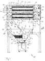
- FIG. 1 shows a filter device 10 according to the invention with one of two filter chambers arranged one above the other 14, 16 formed filter housing 12 and one below of the filter housing 12 arranged bunker 18th
- the bunker 18 is formed from two parts, namely one upper gas inlet module 21 with a substantially rectangular Cross section, the length of which is essentially the length of the filter chamber 14, 16 placed thereon, whereby the modular structure of the illustrated and described Filter device 10 is supported.
- the gas entry module 21 of the bunker 18 is arranged with one below Dust funnel 22 connected, which has a downwardly tapering, essentially funnel-shaped cross-section having.
- the training of the bunker is a matter of course 18 not on the two-part shown and described Design limited, but there are also one-piece or bunkers consisting of more than two parts possible, at least in sections to facilitate particle removal are funnel-shaped.
- the bunker 18 is provided with a gas inlet opening 20, that in the embodiment of Figure 1 on the left Front side of the gas inlet module 21 of the bunker 18 attached and through which is a particle-containing to be cleaned Gas can be supplied.
- a partition is inside the bunker 18 23 provided, extending from a filter chamber-side upper End 24 of the bunker 18 through the gas inlet module 21 and the dust hopper 22 of the bunker 18 extends downward to one at the bottom funnel end of the dust funnel 22 trained outlet opening 25.
- the partition 23 runs obliquely in an upper section 26 and in one lower section 27 substantially vertically downwards.
- the lower one, into the outlet opening 25 of the bunker 18th reaching end of the partition 23 is as freely movable Flap 28 formed on the lower edge of the vertical Section 27 of the partition 23 hinged and between a gravitational first position 28.1 (drawn in continuously) and a side wall 29 of the bunker 18 tightly acting second position 28.2 (shown in dashed lines) adjustable.
- the partition 23 is formed as a trough 30.
- the partition 23 divides the interior of the bunker 18 into one of the gas inlet opening Gas supply area 18.1 and one from the gas inlet opening 20 separated particle discharge area 18.2.
- Something in a lower section of the gas supply area 18.1 A perforated plate 32 is arranged above the outlet opening 25, that spans the entire floor plan of the gas supply area 18.1 extends at this level and essentially is roof-shaped (see also Figure 2).
- the perforated plate 32, as in the embodiment 1 is shown between a lower tear-off edge 34 of the trough 30 and the articulation axis 36 of the flap 28 is arranged.
- the one Filter housing 14 On the upper open end 24 of the bunker 18 are the one Filter housing 14 forming filter chambers 14, 16 one above the other put on.
- the two filter chambers 14, 16 are at the top and open at the bottom, with the filter chamber 16 tightly fitting lid 40 is placed.
- the filter cartridges 42 are conventional Filter cartridges that are well known in the art and on their detailed description in the context of this Registration is waived. As from the representation of the figure 1, each so-called filter cartridge 42 actually composed of two shorter partial cartridges 42.1, 42.2, which are arranged coaxially one behind the other are, being in the space between the two cartridges 42.1, 42.2 a sealing ring 43 is arranged in each case. This assembly of two or more filter cartridges for a whole cartridge is also known. Of course the invention is also for use with a filter cartridge consisting of a single cartridge.
- each filter chamber 14, 16 is longer than those used therein Filter cartridges 42, done by inserting the Filter cartridges 42 into the filter chambers 14, 16 a subdivision each filter chamber into two sections, namely one first section A, in which there is no filter material, and a second section B, in which (at inserted filter cartridge) filter material.
- Operational the filter device according to the invention has the first Section A of each filter chamber 14, 16 the function of a feed channel, while the second sections B die "Cleaning sections" are.
- the rod 50 hereinafter referred to as the tension rod is with a tension rod 50 at a first end 52 attached sliding block 54 releasably behind in one arranged the supply channel end wall of the filter chamber Groove 56 designed to be engageable.
- This front wall lies the "closable" open by the inflow nozzle 44 Side through which the filter cartridge 42 is inserted, opposite.
- the inflow nozzle 44 thus simultaneously serves as Tensioning and sealing elements for the filter cartridge 42.
- the clamping means 62 is in the embodiment of Figures 1 and 4 a coil spring 62, the by means of a nut 63 forming a stop on the Tension rod 50 set toward the first end is. That the stop formed by the lock nut 63 far end of the coil spring 62 acts on one Plate 64, which is suitable for the associated front end 45 to close the filter cartridge 42.
- a sealing ring 65 between plate 64 and filter cartridge 42 is provided.
- the plate 64 corresponds with hers Shape essentially the cross section of the filter cartridge 42.
- the plate 64 is advantageously by means of a central one Bore on the tension rod 50 positively and tightly placed and slidably arranged on it.
- the filter cartridge 42 out over the tie rod 50.
- This can either be outside the filter chamber, so that the filter cartridge and the tension rod (with the Plate 64) placed together in the filter chamber be, or the tension rod 52 with the sliding block 54, the tensioning means 62 and the plate 64 carrying end 52 first inserted into the filter chamber and with the sliding block 54 inserted behind the groove 56 provided for this purpose, whereupon the filter cartridge over the in the filter chamber located (anchored and secured against rotation) Tension rod is guided.
- the sliding block To facilitate 54 in the groove 56 this is in particular downward funnel-shaped, like this is illustrated with reference to FIG. 3.
- the sliding block 54 can be simple in the sense of the double arrow P. inserted into the groove 56 and again from this be removed.
- the groove 56 can be formed, for example, by a groove plate 58 be formed approximately in the middle of the feed channel side Front of the filter chamber is attached. A possible The design of the groove plate 58 is shown in FIG. 3.
- the opposite End of the filter cartridge 42 with a holding and Established structure which is a conventional Holding cross or in particular around the already mentioned inlet nozzle 44 can act.
- the tension rod 50 protrudes with a second opposite the first end 52 End 53 through a bore provided in the inflow nozzle 44 and is there by means of a not shown Nut set such that the inlet nozzle 44th sealingly against the end of the filter cartridge 42 and the filter cartridge 42 thereby in turn against the plate 64 and the clamping means 62 is pressed so that a holder the filter cartridge 42 in the firmly clamped state and one Division of the filter chamber into a serving as a feed channel free section A and one with the filter cartridge 42 occupied second section B with filter material for cleaning of gas containing particles.
- the tension rod is particularly simple handle. With the sliding block 54 inserted into the groove 56 the tie rod 50 is placed on the tie rod 50 slidable plate 64 on the support tubes 60th supported. Because of the much longer, to open end of the filter chamber facing free section The tension rod 50 generated leverage becomes the tension rod 50 held in the substantially horizontal position since the end 52 provided with the sliding block 54 Tension rod 50 is pressed up into the groove. Thereby the filter cartridge is particularly easy to use Push the tension rod into the interior of the filter chamber, since the tension rod does not have to be held separately.
- Perforated plate 32 is achieved on the one hand that the below the area of the perforated plate that is flow-calmed and on the other hand that coarse particles contained in the gas be separated (pre-separation) and in the sense of drawn arrows down towards the outlet opening 25 of the bunker 18 fall where they pass through the outlet opening 25 into a (mobile) dust container 70 reach.
- other discharge organs such as. Legs Cell wheel lock, a slit valve, a double pendulum flap be provided.
- the gas supplied into the gas supply area 18.1 creates a relative overpressure P 1 in the gas supply area 18.1, which causes the flap 28 articulated at the lower end of the vertical lower section 27 of the partition 23 to be pressed out of its gravitational rest position 28.1 towards the particle discharge area 18.2 or is sucked until it acts on the side wall 29 of the particle discharge area 18.2 of the bunker 18.
- the gas supplied is first down and then redirected upwards in the direction of the filter chambers.
- the gas that reached due to the perforated plate 32 Pre-separation essentially only fine dust contains, passes through the open upper end 24 of the bunker 18 through the upper inclined section 26 of the partition 23 deflected out and into the feed channel A of the arranged above Filter chambers 14, 16.
- Due to the air ducting described the arrangement occurs the gas with a very uniform speed profile in the Feed channel A of the filter chambers, where there is not least because of the turbulence imparted to the filter cartridges 42 is distracted and essentially one axial flow against the filter cartridges 42 in the filter chambers 14, 16 is achieved.
- the gas occurs in the sense of the drawn Arrows through the filter material Sheath of the filter cartridges 42 inside, where a separation and cleaning of the dust particles from the Gas occurs.
- the one inside the filter cartridges Purified air is drawn over the opposite head end of the filter cartridges and downstream of each filter chamber second chambers 15, 17 in the sense of the drawn Arrows through a gas outlet 19 to a not shown Fan extracted.
- the particle discharge area 18.2 of the dust bunker 18 connects below the cleaning areas B of the filter chambers 14, 16. A lower pressure P 2 than the pressure P 1 in the gas supply area 18.1 is formed in the particle discharge area 18.2.
- the particle removal area 18.2 is a flow-calmed zone in which, as has been proven by measurements, there is practically no gas flow in practice. For this reason, dust particles falling from the filter material of the filter cartridges 42 can fall down unhindered (due to gravity) through the particle discharge area 18.2, without being driven upwards again by a disturbing gas flow.
- the flap 28 As soon as the weight of the dust particles on the flap 28 is greater than the pressure force exerted on the flap by the overpressure P 1 , the flap 28 is pressed in the direction of its rest position 28.1 and the accumulated dust can fall through the outlet opening 25 into the associated dust container 70 .
- Another possibility of moving the flap 28 from the “closed” position 28.2 in the direction of the rest position 28.1 is to increase the pressure P 2 in the particle discharge area 18.2 above the pressure P 1 in the gas supply area 18.1.
- This is the case when compressed air is blown into the interior of the filter cartridges 42 by means of compressed air systems 72 arranged in the second chambers 15, 17 and assigned to each filter cartridge, in order to achieve a cleaning of the dust particles separated on the filter material of the filter cartridges 42.
- the dust particles are blown off the filter cartridges and due to the pressure increase, dust particles already in the particle discharge area 18.2 are also carried downwards, the flap 28 is briefly pushed open from its closed position 28.2 and accumulated dust is conveyed into the dust container 70.
- the inventive design of the bunker guide plates in Connection with the flap thus enables implementation the so-called downdraft principle in the filter room, i.e.
- the Air flow in the filter room is directed from top to bottom and thus allows the dust to be cleaned off in the dust bunker without disturbing upward flow.
Landscapes
- Chemical & Material Sciences (AREA)
- Chemical Kinetics & Catalysis (AREA)
- Filtering Of Dispersed Particles In Gases (AREA)
Applications Claiming Priority (2)
| Application Number | Priority Date | Filing Date | Title |
|---|---|---|---|
| DE19949894 | 1999-10-15 | ||
| DE19949894 | 1999-10-15 |
Publications (1)
| Publication Number | Publication Date |
|---|---|
| EP1092463A1 true EP1092463A1 (fr) | 2001-04-18 |
Family
ID=7925859
Family Applications (1)
| Application Number | Title | Priority Date | Filing Date |
|---|---|---|---|
| EP00121774A Withdrawn EP1092463A1 (fr) | 1999-10-15 | 2000-10-05 | Dispositif de filtration et dispositif pour fixer des cartouches de filtration |
Country Status (1)
| Country | Link |
|---|---|
| EP (1) | EP1092463A1 (fr) |
Cited By (8)
| Publication number | Priority date | Publication date | Assignee | Title |
|---|---|---|---|---|
| DE102016121779A1 (de) | 2016-11-14 | 2018-05-17 | Camfil Apc Gmbh | Filteranlage mit Reinigungsluftleiteinrichtung für horizontale Filterpatronen und Verfahren zum Reinigen einer Filteranlage |
| DE102016015799A1 (de) | 2016-11-14 | 2018-05-17 | Camfil Apc Gmbh | Filteranlage mit Reinigungsluftleiteinrichtung für horizontale Filterpatronen und Verfahren zum Reinigen einer Filteranlage |
| DE102016015802A1 (de) | 2016-11-14 | 2018-05-17 | Camfil Apc Gmbh | Filteranlage mit Reinigungsluftleiteinrichtung für horizontale Filterpatronen und Verfahren zum Reinigen einer Filteranlage |
| DE102016015798A1 (de) | 2016-11-14 | 2018-05-17 | Camfil Apc Gmbh | Filteranlage mit Reinigungsluftleiteinrichtung für horizontale Filterpatronen und Verfahren zum Reinigen einer Filteranlage |
| CN112915675A (zh) * | 2021-01-21 | 2021-06-08 | 南昌大学 | 一种阻碍碰撞式脉喷清灰滤筒除尘装置 |
| CN113559593A (zh) * | 2021-07-22 | 2021-10-29 | 王立章 | 一种工业酶制剂的精滤设备 |
| CN116492793A (zh) * | 2023-04-13 | 2023-07-28 | 安徽紫朔环境工程技术有限公司 | 一种工业窑炉烟气净化排放设备 |
| CN117082736A (zh) * | 2023-08-01 | 2023-11-17 | 汇通电子科技(惠州)有限公司 | 一种线路板浸泡装置及线路板加工设备 |
Citations (6)
| Publication number | Priority date | Publication date | Assignee | Title |
|---|---|---|---|---|
| FR908630A (fr) * | 1944-08-01 | 1946-04-15 | Sev Marchal | Perfectionnement aux appareils d'épuration des gaz à compartiments de filtration juxtaposés débouchant chacun par une ouverture obturable dans un collecteur commun de sortie des gaz épurés |
| CH338081A (fr) * | 1955-12-01 | 1959-04-30 | Morristown Trust Company | Filtre |
| CH640425A5 (en) * | 1979-05-04 | 1984-01-13 | Boris Borisovich Kudryavtsev | Cartridge filter |
| EP0314253A1 (fr) * | 1987-10-30 | 1989-05-03 | Shell Internationale Researchmaatschappij B.V. | Procédé et dispositif de séparation de particules fines dans un mélange de particules fines et d'un gaz |
| WO1991003689A1 (fr) * | 1989-09-06 | 1991-03-21 | Airchitect I Söderhamn Ab | Unite de filtrage destinee a nettoyer de l'air d'alimentation |
| DE4405597C1 (de) * | 1994-02-22 | 1996-01-04 | Sult Gmbh Staub Und Lufttechni | Filtervorrichtung für mit Partikeln verunreinigtes Gas |
-
2000
- 2000-10-05 EP EP00121774A patent/EP1092463A1/fr not_active Withdrawn
Patent Citations (6)
| Publication number | Priority date | Publication date | Assignee | Title |
|---|---|---|---|---|
| FR908630A (fr) * | 1944-08-01 | 1946-04-15 | Sev Marchal | Perfectionnement aux appareils d'épuration des gaz à compartiments de filtration juxtaposés débouchant chacun par une ouverture obturable dans un collecteur commun de sortie des gaz épurés |
| CH338081A (fr) * | 1955-12-01 | 1959-04-30 | Morristown Trust Company | Filtre |
| CH640425A5 (en) * | 1979-05-04 | 1984-01-13 | Boris Borisovich Kudryavtsev | Cartridge filter |
| EP0314253A1 (fr) * | 1987-10-30 | 1989-05-03 | Shell Internationale Researchmaatschappij B.V. | Procédé et dispositif de séparation de particules fines dans un mélange de particules fines et d'un gaz |
| WO1991003689A1 (fr) * | 1989-09-06 | 1991-03-21 | Airchitect I Söderhamn Ab | Unite de filtrage destinee a nettoyer de l'air d'alimentation |
| DE4405597C1 (de) * | 1994-02-22 | 1996-01-04 | Sult Gmbh Staub Und Lufttechni | Filtervorrichtung für mit Partikeln verunreinigtes Gas |
Cited By (11)
| Publication number | Priority date | Publication date | Assignee | Title |
|---|---|---|---|---|
| DE102016121779A1 (de) | 2016-11-14 | 2018-05-17 | Camfil Apc Gmbh | Filteranlage mit Reinigungsluftleiteinrichtung für horizontale Filterpatronen und Verfahren zum Reinigen einer Filteranlage |
| DE102016015799A1 (de) | 2016-11-14 | 2018-05-17 | Camfil Apc Gmbh | Filteranlage mit Reinigungsluftleiteinrichtung für horizontale Filterpatronen und Verfahren zum Reinigen einer Filteranlage |
| DE102016015802A1 (de) | 2016-11-14 | 2018-05-17 | Camfil Apc Gmbh | Filteranlage mit Reinigungsluftleiteinrichtung für horizontale Filterpatronen und Verfahren zum Reinigen einer Filteranlage |
| DE102016015798A1 (de) | 2016-11-14 | 2018-05-17 | Camfil Apc Gmbh | Filteranlage mit Reinigungsluftleiteinrichtung für horizontale Filterpatronen und Verfahren zum Reinigen einer Filteranlage |
| CN112915675A (zh) * | 2021-01-21 | 2021-06-08 | 南昌大学 | 一种阻碍碰撞式脉喷清灰滤筒除尘装置 |
| CN112915675B (zh) * | 2021-01-21 | 2024-05-07 | 南昌大学 | 一种阻碍碰撞式脉喷清灰滤筒除尘装置 |
| CN113559593A (zh) * | 2021-07-22 | 2021-10-29 | 王立章 | 一种工业酶制剂的精滤设备 |
| CN113559593B (zh) * | 2021-07-22 | 2022-08-30 | 天大北洋(天津)科技有限公司 | 一种工业酶制剂的精滤设备 |
| CN116492793A (zh) * | 2023-04-13 | 2023-07-28 | 安徽紫朔环境工程技术有限公司 | 一种工业窑炉烟气净化排放设备 |
| CN117082736A (zh) * | 2023-08-01 | 2023-11-17 | 汇通电子科技(惠州)有限公司 | 一种线路板浸泡装置及线路板加工设备 |
| CN117082736B (zh) * | 2023-08-01 | 2024-04-05 | 汇通电子科技(惠州)有限公司 | 一种线路板浸泡装置及线路板加工设备 |
Similar Documents
| Publication | Publication Date | Title |
|---|---|---|
| DE2104758A1 (de) | Verfahren zum Reinigen von durchlässigen Filtern und Vorrichtung zum Durchführen des Verfahrens | |
| DE3109154C2 (de) | Vorrichtung zum Abscheiden von Fremdkörpern, insbesondere Schwerteilen wie Metall-, Holz- und Pappteilen o.dgl. aus Baumwollfaserflocken | |
| EP1034023A1 (fr) | Procede pour nettoyer des bougies d'un filtre a bougies | |
| DE2103332A1 (de) | Trocknungsvorrichtung | |
| DE1274560B (de) | Vorrichtung zum Entstauben von Industriegasen | |
| DE3933405A1 (de) | Durchlauf-vakuum-auftragsvorrichtung | |
| DE2451927C3 (de) | Offen-End-Spinnvorrichtung | |
| DE2065715B2 (de) | Vorrichtung zum Entfernen von Filterriickständen bei schlauch- oder beuteiförmigen Filtern mittels Druckgasstößen im Rückspülverfahren | |
| DE4134679C2 (de) | Feinstaubfilter | |
| DE3930765C1 (en) | Tubular gas filter - has several chambers contg. filter elements in housing, with dust collection bunker under each chamber | |
| DE1036133B (de) | Vorrichtung zum Beseitigen von Faserflug u. dgl. bei Spinnereimaschinen und Zwirnmaschinen mittels Blasluft | |
| DE4218318C2 (de) | Reinigungseinrichtung für Luftdruckfühler an Windsichtern | |
| AT506149A1 (de) | Fördervorrichtung für kleinteile | |
| EP0270012B1 (fr) | Procédé et dispositif pour amener du matériel en vrac à travers un sas | |
| DE4212269C2 (fr) | ||
| AT409225B (de) | Axial-hohlkegeldüse zum versprühen flüssiger medien | |
| DE3932156C2 (de) | Filteranlage | |
| DE4405597C1 (de) | Filtervorrichtung für mit Partikeln verunreinigtes Gas | |
| DE2655275A1 (de) | Staubgasfilter mit filterschlaeuchen oder filtertaschen | |
| DE666452C (de) | Spritzvorrichtung fuer schmelzbares, pulverfoermiges Spritzgut | |
| DE2029728A1 (de) | Verfahren und Vorrichtung zum Staubentfernen von Filterflächen | |
| DE2608721C2 (de) | Anlage zur Trennung eines Gemisches aus Schrott und Schutt | |
| DE2364458B2 (de) | Verfahren und vorrichtung zum betrieb einer planiervorrichtung | |
| DE3443182C2 (fr) | ||
| DE2031011A1 (en) | Cleaning dust separation filters |
Legal Events
| Date | Code | Title | Description |
|---|---|---|---|
| PUAI | Public reference made under article 153(3) epc to a published international application that has entered the european phase |
Free format text: ORIGINAL CODE: 0009012 |
|
| AK | Designated contracting states |
Kind code of ref document: A1 Designated state(s): AT BE CH CY DE DK ES FI FR GB GR IE IT LI LU MC NL PT SE |
|
| AX | Request for extension of the european patent |
Free format text: AL;LT;LV;MK;RO;SI |
|
| AKX | Designation fees paid | ||
| REG | Reference to a national code |
Ref country code: DE Ref legal event code: 8566 |
|
| STAA | Information on the status of an ep patent application or granted ep patent |
Free format text: STATUS: THE APPLICATION IS DEEMED TO BE WITHDRAWN |
|
| 18D | Application deemed to be withdrawn |
Effective date: 20011019 |