EP1092476B1 - Broyeur déchiqueteur - Google Patents
Broyeur déchiqueteur Download PDFInfo
- Publication number
- EP1092476B1 EP1092476B1 EP20000122110 EP00122110A EP1092476B1 EP 1092476 B1 EP1092476 B1 EP 1092476B1 EP 20000122110 EP20000122110 EP 20000122110 EP 00122110 A EP00122110 A EP 00122110A EP 1092476 B1 EP1092476 B1 EP 1092476B1
- Authority
- EP
- European Patent Office
- Prior art keywords
- stator
- cutting
- rotor
- cutting element
- circumference
- Prior art date
- Legal status (The legal status is an assumption and is not a legal conclusion. Google has not performed a legal analysis and makes no representation as to the accuracy of the status listed.)
- Expired - Lifetime
Links
- 239000000463 material Substances 0.000 claims description 10
- 239000004033 plastic Substances 0.000 claims description 8
- 229920003023 plastic Polymers 0.000 claims description 8
- 238000002347 injection Methods 0.000 claims description 2
- 239000007924 injection Substances 0.000 claims description 2
- 230000004308 accommodation Effects 0.000 claims 1
- 238000010438 heat treatment Methods 0.000 claims 1
- 239000000428 dust Substances 0.000 description 6
- 239000008187 granular material Substances 0.000 description 2
- 238000004519 manufacturing process Methods 0.000 description 2
- 208000015943 Coeliac disease Diseases 0.000 description 1
- 238000013459 approach Methods 0.000 description 1
- 230000015572 biosynthetic process Effects 0.000 description 1
- 239000000969 carrier Substances 0.000 description 1
- 230000000295 complement effect Effects 0.000 description 1
- 238000010276 construction Methods 0.000 description 1
- 230000000694 effects Effects 0.000 description 1
- 230000002349 favourable effect Effects 0.000 description 1
- 239000002440 industrial waste Substances 0.000 description 1
- 238000001746 injection moulding Methods 0.000 description 1
- 238000000034 method Methods 0.000 description 1
- 230000036346 tooth eruption Effects 0.000 description 1
Images



Classifications
-
- B—PERFORMING OPERATIONS; TRANSPORTING
- B29—WORKING OF PLASTICS; WORKING OF SUBSTANCES IN A PLASTIC STATE IN GENERAL
- B29B—PREPARATION OR PRETREATMENT OF THE MATERIAL TO BE SHAPED; MAKING GRANULES OR PREFORMS; RECOVERY OF PLASTICS OR OTHER CONSTITUENTS OF WASTE MATERIAL CONTAINING PLASTICS
- B29B17/00—Recovery of plastics or other constituents of waste material containing plastics
- B29B17/04—Disintegrating plastics, e.g. by milling
-
- B—PERFORMING OPERATIONS; TRANSPORTING
- B02—CRUSHING, PULVERISING, OR DISINTEGRATING; PREPARATORY TREATMENT OF GRAIN FOR MILLING
- B02C—CRUSHING, PULVERISING, OR DISINTEGRATING IN GENERAL; MILLING GRAIN
- B02C18/00—Disintegrating by knives or other cutting or tearing members which chop material into fragments
- B02C18/06—Disintegrating by knives or other cutting or tearing members which chop material into fragments with rotating knives
- B02C18/08—Disintegrating by knives or other cutting or tearing members which chop material into fragments with rotating knives within vertical containers
-
- B—PERFORMING OPERATIONS; TRANSPORTING
- B02—CRUSHING, PULVERISING, OR DISINTEGRATING; PREPARATORY TREATMENT OF GRAIN FOR MILLING
- B02C—CRUSHING, PULVERISING, OR DISINTEGRATING IN GENERAL; MILLING GRAIN
- B02C18/00—Disintegrating by knives or other cutting or tearing members which chop material into fragments
- B02C18/06—Disintegrating by knives or other cutting or tearing members which chop material into fragments with rotating knives
- B02C18/08—Disintegrating by knives or other cutting or tearing members which chop material into fragments with rotating knives within vertical containers
- B02C18/086—Disintegrating by knives or other cutting or tearing members which chop material into fragments with rotating knives within vertical containers specially adapted for disintegrating plastics, e.g. cinematographic films
-
- B—PERFORMING OPERATIONS; TRANSPORTING
- B02—CRUSHING, PULVERISING, OR DISINTEGRATING; PREPARATORY TREATMENT OF GRAIN FOR MILLING
- B02C—CRUSHING, PULVERISING, OR DISINTEGRATING IN GENERAL; MILLING GRAIN
- B02C18/00—Disintegrating by knives or other cutting or tearing members which chop material into fragments
- B02C18/06—Disintegrating by knives or other cutting or tearing members which chop material into fragments with rotating knives
- B02C18/16—Details
- B02C18/18—Knives; Mountings thereof
-
- Y—GENERAL TAGGING OF NEW TECHNOLOGICAL DEVELOPMENTS; GENERAL TAGGING OF CROSS-SECTIONAL TECHNOLOGIES SPANNING OVER SEVERAL SECTIONS OF THE IPC; TECHNICAL SUBJECTS COVERED BY FORMER USPC CROSS-REFERENCE ART COLLECTIONS [XRACs] AND DIGESTS
- Y02—TECHNOLOGIES OR APPLICATIONS FOR MITIGATION OR ADAPTATION AGAINST CLIMATE CHANGE
- Y02W—CLIMATE CHANGE MITIGATION TECHNOLOGIES RELATED TO WASTEWATER TREATMENT OR WASTE MANAGEMENT
- Y02W30/00—Technologies for solid waste management
- Y02W30/50—Reuse, recycling or recovery technologies
- Y02W30/62—Plastics recycling; Rubber recycling
Definitions
- the invention relates to a cutting mill according to the preamble of claim 1.
- Such granulators are for example from the GB 2 268 097 . DE-A1-3 201 096 . DE-A1-3 444 933 and DE-U1-9 200 997 known.
- the known granulators have either an operating position in which the stator axis is horizontal and the ground material is fed radially, or an operating position in which the stator axis is vertical and the ground material is fed axially from above.
- the known granulators are usually provided with a special Vorschneidschsch and are of elongated design. If these cutting mills are used for crushing the sprues of plastic injection molded parts, it is important to gain as dust-free as possible granules that can be reused for the feeding of plastic injection molding machines.
- a granulator for industrial waste in which in a hopper housing a driven, rotating, elliptical plate is inclined to the horizontal. This plate may have cutting teeth on its outer edge, and the funnel may be eccentric.
- a granulator for fine grinding of rubber in which a rotatable in a cylinder housing rotor is formed in section egg-shaped.
- the gap between the rotor tip and cylinder housing is different in size.
- a kind of adjustable eccentric operation is used.
- the object of the invention is to provide a granulator referred to in the preamble of claim 1, which does not require special Vorschneidsch, has a short design and allows the crushing of the ground material to a low-dust granules.
- the rotor cutting element can perform a quick movement with little force on the middle of the stator to break the material to be ground in rough pieces, here is the coarse crushing in that chamber in which act the Statorschneidieri, in this chamber can remain a very large area, the can also accommodate very bulky grinding stock. As a result, a relatively small cutting mill can be built even for large grinding stock. In the area where the rotor cutting element approaches a Statorschneidelement, is due to the leverage a large force to disposal. In such areas, the main cutting work, in which the ground material is cut until it is removed, for example, a low-dust sieve the stator chamber.
- the cutting elements are simple in design, straight and can be easily replaced.
- the coarse crushing of the millbase is even more effective.
- the number of Statorschneidieri is eight and the ratio of the Statorinnenivis to the rotor circumference is selected such that the order 1, 6, 3, 8, 5, 2, 7, 4 is. Since the rotor cutting element is thereby guided through the stator chamber center after each fine cut, the coarse shredding is further improved.
- the rotor circumference rolls on the stator inner circumference.
- the rotor may be provided with an external toothing and the stator with an internal toothing.
- stator cutting elements and the number of rotor cutting elements can be chosen arbitrarily.
- a granulator in which according to a further embodiment of the invention, three Statorschneidieri and three rotors are provided, has proved to be particularly simple and effective.
- the ratio of the Statorinnenivis chosen to the rotor circumference such that the rotor cutting element of each rotor per rotor circulation cooperates with the next stator cutting element.
- a further embodiment of the invention relates to a cutting mill having an operating position with a vertical stator axis and in which the plastic parts are fed axially from above.
- This design is such that the stator has an inner chamber which is bounded by a number of Statorschneidieri corresponding number of webs whose narrow sides each have a certain distance to narrow sides of the adjacent webs, and that each Statorschneidelement on an associated, frame-shaped Cutting element carrier is attached, which has two arranged on both sides of the Statorschneidelements pockets for receiving the web ends of two adjacent webs.
- the cutting element carriers are formed quadrangular, wherein at one corner the stator cutting element is arranged and the pockets are arranged in the vicinity of the Statorschneidelements.
- An advantageous, further embodiment of the invention provides that above the Statorschneidiata a horizontal cutting ring is arranged, whose inner circumference substantially corresponds to the Statorinnenide, and that a horizontal rotor blade is arranged on the rotor, which cooperates with the cutting ring.
- a horizontal rotor blade is arranged on the rotor, which cooperates with the cutting ring.
- the coarse shredding is further improved.
- this "caps" long plastic parts is possible.
- This additional, horizontal cutting device of cutting ring and horizontal rotor cutting cuts the material to be ground with the same, favorable, aforementioned Leverage such that it can be immediately further crushed between the vertical cutting elements.
- the horizontal rotor blade is disc-shaped.
- the horizontal cutting and the vertical cutting elements are characterized by the fact that they taper towards each other. This reduces the breakage area when separating and increases the area that is cut. As a result, the dust content is kept low during the crushing process.
- the Statorinnenhunt can additionally be heated to increase the plastic behavior of the plastics and thus reduce the dust content again and reduce cutting edge wear.
- a support for the rotor cutting element is provided, which is designed as the carrier of the Statorschneidelements. This results in a manufacturing advantage in the production of the cutting element carrier.
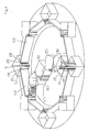
- Fig. 1 sketched granulator has eight Statorschneidieri 1-8, which are each attached to the associated Statorscheidelement istn 1.1-8.1 easily replaceable.
- the Statorschneidelement situated 1.1-8.1 are arranged evenly distributed on the inner circumference 9 of a stator 10.
- the vertical axis of the stator in the operating position of the cutting mill is denoted by 11.
- the inner chamber of the stator 10 is one of the number of Statorschneidieri 1-8 corresponding number of webs 1.2-8.2 limited, which are part of the stator 10 and whose narrow sides each have a certain distance a to narrow sides of the adjacent webs.
- the Statorschneidelement situated 1.1-8.1 are attached to the webs 1.2-8.2. The nature of this attachment and this carrier will be explained later in more detail.
- a rotor 12 with a circumference 13 is arranged eccentrically.
- the axis of the rotor 12 is denoted by 14.
- the circumference 13 is substantially smaller than the stator inner periphery 9.
- a rotor cutting element carrier 15 is arranged, on which a with the Statorschneidierin 1-8 cooperating rotor cutting element 16 is fixed, which lies on the circumference 13.
- the rotor 12 rolls with its circumference 13 on the inner circumference 9 of the stator 10.
- the rotor axis 14 is guided on a circular path 17 about the stator 11. How the leadership of the rotor 12 is done, has not been shown in detail.
- the guide can be effected by means of a lever which is driven in the stator axis 11 and to which the rotor 12 is rotatably fastened, while an external toothing of the rotor and an internal toothing of the stator bring the rotor 12 into engagement with the stator 10.
- Fig. 1 the ratio of the Statorinnen representatives 9 to the rotor circumference 13 is selected such that the rotor cutting element 16 per rotor circulation with one of the next Statorschneidelement 2 opposite Statorschneidelement cooperates, with all Statorschneidieri 1-8 involved in a particular order.
- the rotor 12 rolls past the Statorschneidierin 2-5 before the rotor cutting element 16 strikes the stator cutting element 6 after a rotor rotation.
- the rotor cutting element 16 is opened meet the stator cutting element 3, etc., so that the particular order to 1, 6, 3, 8, 5, 2, 7, 4 results, after which then the starting position of Fig. 2A is reached.
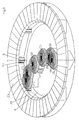
- Fig. 3 is the path of the rotor cutting element 16 and the rotor cutting element carrier 15 in the valid for a rotor circulation phases of Fig. 2 shown, wherein the rotor itself has been omitted for clarity. Accordingly, the rotor cutting element 16 runs essentially through the center of the stator inner chamber and breaks up a grinding material part 18 in the region X before it cuts pieces of the grinding material in the region Y. Coarse comminution thus takes place in region X, while fine comminution takes place in region Y. The latter happens without generation of significant dust content.
- Fig. 4 is a perspective view of the cutting mill of Fig. 1 shown, wherein the Fig. 4 in the Figures 2 . 3 represented phases AF also reproduces. Since the construction of the Statorschneidelement regarding 1.1-8.1 and the Statorschneidieri 1-8 is the same and the attachment of Statorschneidelementpertaining to the webs 1.2-8.2 is always the same, an exemplary description of a Statorschneidelemtmays, here the carrier 5.1, and its attachment to the associated pair of webs is sufficient , here the bars 4.2 and 5.2.
- the Statorschneidelement here 5.1 consists of a square frame. At a corner of the frame, the stator cutting element 5 is fixed, which has a straight, vertical cutting edge. On both sides and in the vicinity of the stator cutting element 5, the stator cutting element carrier 5.1 has two vertical pockets 19, 20, received in the ends 21, 22 of the webs 4.2 and 5.2 are. To replace the Statorschneidelement concerneds 5.2 this is simply pulled upwards, and a new carrier is pushed from above onto the web ends 21, 22. From the Fig. 4 It can also be seen that a carrier 15 is provided for the rotor cutting element 16, which is designed like the carrier 5.1 of the stator cutting element 5.
- a horizontal cutting device is provided, which is formed from a cutting ring 23 and a horizontal rotor cutting edge 24.
- the cutting ring 23 has an inner circumference 25, which substantially corresponds to the Statorinnencum 9 is disposed above the Statorschneidieri 1-8 and covers the Statorschneidelement ist 1.2-8.2 from.
- the horizontal rotor blade 24 is disc-shaped, covers the rotor cutting element carrier 15 and cooperates with the cutting ring 23, as seen from Fig. 5 evident.
- FIG. 6 Another embodiment of the additional horizontal cutting device is in Fig. 6 shown.
- this cutting device consists of plates, such as the plate 26, each covering the Statorschneidelement notion terme 1.1-8.1, and a plate 27, which covers the rotor cutting element carrier 15.
- the plates 26, 27 are provided with sickle-shaped cutting edges 28, 29, which are complementary to each other.
- Fig. 7 the effect of this additional cutting device is shown.
- a long leg of Mahlgutteils 18 is cut off, after which the abraded Mahlgutteil can be cut with the vertical cutting elements.
- each rotor 12.1-12.3 is significantly smaller than that of the rotor 12 and so selected with respect to the stator inner circumference that the rotor cutting element 16.1-16.3 of each rotor 12.1-12.3 per rotor revolution cooperates with the next stator cutting element 2 ', 3', 1 ' it from the Figures 8B-8D evident. Even with this simple design of the granulator, a dust-free regrind comminution in the range X ( Fig. 8B ) and grinding fine comminution in the range Y ( Fig. 8D ) reached. In order to minimize dust formation, it is advantageous if the cutting room z. B. is heated by means of radiators.
Landscapes
- Engineering & Computer Science (AREA)
- Food Science & Technology (AREA)
- Environmental & Geological Engineering (AREA)
- Mechanical Engineering (AREA)
- Crushing And Pulverization Processes (AREA)
- Glass Compositions (AREA)
- Saccharide Compounds (AREA)
- Processing And Handling Of Plastics And Other Materials For Molding In General (AREA)
- Milling Processes (AREA)
Claims (12)
- Broyeur déchiqueteur pour fragmenter des pièces en matière plastique, notamment des carottes de pièces moulées par injection, comprenant un stator sur le pourtour intérieur duquel sont répartis uniformément des éléments statoriques de déchiquetage et un rotor qui tourne dans le stator et sur la périphérie duquel est monté au moins un élément rotorique de déchiquetage, les éléments statoriques de déchiquetage coopérant avec l'élément rotorique de déchiquetage, dans lequel au moins un rotor (12) est monté de manière excentrée dans le stator (10), a une périphérie (13) sensiblement plus petite que la périphérie (9) intérieure du stator et se déplace par son axe (14) sur une trajectoire (17) circulaire autour de l'axe (11) du stator,
caractérisé en ce que
le nombre des éléments (1 à 8) statoriques de déchiquetage et le rapport de la périphérie (9) intérieure du stator à la périphérie (13) du rotor sont choisis de façon à ce que l'élément (16) rotorique de déchiquetage coopère à chaque tour du rotor avec l'un (5) des éléments (3 à 8) statoriques de déchiquetage opposés à l'élément (2) statorique de déchiquetage immédiatement suivant, tous les éléments (1 à 8) statoriques de déchiquetage faisant partie d'une succession déterminée. - Broyeur déchiqueteur suivant la revendication 1,
caractérisé en ce que
la périphérie (13) du rotor roule sur la périphérie (9) intérieure du stator. - Broyeur déchiqueteur suivant la revendication 2,
caractérisé en ce que
le rotor (12) est muni d'une denture extérieure et le stator (10) d'une denture intérieure. - Broyeur déchiqueteur suivant la revendication 3,
caractérisé en ce que
le nombre des éléments (1 à 8) de déchiquetage est de huit et le rapport de la périphérie (9) intérieure du stator à la périphérie (13) du rotor est choisi de façon à ce que la succession soit de 1, 6, 3, 8, 5, 2, 7, 4. - Broyeur déchiqueteur suivant l'une des revendications 1 à 3,
caractérisé en ce qu'il est prévu trois éléments (1' à 3') statoriques de déchiquetage et trois rotors (12.1 à 12.3). - Broyeur déchiqueteur suivant la revendication 5,
caractérisé en ce que
le rapport de la périphérie intérieure du stator à la périphérie de rotor est choisi de façon à ce que l'élément (16.1 à 16.3) rotorique de déchiquetage de chaque rotor (12.1 à 12.3) coopère à chaque tour du rotor avec l'élément (2', 3', 1') statorique de déchiquetage immédiatement suivant. - Broyeur déchiqueteur suivant l'une des revendications 1 à 6, qui a une position de fonctionnement ayant un axe de stator vertical et dans lequel les pièces en matières plastiques sont apportés axialement par le haut,
caractérisé
en ce que le stator (10) a une chambre intérieure qui est délimitée par un nombre de barrettes (1.2 à 8.2) correspondant au nombre des éléments (1 à 8) statoriques de déchiquetage et dont les petits côtés sont respectivement à une distance (a) déterminée des petits côtés des barrettes voisines et en ce chaque élément statorique de déchiquetage est fixé à un support (par exemple : 5.1) d'élément statorique de déchiquetage en forme de cadre qui lui est associé et qui a deux poches (19, 20) disposées des deux côtés de l'élément statorique de déchiquetage pour la réception des extrémités (21, 22) de deux barrettes (4.1 et 5.1) voisines. - Broyeur déchiqueteur suivant la revendication 7,
caractérisé en ce que
le support (par exemple 5.1 d'élément de déchiquetage est polygonal et a, à un sommet, l'élément (5) statorique de déchiquetage et en ce que les poches (19, 20) sont disposés à proximité de l'élément (5) statorique de déchiquetage. - Broyeur déchiqueteur suivant la revendication 7 ou 8,
caractérisé en ce qu'au dessus des éléments (1 à 8) statorique de déchiquetage est disposé un anneau (23) horizontal de déchiquetage, dont la périphérie (25) intérieure correspond sensiblement à la périphérie (9) intérieure du stator et en ce qu'il est monté sur le stator (12) un déchiqueteur (24) rotorique horizontal qui coopère avec l'anneau (23) de déchiquetage. - Broyeur déchiqueteur suivant la revendication 9,
caractérisé en ce que
le déchiqueteur (24) rotorique horizontal est en forme de disque. - Broyeur déchiqueteur suivant l'une des revendications 7 à 10,
caractérisé en ce qu'il est prévu un support (15) pour l'élément (16) rotorique de déchiquetage, qui est constitué comme le support (15.1) de l'élément (5) statorique de déchiquetage. - Broyeur déchiqueteur suivant l'une des revendications 1 à 11,
caractérisé en ce qu'il est prévu des moyens pour réchauffer l'espace de déchiquetage.
Applications Claiming Priority (2)
| Application Number | Priority Date | Filing Date | Title |
|---|---|---|---|
| DE19949706 | 1999-10-15 | ||
| DE1999149706 DE19949706A1 (de) | 1999-10-15 | 1999-10-15 | Schneidmühle |
Publications (2)
| Publication Number | Publication Date |
|---|---|
| EP1092476A1 EP1092476A1 (fr) | 2001-04-18 |
| EP1092476B1 true EP1092476B1 (fr) | 2008-05-21 |
Family
ID=7925740
Family Applications (1)
| Application Number | Title | Priority Date | Filing Date |
|---|---|---|---|
| EP20000122110 Expired - Lifetime EP1092476B1 (fr) | 1999-10-15 | 2000-10-12 | Broyeur déchiqueteur |
Country Status (3)
| Country | Link |
|---|---|
| EP (1) | EP1092476B1 (fr) |
| AT (1) | ATE395976T1 (fr) |
| DE (2) | DE19949706A1 (fr) |
Family Cites Families (8)
| Publication number | Priority date | Publication date | Assignee | Title |
|---|---|---|---|---|
| GB1424768A (en) * | 1972-08-14 | 1976-02-11 | Kobe Steel Ltd | Process and an apparatus for pulverizing materials |
| DE3201096C2 (de) | 1982-01-15 | 1987-01-15 | Colortronic Reinhard & Co Kg, 6382 Friedrichsdorf | Schneidmühle zum Zerkleinern von Angüssen |
| DE3444933A1 (de) | 1984-12-08 | 1986-06-12 | Herbold GmbH, Maschinenfabrik, 6922 Meckesheim | Schneidmuehle |
| DE8716200U1 (de) * | 1987-04-01 | 1988-07-28 | Rößler, Kurt, 4550 Bramsche | Zerkleinerungsvorrichtung |
| DE9200997U1 (de) * | 1992-01-29 | 1992-04-09 | F. Kurt Retsch GmbH & Co KG, 5657 Haan | Rotoranordnung für eine Schneidmühle |
| GB2268097B (en) * | 1992-06-19 | 1995-04-26 | Yang Mu Tsang | Crushing machine |
| SE507173C2 (sv) * | 1996-04-15 | 1998-04-20 | Kent Vedefors | Anordning för att sönderdela gods, företrädesvis från växt- eller djurriket |
| AU740821B2 (en) * | 1998-02-27 | 2001-11-15 | Maguire Products, Inc. | Radial granulator and method |
-
1999
- 1999-10-15 DE DE1999149706 patent/DE19949706A1/de not_active Withdrawn
-
2000
- 2000-10-12 DE DE50015168T patent/DE50015168D1/de not_active Expired - Fee Related
- 2000-10-12 EP EP20000122110 patent/EP1092476B1/fr not_active Expired - Lifetime
- 2000-10-12 AT AT00122110T patent/ATE395976T1/de not_active IP Right Cessation
Also Published As
| Publication number | Publication date |
|---|---|
| DE19949706A1 (de) | 2001-04-19 |
| ATE395976T1 (de) | 2008-06-15 |
| DE50015168D1 (de) | 2008-07-03 |
| EP1092476A1 (fr) | 2001-04-18 |
Similar Documents
| Publication | Publication Date | Title |
|---|---|---|
| EP0064596B1 (fr) | Broyeur granulateur pour le broyage de carottes, de pièces moulées par injection, de corps creux soufflés, etc. | |
| EP2987557B1 (fr) | Machine de broyage d'un produit | |
| EP0346661A2 (fr) | Appareil hacheur découpeur | |
| EP0090248B1 (fr) | Dispositif de déchiquetage de documents | |
| DE1757161B1 (de) | Prallmuehle | |
| EP0124138B1 (fr) | Méthode et dispositif pour le broyage de produits végétaux | |
| DE4021058C2 (fr) | ||
| DE4239342A1 (de) | Zerkleinerungsmaschine zum Mahlen oder Häckseln von industriellen und landwirtschaftlichen Produkten und Abfällen | |
| DE2502665A1 (de) | Abfallzerkleinerungsvorrichtung | |
| DE3201096C2 (de) | Schneidmühle zum Zerkleinern von Angüssen | |
| DE3313517A1 (de) | Granulator | |
| DE4342647C2 (de) | Zerkleinerungsvorrichtung | |
| DE3908395C2 (de) | Vorrichtung zum Zerkleinern von Rest- und Abfallhölzern | |
| DD256041A3 (de) | Zerkleinerungsmaschine fuer thermoplastabfaelle | |
| DE4213608A1 (de) | Verfahren und vorrichtung zum zerkleinern von gummibrocken | |
| EP1092476A1 (fr) | Broyeur déchiqueteur | |
| DE10113953C1 (de) | Vorrichtung zum Zerkleinern von Kunststoffgebilden mit geringer Materialstärke | |
| DE19606746C1 (de) | Trichterhacker zum Zerkleinern von insbesondere Holz | |
| EP2548648B1 (fr) | Broyeur pour le broyage de matière | |
| EP0302131B1 (fr) | Broyeur | |
| EP0884105A1 (fr) | Dispositif d'alimentation, de support, de palier et de montage pour appareils de broyage | |
| EP0420000B1 (fr) | Outil de coupe pour machine à broyer | |
| EP0418856B1 (fr) | Dispositif de broyage | |
| DE3104586A1 (de) | Vorrichtung zum zerkleinern von abfall | |
| DE19752803C1 (de) | Schneidwerk für eine Holzzerkleinerungsmaschine |
Legal Events
| Date | Code | Title | Description |
|---|---|---|---|
| PUAI | Public reference made under article 153(3) epc to a published international application that has entered the european phase |
Free format text: ORIGINAL CODE: 0009012 |
|
| AK | Designated contracting states |
Kind code of ref document: A1 Designated state(s): AT BE CH CY DE DK ES FI FR GB GR IE IT LI LU MC NL PT SE |
|
| AX | Request for extension of the european patent |
Free format text: AL;LT;LV;MK;RO;SI |
|
| 17P | Request for examination filed |
Effective date: 20011018 |
|
| AKX | Designation fees paid |
Free format text: AT BE CH CY DE DK ES FI FR GB GR IE IT LI LU MC NL PT SE |
|
| 17Q | First examination report despatched |
Effective date: 20061222 |
|
| GRAP | Despatch of communication of intention to grant a patent |
Free format text: ORIGINAL CODE: EPIDOSNIGR1 |
|
| RIC1 | Information provided on ipc code assigned before grant |
Ipc: B02C 18/08 20060101ALI20071203BHEP Ipc: B02C 18/00 20060101AFI20071203BHEP Ipc: B29B 17/00 20060101ALI20071203BHEP |
|
| GRAS | Grant fee paid |
Free format text: ORIGINAL CODE: EPIDOSNIGR3 |
|
| GRAA | (expected) grant |
Free format text: ORIGINAL CODE: 0009210 |
|
| AK | Designated contracting states |
Kind code of ref document: B1 Designated state(s): AT BE CH CY DE DK ES FI FR GB GR IE IT LI LU MC NL PT SE |
|
| REG | Reference to a national code |
Ref country code: GB Ref legal event code: FG4D Free format text: NOT ENGLISH |
|
| REG | Reference to a national code |
Ref country code: CH Ref legal event code: EP |
|
| REF | Corresponds to: |
Ref document number: 50015168 Country of ref document: DE Date of ref document: 20080703 Kind code of ref document: P |
|
| REG | Reference to a national code |
Ref country code: IE Ref legal event code: FG4D Free format text: LANGUAGE OF EP DOCUMENT: GERMAN |
|
| PG25 | Lapsed in a contracting state [announced via postgrant information from national office to epo] |
Ref country code: ES Free format text: LAPSE BECAUSE OF FAILURE TO SUBMIT A TRANSLATION OF THE DESCRIPTION OR TO PAY THE FEE WITHIN THE PRESCRIBED TIME-LIMIT Effective date: 20080901 Ref country code: FI Free format text: LAPSE BECAUSE OF FAILURE TO SUBMIT A TRANSLATION OF THE DESCRIPTION OR TO PAY THE FEE WITHIN THE PRESCRIBED TIME-LIMIT Effective date: 20080521 |
|
| NLV1 | Nl: lapsed or annulled due to failure to fulfill the requirements of art. 29p and 29m of the patents act | ||
| PG25 | Lapsed in a contracting state [announced via postgrant information from national office to epo] |
Ref country code: NL Free format text: LAPSE BECAUSE OF FAILURE TO SUBMIT A TRANSLATION OF THE DESCRIPTION OR TO PAY THE FEE WITHIN THE PRESCRIBED TIME-LIMIT Effective date: 20080521 |
|
| REG | Reference to a national code |
Ref country code: IE Ref legal event code: FD4D |
|
| PG25 | Lapsed in a contracting state [announced via postgrant information from national office to epo] |
Ref country code: PT Free format text: LAPSE BECAUSE OF FAILURE TO SUBMIT A TRANSLATION OF THE DESCRIPTION OR TO PAY THE FEE WITHIN THE PRESCRIBED TIME-LIMIT Effective date: 20081021 Ref country code: IE Free format text: LAPSE BECAUSE OF FAILURE TO SUBMIT A TRANSLATION OF THE DESCRIPTION OR TO PAY THE FEE WITHIN THE PRESCRIBED TIME-LIMIT Effective date: 20080521 Ref country code: DK Free format text: LAPSE BECAUSE OF FAILURE TO SUBMIT A TRANSLATION OF THE DESCRIPTION OR TO PAY THE FEE WITHIN THE PRESCRIBED TIME-LIMIT Effective date: 20080521 Ref country code: SE Free format text: LAPSE BECAUSE OF FAILURE TO SUBMIT A TRANSLATION OF THE DESCRIPTION OR TO PAY THE FEE WITHIN THE PRESCRIBED TIME-LIMIT Effective date: 20080821 |
|
| PLBE | No opposition filed within time limit |
Free format text: ORIGINAL CODE: 0009261 |
|
| STAA | Information on the status of an ep patent application or granted ep patent |
Free format text: STATUS: NO OPPOSITION FILED WITHIN TIME LIMIT |
|
| 26N | No opposition filed |
Effective date: 20090224 |
|
| BERE | Be: lapsed |
Owner name: HOFFMANN, RALF Effective date: 20081031 |
|
| PG25 | Lapsed in a contracting state [announced via postgrant information from national office to epo] |
Ref country code: MC Free format text: LAPSE BECAUSE OF NON-PAYMENT OF DUE FEES Effective date: 20081031 |
|
| REG | Reference to a national code |
Ref country code: CH Ref legal event code: PL |
|
| GBPC | Gb: european patent ceased through non-payment of renewal fee |
Effective date: 20081012 |
|
| REG | Reference to a national code |
Ref country code: FR Ref legal event code: ST Effective date: 20090630 |
|
| PG25 | Lapsed in a contracting state [announced via postgrant information from national office to epo] |
Ref country code: DE Free format text: LAPSE BECAUSE OF NON-PAYMENT OF DUE FEES Effective date: 20090501 Ref country code: IT Free format text: LAPSE BECAUSE OF FAILURE TO SUBMIT A TRANSLATION OF THE DESCRIPTION OR TO PAY THE FEE WITHIN THE PRESCRIBED TIME-LIMIT Effective date: 20080521 |
|
| PG25 | Lapsed in a contracting state [announced via postgrant information from national office to epo] |
Ref country code: BE Free format text: LAPSE BECAUSE OF NON-PAYMENT OF DUE FEES Effective date: 20081031 |
|
| PG25 | Lapsed in a contracting state [announced via postgrant information from national office to epo] |
Ref country code: FR Free format text: LAPSE BECAUSE OF NON-PAYMENT OF DUE FEES Effective date: 20081031 Ref country code: CH Free format text: LAPSE BECAUSE OF NON-PAYMENT OF DUE FEES Effective date: 20081031 Ref country code: LI Free format text: LAPSE BECAUSE OF NON-PAYMENT OF DUE FEES Effective date: 20081031 |
|
| PG25 | Lapsed in a contracting state [announced via postgrant information from national office to epo] |
Ref country code: GB Free format text: LAPSE BECAUSE OF NON-PAYMENT OF DUE FEES Effective date: 20081012 |
|
| PG25 | Lapsed in a contracting state [announced via postgrant information from national office to epo] |
Ref country code: AT Free format text: LAPSE BECAUSE OF NON-PAYMENT OF DUE FEES Effective date: 20081012 |
|
| PG25 | Lapsed in a contracting state [announced via postgrant information from national office to epo] |
Ref country code: LU Free format text: LAPSE BECAUSE OF NON-PAYMENT OF DUE FEES Effective date: 20081012 |
|
| PG25 | Lapsed in a contracting state [announced via postgrant information from national office to epo] |
Ref country code: CY Free format text: LAPSE BECAUSE OF FAILURE TO SUBMIT A TRANSLATION OF THE DESCRIPTION OR TO PAY THE FEE WITHIN THE PRESCRIBED TIME-LIMIT Effective date: 20080521 |
|
| PG25 | Lapsed in a contracting state [announced via postgrant information from national office to epo] |
Ref country code: GR Free format text: LAPSE BECAUSE OF FAILURE TO SUBMIT A TRANSLATION OF THE DESCRIPTION OR TO PAY THE FEE WITHIN THE PRESCRIBED TIME-LIMIT Effective date: 20080822 |