EP1092855A2 - Système de commande d'admission d'air pour moteur à combustion interne à déplacement variable - Google Patents
Système de commande d'admission d'air pour moteur à combustion interne à déplacement variable Download PDFInfo
- Publication number
- EP1092855A2 EP1092855A2 EP00122445A EP00122445A EP1092855A2 EP 1092855 A2 EP1092855 A2 EP 1092855A2 EP 00122445 A EP00122445 A EP 00122445A EP 00122445 A EP00122445 A EP 00122445A EP 1092855 A2 EP1092855 A2 EP 1092855A2
- Authority
- EP
- European Patent Office
- Prior art keywords
- cross sectional
- sectional area
- control unit
- engine
- strokes
- Prior art date
- Legal status (The legal status is an assumption and is not a legal conclusion. Google has not performed a legal analysis and makes no representation as to the accuracy of the status listed.)
- Granted
Links
- 238000006073 displacement reaction Methods 0.000 title claims abstract description 29
- 238000002485 combustion reaction Methods 0.000 title claims abstract description 16
- 230000006698 induction Effects 0.000 title claims description 22
- 230000004044 response Effects 0.000 claims abstract description 11
- 238000000034 method Methods 0.000 claims description 5
- 230000008859 change Effects 0.000 claims description 3
- 230000006870 function Effects 0.000 description 14
- 238000010586 diagram Methods 0.000 description 10
- 239000000446 fuel Substances 0.000 description 7
- 230000015572 biosynthetic process Effects 0.000 description 4
- 238000006243 chemical reaction Methods 0.000 description 4
- 230000000295 complement effect Effects 0.000 description 3
- 239000007789 gas Substances 0.000 description 3
- 239000000919 ceramic Substances 0.000 description 2
- 238000012986 modification Methods 0.000 description 2
- 230000004048 modification Effects 0.000 description 2
- 238000009877 rendering Methods 0.000 description 2
- QVGXLLKOCUKJST-UHFFFAOYSA-N atomic oxygen Chemical compound [O] QVGXLLKOCUKJST-UHFFFAOYSA-N 0.000 description 1
- 230000003197 catalytic effect Effects 0.000 description 1
- 238000011217 control strategy Methods 0.000 description 1
- 239000002826 coolant Substances 0.000 description 1
- 230000007812 deficiency Effects 0.000 description 1
- 238000005516 engineering process Methods 0.000 description 1
- 230000006872 improvement Effects 0.000 description 1
- 238000002347 injection Methods 0.000 description 1
- 239000007924 injection Substances 0.000 description 1
- 239000001301 oxygen Substances 0.000 description 1
- 229910052760 oxygen Inorganic materials 0.000 description 1
Images





Classifications
-
- F—MECHANICAL ENGINEERING; LIGHTING; HEATING; WEAPONS; BLASTING
- F02—COMBUSTION ENGINES; HOT-GAS OR COMBUSTION-PRODUCT ENGINE PLANTS
- F02D—CONTROLLING COMBUSTION ENGINES
- F02D41/00—Electrical control of supply of combustible mixture or its constituents
- F02D41/0002—Controlling intake air
-
- F—MECHANICAL ENGINEERING; LIGHTING; HEATING; WEAPONS; BLASTING
- F01—MACHINES OR ENGINES IN GENERAL; ENGINE PLANTS IN GENERAL; STEAM ENGINES
- F01L—CYCLICALLY OPERATING VALVES FOR MACHINES OR ENGINES
- F01L9/00—Valve-gear or valve arrangements actuated non-mechanically
- F01L9/20—Valve-gear or valve arrangements actuated non-mechanically by electric means
-
- F—MECHANICAL ENGINEERING; LIGHTING; HEATING; WEAPONS; BLASTING
- F02—COMBUSTION ENGINES; HOT-GAS OR COMBUSTION-PRODUCT ENGINE PLANTS
- F02D—CONTROLLING COMBUSTION ENGINES
- F02D41/00—Electrical control of supply of combustible mixture or its constituents
- F02D41/008—Controlling each cylinder individually
- F02D41/0087—Selective cylinder activation, i.e. partial cylinder operation
-
- F—MECHANICAL ENGINEERING; LIGHTING; HEATING; WEAPONS; BLASTING
- F02—COMBUSTION ENGINES; HOT-GAS OR COMBUSTION-PRODUCT ENGINE PLANTS
- F02D—CONTROLLING COMBUSTION ENGINES
- F02D41/00—Electrical control of supply of combustible mixture or its constituents
- F02D41/02—Circuit arrangements for generating control signals
- F02D41/14—Introducing closed-loop corrections
- F02D41/1401—Introducing closed-loop corrections characterised by the control or regulation method
-
- F—MECHANICAL ENGINEERING; LIGHTING; HEATING; WEAPONS; BLASTING
- F02—COMBUSTION ENGINES; HOT-GAS OR COMBUSTION-PRODUCT ENGINE PLANTS
- F02D—CONTROLLING COMBUSTION ENGINES
- F02D41/00—Electrical control of supply of combustible mixture or its constituents
- F02D41/0002—Controlling intake air
- F02D2041/001—Controlling intake air for engines with variable valve actuation
- F02D2041/0012—Controlling intake air for engines with variable valve actuation with selective deactivation of cylinders
-
- F—MECHANICAL ENGINEERING; LIGHTING; HEATING; WEAPONS; BLASTING
- F02—COMBUSTION ENGINES; HOT-GAS OR COMBUSTION-PRODUCT ENGINE PLANTS
- F02D—CONTROLLING COMBUSTION ENGINES
- F02D2200/00—Input parameters for engine control
- F02D2200/02—Input parameters for engine control the parameters being related to the engine
- F02D2200/04—Engine intake system parameters
- F02D2200/0402—Engine intake system parameters the parameter being determined by using a model of the engine intake or its components
-
- Y—GENERAL TAGGING OF NEW TECHNOLOGICAL DEVELOPMENTS; GENERAL TAGGING OF CROSS-SECTIONAL TECHNOLOGIES SPANNING OVER SEVERAL SECTIONS OF THE IPC; TECHNICAL SUBJECTS COVERED BY FORMER USPC CROSS-REFERENCE ART COLLECTIONS [XRACs] AND DIGESTS
- Y02—TECHNOLOGIES OR APPLICATIONS FOR MITIGATION OR ADAPTATION AGAINST CLIMATE CHANGE
- Y02T—CLIMATE CHANGE MITIGATION TECHNOLOGIES RELATED TO TRANSPORTATION
- Y02T10/00—Road transport of goods or passengers
- Y02T10/10—Internal combustion engine [ICE] based vehicles
- Y02T10/40—Engine management systems
Definitions
- the present invention relates to a system for controlling the flow of air entering the intake manifold of a multicylinder variable displacement internal combustion engine installed in a vehicle having a driver operable accelerator control.
- This is used herein to mean the volume of air admitted in cylinders of an engine per minute when the engine operates at an engine speed with a throttle disposed held in wide open throttle (WOT) position.
- WOT wide open throttle
- the maximum air induction varies as the engine speed varies.
- a lookup table is used to provide an appropriate value of the maximum air induction at a given engine speed.
- MAXTP is used to represent the "maximum air induction".
- This is used herein to mean a ratio between the volumetric airflow admitted to activated ones of cylinders of an engine through a given effective flow cross sectional area and the maximum volumetric airflow admitted to all of the cylinders of the engine through the maximum effective flow cross sectional area.
- the maximum effective flow cross sectional area is provided when all the cylinder of the engine are in operation and a throttle in an intake manifold is WOT position.
- TQHOST is used to represent the "volumetric airflow ratio" and this ratio is expressed in terms of percentage (%).
- throttle operator is used herein to mean an actuator, such as a stepper motor, and its associated software for operating a throttle.
- EGR operator is used herein to mean an actuator, such as a stepper motor, and its associated software for operating an EGR control valve.
- Engine cylinder operator is used herein to mean hardware and software for deactivating and reactivating a cylinder and/or for varying strokes in a cycle.
- Automotive designers and manufactures have realized for years that it is possible to obtain increased fuel efficiency if an engine can be operated on less than the full complement of cylinders during certain running condition and/or it can be operated on increased number of strokes in a cycle. Accordingly, it is possible to save fuel if the engine can be run on four instead of eight cylinders or three instead of six cylinders or two instead of four cylinders. Further, it is possible to save fuel if the engine can be run on eight-stroke or sixteen-stroke cycle instead of four-stroke cycle. Unfortunately, the engines of the above kind suffered from deficiencies associated with their control strategies.
- the amount of air entering the engine per two crankshaft revolutions corresponding to a given accelerator pedal position at a given engine speed varied quiet widely with the number of activated cylinders and/or the number of strokes in a cycle of the activated cylinders.
- the engine when the engine is in full-cylinder operation in 4-stroke cycle mode, there are four (4) induction stroke events in two crankshaft revolutions.
- the engine when the engine is in 8-stroke cycle mode, there are two (2) induction stroke events in two crankshaft revolutions.
- each of the cylinders performs induction stroke in eight crankshaft revolutions. This means that there is one induction stroke event in two crankshaft revolutions.
- a need remains to determine, with increased accuracy, the volume of air entering cylinders of an engine against varying operation modes of the engine.
- the present invention aims at providing, with increased accuracy, a parameter indicating volume airflow ratio against varying operation modes of the engine.
- a control system for an internal combustion engine having a plurality of cylinders comprising:
- a control system for an internal combustion engine having a plurality of cylinders comprising:
- the predetermined function is expressed such that the effective flow cross sectional area is equivalent to the cross sectional area divided by the total of displacements of the engine cylinders and also by engine speed.
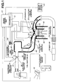
- an air induction control system for controlling airflow into the intake manifold of a variable displacement automotive engine includes a microprocessor control unit 10 of the type commonly used to provide engine control. This engine has four-stroke cycle as its standard cycle.
- Control unit 10 contains microprocessor 12 that includes, in the usual manner, a read only memory (ROM), a random access memory (RAM), a central processor unit (CPU) and an input output (I/O) unit.
- ROM read only memory
- RAM random access memory
- CPU central processor unit
- I/O input output
- Control unit 10 receives in formation from an accelerator position sensor 14 operatively associated with a driver-operable accelerator pedal 16, a throttle sensor 18 operatively associated with an electronic throttle 36, and an engine speed sensor 20.
- Control unit 10 uses a variety of inputs from various sensors, which may include engine coolant temperature, vehicle speed, oxygen concentration, and other sensors known to those skilled in the art. Control unit 10 may operate fuel injection control, spark timing control, air/fuel ratio control, EGR control and other functions. In addition, through a plurality of engine cylinder operators 21 (see Figure 2), control unit 10 is capable of disabling selected cylinders in the engine so as to cause the engine be of a lower effective displacement. For example, with an 8-cylinder engine, the engine may be operated on 4, 5, 6 or 7 cylinders, or even 3 or 2 cylinders, as required. With a 6-cylinder engine, the engine may be operated on 3, 4 or 5 cylinders, or even 2 cylinders, as required.
- control unit 10 With a 4-cylinder engine, the engine may be operated on 2 or 3 cylinders, or even 1 cylinder, as required.
- control unit 10 has also the capability of shifting from the standard cycle. For example, with a 4-stroke cycle engine, the engine may be operated on 8-stroke cycle or 16-stroke cycle, or even 32-stroke cycle, as required.
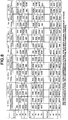
- Figure 8 shows stroke events occurring in 8 crankshaft revolutions if the engine is operated on 4-stroke cycle or 8-stroke cycle or 16-stroke cycle.
- control unit 10 operates electronic valve operators 22 for intake cylinder valves 24 in intake ports 50 and electronic valve operators 26 for exhaust cylinder valves 28 in exhaust ports 52, fuel injectors 30 provided in in take ports 50 and spark plugs 32.
- disabling devices are available for selectively rendering the cylinders of the engine inoperable or deactivating or reactivating them.
- Such devices include hydraulic valve actuators, mechanical valve actuators and electromechanical valve actuators for preventing any of the valves from opening in the disabled or deactivated cylinders, such that gas remains trapped within the cylinder.
- electromechanical valve actuators are disclosed, for example, in US-A 5, 730,091 issued Mar. 24, 1998 to Diehl et al. (Assignee: Ford Global Technologies, Inc.), US-A 5,769,043 issued Jun.
- US-A 5, 873,335 shows an electronic motor control of cylinder valves of an internal combustion engine.
- US-A 6,003,481 shows an electromagnetic valve actuator.
- US-A 5,592,905 and 5,515,818 show an electromechanical variable valve actuator for selectively opening and closing an intake or exhaust valve in an internal combustion engine.
- US-A 5,769,043 shows an electromagnetic valve actuator with a sensor for detecting the cylinder valve motion.
- US-A 5,730,091 shows an electromechanical valve actuator including three electromagnets.
- control unit 10 operates electronic throttle operator 34, which may comprise stepper motor or other type of devices used for positioning electronic throttle 36.
- Control unit 10 operates electronic EGR operator 38, which may comprise stepper motor or other types of devices for positioning EGR control valve 40.
- Air entering intake passage 42 first passes through cross sectional area provided by electronic throttle 36 before entering intake manifold 44. The flowing air is distributed to intake ports 50 for admission during induction stroke of pistons 46 in cylinders 48. Exhaust gases resulting from combustions in power strokes of pistons 46 are discharged out of exhaust ports 52 toward catalytic converter 54 and then to muffler 56.
- control unit 10 may use an accelerator control position function 60.
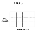
- Accelerator control function 60 enters an electronic throttle position (APO) lookup table as shown in Figure 5.
- the lookup table of Figure 5 combines the instantaneous position of accelerator pedal 16 with engine speed. If desired, the lookup table of Figure 5 may combine not only the instantaneous position of accelerator pedal 16, but also the time rate of change or velocity of the pedal 16. In this case, when the driver steps aggressively on the pedal, the accelerator control function will have a different value than when the driver moves the pedal 16 in a more leisurely fashion.
- the value of the electronic throttle position (APO) drawn from the lookup table will reflect the aggressive or more phlegmatic characteristics of the driver.
- Electronic throttle position APO is used as an in put to a block 62.
- control unit 10 determines a target value of volumetric airflow ratio TQHOST and calculates the product of volumetric airflow ratio TQHOST and maximum air Induction MAXTP to give the result as a target base airflow TTPST.
- Control unit 10 uses a lookup table for conversion from APO to cross sectional area AAPO as indicated by a block 70.
- the relationship between the cross sectional area APPO and throttle position APO can be expressed by the fully drawn characteristic function as shown in Figure 6.
- the value in the lookup table used by control unit 10 for APO to AAPO conversion reflects the characteristic curve of Figure 6.
- Control unit 10 inputs engine displacement VOL# and engine speed and use them in deriving effective flow cross sectional area TGADNV.
- Control unit 10 stores in ROM the number of strokes in a standard cycle (N BSTRK ), e.g., four if a standard cycle is four-stroke cycle. Control unit 10 stores in ROM in formation as to the number of deactivated or disabled cylinders (N DACT ) as well as information as to the number of strokes in a current cycle (N STRK ). Control unit 10 derives a correction factor based on such in formation stored in ROM. Control unit 10 modifies the predetermined function such correction factor to give effective flow cross sectional area TGADNV. At a block 80, control unit 10 uses a lookup table reflecting the relationship as shown in Figure 7 for conversion of TGADNV to volumetric airflow ratio TGHOST. The block 62 outputs the product of volumetric airflow ratio TGHOST and maximum air induction MAXTP as target base airflow TTPST.
- Target base airflow TTPST is used as an in put to a block 64.
- control unit 10 calculates the volume of fresh charge and the volume of EGR charge to be admitted to the engine cylinders. is used as an input to a target throttle control position command generator 66. The results of calculation at block 64 are used as in put to a block 66.
- control unit 10 calculates cross sectional area to be provided at throttle 36 and cross sectional area to be provided at EGR control valve 40. The calculated cross sectional areas are converted to a target throttle control position and a target EGR valve control position.
- the block 66 receives engine speed, engine displacement VOL# and maximum air induction MAXTP. Control unit 10 uses such input information to determine the cross sectional areas at the throttle 36 and the EGR valve 40, respectively.
- Control unit 10 operates electronic throttle operator 34 to position electronic throttle 36 to the target throttle control position and operates electronic EGR operator 38 to position electronic EGR control valve 40.
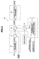
- TGADNV The calculation of TGADNV at block 62 can be understood with reference to control diagram shown in Figure 3.
- Cross sectional area AAPO [cm 2 ] that has been determined as a function (see Figure 6) of electronic throttle position APO [degrees] is divided at a divider block 72 by engine speed to give a value [cm 2 rpm -1 ].
- Number (N DACT ) of deactivated cylinders and number (N STRK ) of strokes in a current cycle are used as inputs to a block 74.
- control unit 10 performs determination of number (N IND ) of induction strokes in two crankshaft revolutions.
- control unit 10 divides the value from the divider block 72 by the value from the multiplier block 76 to give effective flow cross sectional area TGADNV [cm 2 rpm -1 cc -1 ], which is used as the input of block 80 (see Figure 2).
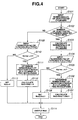
- the flow chart of Figure 4 illustrates a control routine of determination of number N IND of induction strokes in two crankshaft revolutions (at block 74 in Figure 3).
- control unit 10 inputs number N DACT of deactivated cylinders from its ROM.
- control unit 10 determines whether or not number N DACT of deactivated cylinders is greater than zero. If this is the case, the engine is operating on cylinders less than the full complement of cylinders and the routine proceeds to step S103. If this is not the case, the engine is operating on all the cylinders and the routine proceeds to step S109.
- control unit 10 calculates number N ACT of activated cylinders by subtracting number N DACT from 4, which is the number of cylinders of the engine.
- control unit 10 inputs number (N STRK ) of strokes in a current cycle from its ROM. Then, the routine proceeds to interrogation step S105.
- control unit 10 sets N IND equal to N ACT .
- control unit 10 determines that the engine is operating on all of the cylinders (four cylinders, in this example). If, at step S102, control unit 10 determines that the engine is operating on all of the cylinders (four cylinders, in this example), the routine proceeds to step S109. At step S109, control unit 10 inputs number (N STRK ) of strokes in a current cycle from its ROM. Then, the routine proceeds to interrogation step S110.
- control unit 10 determines number N IND* of induction strokes in a cylinder in two crankshaft revolutions in the same manner as performed at step S106. Routine proceeds from step S111 to step S112.
- control unit 10 outputs N IND .
- engine speed that is used at block 72 to divide cross sectional area AAPO remains uncorrected, while displacement used at block 78 to divide the output of the block 72 is corrected in response to the number N DACT of deactivated cylinders and the number N STRK of stroked in a current cycle.
- Another possibility is to leave the total of displacements of cylinders uncorrected and correct engine speed in determining effective flow cross sectional area TGADNV. This is further described in connection with Figure 9.
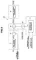
- Figure 9 illustrates a target airflow command generator 62A that may replace that of Figure 3.
- cross sectional area AAPO that has been determined at block 70 is divided at block 82 by total of displacements of cylinders of the engine.
- Number (N DACT ) of deactivated cylinders and number (N STRK ) of strokes in a current cycle are used as inputs to a block 84.
- control unit 10 performs determination of a correction coefficient K E .
- control unit 10 calculates the product of engine speed and the determined correction coefficient K E .
- control unit 10 divides the value from block 82 by the value from multiplier block 86 to give effective flow cross sectional area TGADNV.
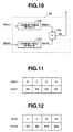
- control unit 10 performs a table lookup operation of a table shown in Figure 11 using N DACT to determine a first coefficient K DACT .
- control unit 10 performs a table lookup operation of a table shown in Figure 12 using N STRK to determine a second coefficient K KSTRK .
- control unit 10 calculates the product K DACT x K KSTRK to give the result as correction coefficient K E .
- the number of engine cylinders, 4 in this example is set as a denominator and the number of activated cylinders is set as a numerator to make a value of the first coefficient K DACT corresponding to the value of N DACT .
- the number N STRK of strokes in a current cycle is set as a denominator and the number of strokes in a 4-stroke cycle is set as a numerator to make a value of the second coefficient K STRK corresponding to the value of N SREK .
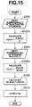
- the flow chart of Figure 13 illustrates a control routine of determination of correction coefficient K E using lookup tables shown in Figures 11 and 12.
- control unit 10 inputs N DACT .
- control unit 10 determines first coefficient K DACT by performing a table lookup operation of table shown in Figure 11 using N DACT .
- control unit 10 inputs N STRK .
- control unit 10 determines second coefficient K STRK by performing a table lookup operation of table shown in Figure 12 using N STRK .
- control unit 10 calculates the product K DACT x K STRK to give the result as correction coefficient K E .
- control unit 10 outputs the determined correction coefficient K E .
- Figure 14 is a similar control diagram to Figure 10. As different from Figure 10, without relying on the lookup tables, first and second coefficients K DACT and K STRK are given by calculating equations.
- control unit calculates the product K DACT x K STRK to give the result as correction coefficient K E .
- control unit 10 inputs N DACT .
- control unit 10 determines first coefficient K DACT by calculating the equation (1).
- control unit 10 inputs N STRK .
- control unit 10 determines second coefficient K STRK by calculating the equation (2).
- control unit 10 calculates the product K DACT x K STRK to give the result as correction coefficient K E .
- control unit 10 outputs the determined correction coefficient K E .
- target airflow command generator 62A shown in Figure 9 engine speed was corrected with correction coefficient K E .
- a target airflow command generator 62B is different from generator 62A in that engine speed is not corrected and correction coefficient K E is multIplied with a value resulting from a divider block 92.
- cross sectional area AAPO that has been determined at block 70 is divided at block 90 by total of displacements of cylinders of the engine.
- Number (N DACT ) of deactivated cylinders and number (N STRK ) of strokes in a current cycle are used as inputs to a block 84.
- the value from block 90 is divided by engine speed.
- control unit 10 multiplies the value from block 92 with correction coefficient K E to give effective flow cross sectional area TGADNV.
Landscapes
- Engineering & Computer Science (AREA)
- Mechanical Engineering (AREA)
- General Engineering & Computer Science (AREA)
- Chemical & Material Sciences (AREA)
- Combustion & Propulsion (AREA)
- Combined Controls Of Internal Combustion Engines (AREA)
- Output Control And Ontrol Of Special Type Engine (AREA)
- Electrical Control Of Air Or Fuel Supplied To Internal-Combustion Engine (AREA)
- Valve Device For Special Equipments (AREA)
- Characterised By The Charging Evacuation (AREA)
Applications Claiming Priority (2)
| Application Number | Priority Date | Filing Date | Title |
|---|---|---|---|
| JP29433899A JP3817991B2 (ja) | 1999-10-15 | 1999-10-15 | 内燃機関の制御装置 |
| JP29433899 | 1999-10-15 |
Publications (3)
| Publication Number | Publication Date |
|---|---|
| EP1092855A2 true EP1092855A2 (fr) | 2001-04-18 |
| EP1092855A3 EP1092855A3 (fr) | 2002-10-09 |
| EP1092855B1 EP1092855B1 (fr) | 2006-11-29 |
Family
ID=17806420
Family Applications (1)
| Application Number | Title | Priority Date | Filing Date |
|---|---|---|---|
| EP00122445A Expired - Lifetime EP1092855B1 (fr) | 1999-10-15 | 2000-10-13 | Système de commande d'admission d'air pour moteur à combustion interne à déplacement variable |
Country Status (4)
| Country | Link |
|---|---|
| US (1) | US6363907B1 (fr) |
| EP (1) | EP1092855B1 (fr) |
| JP (1) | JP3817991B2 (fr) |
| DE (1) | DE60032094T2 (fr) |
Cited By (5)
| Publication number | Priority date | Publication date | Assignee | Title |
|---|---|---|---|---|
| GB2355494B (en) * | 1999-10-18 | 2004-01-14 | Ford Global Tech Inc | Direct injection engine system |
| GB2355496B (en) * | 1999-10-18 | 2004-02-18 | Ford Global Tech Inc | Direct injection engine system and method |
| EP1249593A3 (fr) * | 2001-04-13 | 2004-12-29 | Nissan Motor Co., Ltd. | Système et méthode de commande de carburant pour moteur à combustion interne multicylindre |
| GB2415744A (en) * | 2004-05-13 | 2006-01-04 | Anthony Edgar Blackburn | I.c. engine changeable between 8-stroke and 4-stroke cycles |
| CN108730050A (zh) * | 2017-04-13 | 2018-11-02 | 通用汽车环球科技运作有限责任公司 | 用于使用空气流量致动器控制发动机的方法 |
Families Citing this family (57)
| Publication number | Priority date | Publication date | Assignee | Title |
|---|---|---|---|---|
| SE521741C2 (sv) * | 1999-06-24 | 2003-12-02 | Volvo Personvagnar Ab | Metod för att styra en flertaktsmotor |
| US6619258B2 (en) * | 2002-01-15 | 2003-09-16 | Delphi Technologies, Inc. | System for controllably disabling cylinders in an internal combustion engine |
| US20040069272A1 (en) * | 2002-10-10 | 2004-04-15 | Allen Jeffrey James | Displacement on demand torque smoothing using engine speed control |
| US7028650B2 (en) * | 2004-03-19 | 2006-04-18 | Ford Global Technologies, Llc | Electromechanical valve operating conditions by control method |
| US7079935B2 (en) * | 2004-03-19 | 2006-07-18 | Ford Global Technologies, Llc | Valve control for an engine with electromechanically actuated valves |
| US7555896B2 (en) * | 2004-03-19 | 2009-07-07 | Ford Global Technologies, Llc | Cylinder deactivation for an internal combustion engine |
| US7017539B2 (en) * | 2004-03-19 | 2006-03-28 | Ford Global Technologies Llc | Engine breathing in an engine with mechanical and electromechanical valves |
| US7107946B2 (en) * | 2004-03-19 | 2006-09-19 | Ford Global Technologies, Llc | Electromechanically actuated valve control for an internal combustion engine |
| US7240663B2 (en) * | 2004-03-19 | 2007-07-10 | Ford Global Technologies, Llc | Internal combustion engine shut-down for engine having adjustable valves |
| US7021289B2 (en) * | 2004-03-19 | 2006-04-04 | Ford Global Technology, Llc | Reducing engine emissions on an engine with electromechanical valves |
| US7066121B2 (en) * | 2004-03-19 | 2006-06-27 | Ford Global Technologies, Llc | Cylinder and valve mode control for an engine with valves that may be deactivated |
| US7140355B2 (en) * | 2004-03-19 | 2006-11-28 | Ford Global Technologies, Llc | Valve control to reduce modal frequencies that may cause vibration |
| US6938598B1 (en) | 2004-03-19 | 2005-09-06 | Ford Global Technologies, Llc | Starting an engine with electromechanical valves |
| US7031821B2 (en) * | 2004-03-19 | 2006-04-18 | Ford Global Technologies, Llc | Electromagnetic valve control in an internal combustion engine with an asymmetric exhaust system design |
| US7055483B2 (en) * | 2004-03-19 | 2006-06-06 | Ford Global Technologies, Llc | Quick starting engine with electromechanical valves |
| US7032545B2 (en) | 2004-03-19 | 2006-04-25 | Ford Global Technologies, Llc | Multi-stroke cylinder operation in an internal combustion engine |
| US7032581B2 (en) * | 2004-03-19 | 2006-04-25 | Ford Global Technologies, Llc | Engine air-fuel control for an engine with valves that may be deactivated |
| US7194993B2 (en) * | 2004-03-19 | 2007-03-27 | Ford Global Technologies, Llc | Starting an engine with valves that may be deactivated |
| US7383820B2 (en) * | 2004-03-19 | 2008-06-10 | Ford Global Technologies, Llc | Electromechanical valve timing during a start |
| US7063062B2 (en) * | 2004-03-19 | 2006-06-20 | Ford Global Technologies, Llc | Valve selection for an engine operating in a multi-stroke cylinder mode |
| US7107947B2 (en) * | 2004-03-19 | 2006-09-19 | Ford Global Technologies, Llc | Multi-stroke cylinder operation in an internal combustion engine |
| US7165391B2 (en) * | 2004-03-19 | 2007-01-23 | Ford Global Technologies, Llc | Method to reduce engine emissions for an engine capable of multi-stroke operation and having a catalyst |
| US7128043B2 (en) | 2004-03-19 | 2006-10-31 | Ford Global Technologies, Llc | Electromechanically actuated valve control based on a vehicle electrical system |
| US7559309B2 (en) * | 2004-03-19 | 2009-07-14 | Ford Global Technologies, Llc | Method to start electromechanical valves on an internal combustion engine |
| US7072758B2 (en) * | 2004-03-19 | 2006-07-04 | Ford Global Technologies, Llc | Method of torque control for an engine with valves that may be deactivated |
| US7128687B2 (en) * | 2004-03-19 | 2006-10-31 | Ford Global Technologies, Llc | Electromechanically actuated valve control for an internal combustion engine |
| US7467614B2 (en) | 2004-12-29 | 2008-12-23 | Honeywell International Inc. | Pedal position and/or pedal change rate for use in control of an engine |
| US8430067B2 (en) * | 2005-05-12 | 2013-04-30 | Ford Global Technologies, Llc | Engine starting for engine having adjustable valve operation |
| US7389773B2 (en) | 2005-08-18 | 2008-06-24 | Honeywell International Inc. | Emissions sensors for fuel control in engines |
| EP2132411A4 (fr) | 2007-04-09 | 2014-11-05 | Seth Chandan Kumar | Moteur split-cycle (à cycle scindé) à allumage commandé rotatif et capacité variable |
| US8132546B2 (en) * | 2008-05-08 | 2012-03-13 | Ford Global Technologies, Llc | Control strategy for multi-stroke engine system |
| US8133153B2 (en) * | 2008-06-25 | 2012-03-13 | Ford Global Technologies, Llc | Transmission scheduling for multi-stroke engine |
| US7963267B2 (en) * | 2008-07-17 | 2011-06-21 | Ford Global Technologies, Llc | Multi-stroke variable displacement engine |
| US8060290B2 (en) | 2008-07-17 | 2011-11-15 | Honeywell International Inc. | Configurable automotive controller |
| CN102325976A (zh) | 2008-12-22 | 2012-01-18 | 卡特彼勒公司 | 执行稀燃6冲程循环的发动机控制系统 |
| US8620461B2 (en) | 2009-09-24 | 2013-12-31 | Honeywell International, Inc. | Method and system for updating tuning parameters of a controller |
| US8504175B2 (en) | 2010-06-02 | 2013-08-06 | Honeywell International Inc. | Using model predictive control to optimize variable trajectories and system control |
| US9677493B2 (en) | 2011-09-19 | 2017-06-13 | Honeywell Spol, S.R.O. | Coordinated engine and emissions control system |
| US9650934B2 (en) | 2011-11-04 | 2017-05-16 | Honeywell spol.s.r.o. | Engine and aftertreatment optimization system |
| US20130111905A1 (en) | 2011-11-04 | 2013-05-09 | Honeywell Spol. S.R.O. | Integrated optimization and control of an engine and aftertreatment system |
| US9200587B2 (en) * | 2012-04-27 | 2015-12-01 | Tula Technology, Inc. | Look-up table based skip fire engine control |
| US8443769B1 (en) | 2012-05-18 | 2013-05-21 | Raymond F. Lippitt | Internal combustion engines |
| US9303559B2 (en) | 2012-10-16 | 2016-04-05 | Raymond F. Lippitt | Internal combustion engines |
| WO2015069536A1 (fr) | 2013-11-05 | 2015-05-14 | Lippitt Raymond F | Moteur à train d'engrenages central |
| US9217365B2 (en) | 2013-11-15 | 2015-12-22 | Raymond F. Lippitt | Inverted V-8 internal combustion engine and method of operating the same modes |
| US9664044B2 (en) | 2013-11-15 | 2017-05-30 | Raymond F. Lippitt | Inverted V-8 I-C engine and method of operating same in a vehicle |
| EP3051367B1 (fr) | 2015-01-28 | 2020-11-25 | Honeywell spol s.r.o. | Approche et système de manipulation de contraintes pour des perturbations mesurées avec une prévisualisation incertaine |
| EP3056706A1 (fr) | 2015-02-16 | 2016-08-17 | Honeywell International Inc. | Approche de modélisation de système de post-traitement et d'identification de modèle |
| EP3091212A1 (fr) | 2015-05-06 | 2016-11-09 | Honeywell International Inc. | Approche d'identification pour modèles de valeurs moyennes de moteurs à combustion interne |
| EP3125052B1 (fr) | 2015-07-31 | 2020-09-02 | Garrett Transportation I Inc. | Résolveur de programme quadratique pour mpc utilisant une commande variable |
| US10272779B2 (en) | 2015-08-05 | 2019-04-30 | Garrett Transportation I Inc. | System and approach for dynamic vehicle speed optimization |
| US10415492B2 (en) | 2016-01-29 | 2019-09-17 | Garrett Transportation I Inc. | Engine system with inferential sensor |
| US10036338B2 (en) | 2016-04-26 | 2018-07-31 | Honeywell International Inc. | Condition-based powertrain control system |
| US10124750B2 (en) | 2016-04-26 | 2018-11-13 | Honeywell International Inc. | Vehicle security module system |
| EP3548729B1 (fr) | 2016-11-29 | 2023-02-22 | Garrett Transportation I Inc. | Capteur de flux inférentiel |
| US11057213B2 (en) | 2017-10-13 | 2021-07-06 | Garrett Transportation I, Inc. | Authentication system for electronic control unit on a bus |
| US11480122B1 (en) | 2021-05-24 | 2022-10-25 | Ford Global Technologies, Llc | Methods and systems for reducing engine exhaust emissions |
Citations (12)
| Publication number | Priority date | Publication date | Assignee | Title |
|---|---|---|---|---|
| US4550704A (en) | 1983-04-12 | 1985-11-05 | Robert Bosch Gmbh | Multi-cylinder internal combustion engine having disconnectable groups of cylinders |
| US5005539A (en) | 1989-05-11 | 1991-04-09 | Isuzu Ceramics Research Institute Co., Ltd. | Engine cycle control system |
| US5022353A (en) | 1989-04-26 | 1991-06-11 | Isuzu Ceramics Research Institute Co., Ltd. | Variable-cycle engine |
| US5113805A (en) | 1989-12-12 | 1992-05-19 | Isuzu Ceramics Research Institute Co., Ltd. | Variable-cycle engine |
| JPH06159110A (ja) | 1992-11-27 | 1994-06-07 | Nippondenso Co Ltd | 車両用駆動力制御装置 |
| JPH0874610A (ja) | 1994-09-01 | 1996-03-19 | Toyota Motor Corp | 可変気筒エンジンの制御装置 |
| US5515818A (en) | 1993-12-15 | 1996-05-14 | Machine Research Corporation Of Chicago | Electromechanical variable valve actuator |
| US5540633A (en) | 1993-09-16 | 1996-07-30 | Toyota Jidosha Kabushiki Kaisha | Control device for variable displacement engine |
| US5730091A (en) | 1996-11-12 | 1998-03-24 | Ford Global Technologies, Inc. | Soft landing electromechanically actuated engine valve |
| US5769043A (en) | 1997-05-08 | 1998-06-23 | Siemens Automotive Corporation | Method and apparatus for detecting engine valve motion |
| US5873335A (en) | 1998-01-09 | 1999-02-23 | Siemens Automotive Corporation | Engine valve actuation control system |
| US6003481A (en) | 1996-09-04 | 1999-12-21 | Fev Motorentechnik Gmbh & Co. Kommanditgesellschaft | Electromagnetic actuator with impact damping |
Family Cites Families (5)
| Publication number | Priority date | Publication date | Assignee | Title |
|---|---|---|---|---|
| US4873641A (en) * | 1986-07-03 | 1989-10-10 | Nissan Motor Company, Limited | Induction volume sensing arrangement for an internal combustion engine or the like |
| US5398544A (en) * | 1993-12-23 | 1995-03-21 | Ford Motor Company | Method and system for determining cylinder air charge for variable displacement internal combustion engine |
| US5778858A (en) * | 1996-12-17 | 1998-07-14 | Dudley Frank | Fuel injection split engine |
| US5826563A (en) * | 1997-07-28 | 1998-10-27 | General Electric Company | Diesel engine cylinder skip firing system |
| WO1999014476A1 (fr) * | 1997-09-17 | 1999-03-25 | Robert Bosch Gmbh | Procede et dispositif pour determiner le degre d'admission de gaz d'un moteur a combustion interne |
-
1999
- 1999-10-15 JP JP29433899A patent/JP3817991B2/ja not_active Expired - Fee Related
-
2000
- 2000-10-11 US US09/686,992 patent/US6363907B1/en not_active Expired - Fee Related
- 2000-10-13 EP EP00122445A patent/EP1092855B1/fr not_active Expired - Lifetime
- 2000-10-13 DE DE60032094T patent/DE60032094T2/de not_active Expired - Lifetime
Patent Citations (14)
| Publication number | Priority date | Publication date | Assignee | Title |
|---|---|---|---|---|
| US4550704A (en) | 1983-04-12 | 1985-11-05 | Robert Bosch Gmbh | Multi-cylinder internal combustion engine having disconnectable groups of cylinders |
| US5022353A (en) | 1989-04-26 | 1991-06-11 | Isuzu Ceramics Research Institute Co., Ltd. | Variable-cycle engine |
| US5005539A (en) | 1989-05-11 | 1991-04-09 | Isuzu Ceramics Research Institute Co., Ltd. | Engine cycle control system |
| US5113805A (en) | 1989-12-12 | 1992-05-19 | Isuzu Ceramics Research Institute Co., Ltd. | Variable-cycle engine |
| JPH06159110A (ja) | 1992-11-27 | 1994-06-07 | Nippondenso Co Ltd | 車両用駆動力制御装置 |
| US5540633A (en) | 1993-09-16 | 1996-07-30 | Toyota Jidosha Kabushiki Kaisha | Control device for variable displacement engine |
| US5515818A (en) | 1993-12-15 | 1996-05-14 | Machine Research Corporation Of Chicago | Electromechanical variable valve actuator |
| US5592905A (en) | 1993-12-15 | 1997-01-14 | Machine Research Corporation Of Chicago | Electromechanical variable valve actuator |
| JPH0874610A (ja) | 1994-09-01 | 1996-03-19 | Toyota Motor Corp | 可変気筒エンジンの制御装置 |
| US5562086A (en) | 1994-09-01 | 1996-10-08 | Toyota Jidosha Kabushiki Kaisha | Control device of a varable cylinder engine |
| US6003481A (en) | 1996-09-04 | 1999-12-21 | Fev Motorentechnik Gmbh & Co. Kommanditgesellschaft | Electromagnetic actuator with impact damping |
| US5730091A (en) | 1996-11-12 | 1998-03-24 | Ford Global Technologies, Inc. | Soft landing electromechanically actuated engine valve |
| US5769043A (en) | 1997-05-08 | 1998-06-23 | Siemens Automotive Corporation | Method and apparatus for detecting engine valve motion |
| US5873335A (en) | 1998-01-09 | 1999-02-23 | Siemens Automotive Corporation | Engine valve actuation control system |
Cited By (6)
| Publication number | Priority date | Publication date | Assignee | Title |
|---|---|---|---|---|
| GB2355494B (en) * | 1999-10-18 | 2004-01-14 | Ford Global Tech Inc | Direct injection engine system |
| GB2355496B (en) * | 1999-10-18 | 2004-02-18 | Ford Global Tech Inc | Direct injection engine system and method |
| EP1249593A3 (fr) * | 2001-04-13 | 2004-12-29 | Nissan Motor Co., Ltd. | Système et méthode de commande de carburant pour moteur à combustion interne multicylindre |
| GB2415744A (en) * | 2004-05-13 | 2006-01-04 | Anthony Edgar Blackburn | I.c. engine changeable between 8-stroke and 4-stroke cycles |
| GB2415744B (en) * | 2004-05-13 | 2008-10-29 | Anthony Edgar Blackburn | Engine cycles |
| CN108730050A (zh) * | 2017-04-13 | 2018-11-02 | 通用汽车环球科技运作有限责任公司 | 用于使用空气流量致动器控制发动机的方法 |
Also Published As
| Publication number | Publication date |
|---|---|
| EP1092855B1 (fr) | 2006-11-29 |
| EP1092855A3 (fr) | 2002-10-09 |
| DE60032094T2 (de) | 2007-03-08 |
| DE60032094D1 (de) | 2007-01-11 |
| JP2001115865A (ja) | 2001-04-24 |
| US6363907B1 (en) | 2002-04-02 |
| JP3817991B2 (ja) | 2006-09-06 |
Similar Documents
| Publication | Publication Date | Title |
|---|---|---|
| EP1092855B1 (fr) | Système de commande d'admission d'air pour moteur à combustion interne à déplacement variable | |
| EP0659995B1 (fr) | Méthode et système pour déterminer la charge d'air pour cylindre d'un moteur à combustion interne | |
| US6237563B1 (en) | Method for controlling an internal combustion engine | |
| US7464674B2 (en) | Induction air acoustics management for internal combustion engine | |
| US7121233B2 (en) | Control apparatus for an internal combustion engine | |
| US7236874B2 (en) | Torque control apparatus and vehicle control system having the same | |
| US10132260B2 (en) | Method of continuously calculating trapped and scavenged air per cylinder | |
| EP1249593B1 (fr) | Système et méthode de commande de carburant pour moteur à combustion interne multicylindre | |
| JPS6045740A (ja) | 気筒数制御エンジンの回転数検出装置 | |
| US6189524B1 (en) | Method and device for monitoring an internal combustion engine | |
| JP2568785B2 (ja) | 燃料噴射式内燃機関における遅延減少装置および方法 | |
| US6678608B2 (en) | Robust interpolation method for improved automative engine control during transient engine operation | |
| US7043349B2 (en) | Method and system for inferring exhaust temperature of a variable compression ratio engine | |
| JP2806545B2 (ja) | 自動変速機の変速制御方法 | |
| JP2008274884A (ja) | 内燃機関の制御装置 | |
| JP2000080930A (ja) | 電制スロットル式内燃機関のスロットル制御装置 | |
| GB2389626A (en) | Inferring intake manifold pressure of a variable compression ratio i.c. engine | |
| CN114060156B (zh) | 辅助节流阀控制系统和方法 | |
| US8219301B2 (en) | Control device for internal combustion engine | |
| CA1297359C (fr) | Procede de regulation de l'alimentation au demarrage d'un moteur a combustioninterne | |
| JPH10252533A (ja) | 内燃機関の燃料カット制御装置 | |
| JPH05340275A (ja) | 内燃機関の吸気制御装置 | |
| JPH11247698A (ja) | 内燃機関用電子制御燃料噴射装置のリンプホーム制御装置 | |
| JPS61205344A (ja) | デイ−ゼルエンジンの排気ガス浄化装置 | |
| JPH09209812A (ja) | 内燃機関の燃料噴射制御装置 |
Legal Events
| Date | Code | Title | Description |
|---|---|---|---|
| PUAI | Public reference made under article 153(3) epc to a published international application that has entered the european phase |
Free format text: ORIGINAL CODE: 0009012 |
|
| 17P | Request for examination filed |
Effective date: 20001013 |
|
| AK | Designated contracting states |
Kind code of ref document: A2 Designated state(s): AT BE CH CY DE DK ES FI FR GB GR IE IT LI LU MC NL PT SE |
|
| AX | Request for extension of the european patent |
Free format text: AL;LT;LV;MK;RO;SI |
|
| PUAL | Search report despatched |
Free format text: ORIGINAL CODE: 0009013 |
|
| AK | Designated contracting states |
Kind code of ref document: A3 Designated state(s): AT BE CH CY DE DK ES FI FR GB GR IE IT LI LU MC NL PT SE |
|
| AX | Request for extension of the european patent |
Free format text: AL;LT;LV;MK;RO;SI |
|
| AKX | Designation fees paid |
Designated state(s): DE FR GB |
|
| GRAP | Despatch of communication of intention to grant a patent |
Free format text: ORIGINAL CODE: EPIDOSNIGR1 |
|
| GRAS | Grant fee paid |
Free format text: ORIGINAL CODE: EPIDOSNIGR3 |
|
| GRAA | (expected) grant |
Free format text: ORIGINAL CODE: 0009210 |
|
| AK | Designated contracting states |
Kind code of ref document: B1 Designated state(s): DE FR GB |
|
| REG | Reference to a national code |
Ref country code: GB Ref legal event code: FG4D |
|
| REF | Corresponds to: |
Ref document number: 60032094 Country of ref document: DE Date of ref document: 20070111 Kind code of ref document: P |
|
| ET | Fr: translation filed | ||
| PLBE | No opposition filed within time limit |
Free format text: ORIGINAL CODE: 0009261 |
|
| STAA | Information on the status of an ep patent application or granted ep patent |
Free format text: STATUS: NO OPPOSITION FILED WITHIN TIME LIMIT |
|
| 26N | No opposition filed |
Effective date: 20070830 |
|
| PGFP | Annual fee paid to national office [announced via postgrant information from national office to epo] |
Ref country code: DE Payment date: 20101006 Year of fee payment: 11 |
|
| PGFP | Annual fee paid to national office [announced via postgrant information from national office to epo] |
Ref country code: GB Payment date: 20101013 Year of fee payment: 11 |
|
| PGFP | Annual fee paid to national office [announced via postgrant information from national office to epo] |
Ref country code: FR Payment date: 20111103 Year of fee payment: 12 |
|
| GBPC | Gb: european patent ceased through non-payment of renewal fee |
Effective date: 20121013 |
|
| REG | Reference to a national code |
Ref country code: FR Ref legal event code: ST Effective date: 20130628 |
|
| PG25 | Lapsed in a contracting state [announced via postgrant information from national office to epo] |
Ref country code: DE Free format text: LAPSE BECAUSE OF NON-PAYMENT OF DUE FEES Effective date: 20130501 Ref country code: GB Free format text: LAPSE BECAUSE OF NON-PAYMENT OF DUE FEES Effective date: 20121013 |
|
| REG | Reference to a national code |
Ref country code: DE Ref legal event code: R119 Ref document number: 60032094 Country of ref document: DE Effective date: 20130501 |
|
| PG25 | Lapsed in a contracting state [announced via postgrant information from national office to epo] |
Ref country code: FR Free format text: LAPSE BECAUSE OF NON-PAYMENT OF DUE FEES Effective date: 20121031 |