EP1092916A2 - Beleuchtungs-Einrichtung und Verfahren - Google Patents
Beleuchtungs-Einrichtung und Verfahren Download PDFInfo
- Publication number
- EP1092916A2 EP1092916A2 EP99309634A EP99309634A EP1092916A2 EP 1092916 A2 EP1092916 A2 EP 1092916A2 EP 99309634 A EP99309634 A EP 99309634A EP 99309634 A EP99309634 A EP 99309634A EP 1092916 A2 EP1092916 A2 EP 1092916A2
- Authority
- EP
- European Patent Office
- Prior art keywords
- housing
- frame
- ceiling
- baffle
- bottom edge
- Prior art date
- Legal status (The legal status is an assumption and is not a legal conclusion. Google has not performed a legal analysis and makes no representation as to the accuracy of the status listed.)
- Granted
Links
- 238000000034 method Methods 0.000 title claims abstract description 12
- 230000007246 mechanism Effects 0.000 claims abstract description 26
- 230000000712 assembly Effects 0.000 description 8
- 238000000429 assembly Methods 0.000 description 8
- 238000009434 installation Methods 0.000 description 5
- 239000000463 material Substances 0.000 description 2
- 230000000903 blocking effect Effects 0.000 description 1
- 239000000945 filler Substances 0.000 description 1
- 230000005484 gravity Effects 0.000 description 1
Images


Classifications
-
- F—MECHANICAL ENGINEERING; LIGHTING; HEATING; WEAPONS; BLASTING
- F21—LIGHTING
- F21S—NON-PORTABLE LIGHTING DEVICES; SYSTEMS THEREOF; VEHICLE LIGHTING DEVICES SPECIALLY ADAPTED FOR VEHICLE EXTERIORS
- F21S8/00—Lighting devices intended for fixed installation
- F21S8/02—Lighting devices intended for fixed installation of recess-mounted type, e.g. downlighters
- F21S8/026—Lighting devices intended for fixed installation of recess-mounted type, e.g. downlighters intended to be recessed in a ceiling or like overhead structure, e.g. suspended ceiling
-
- F—MECHANICAL ENGINEERING; LIGHTING; HEATING; WEAPONS; BLASTING
- F21—LIGHTING
- F21S—NON-PORTABLE LIGHTING DEVICES; SYSTEMS THEREOF; VEHICLE LIGHTING DEVICES SPECIALLY ADAPTED FOR VEHICLE EXTERIORS
- F21S8/00—Lighting devices intended for fixed installation
- F21S8/02—Lighting devices intended for fixed installation of recess-mounted type, e.g. downlighters
-
- F—MECHANICAL ENGINEERING; LIGHTING; HEATING; WEAPONS; BLASTING
- F21—LIGHTING
- F21V—FUNCTIONAL FEATURES OR DETAILS OF LIGHTING DEVICES OR SYSTEMS THEREOF; STRUCTURAL COMBINATIONS OF LIGHTING DEVICES WITH OTHER ARTICLES, NOT OTHERWISE PROVIDED FOR
- F21V21/00—Supporting, suspending, or attaching arrangements for lighting devices; Hand grips
- F21V21/02—Wall, ceiling, or floor bases; Fixing pendants or arms to the bases
- F21V21/04—Recessed bases
-
- F—MECHANICAL ENGINEERING; LIGHTING; HEATING; WEAPONS; BLASTING
- F21—LIGHTING
- F21V—FUNCTIONAL FEATURES OR DETAILS OF LIGHTING DEVICES OR SYSTEMS THEREOF; STRUCTURAL COMBINATIONS OF LIGHTING DEVICES WITH OTHER ARTICLES, NOT OTHERWISE PROVIDED FOR
- F21V21/00—Supporting, suspending, or attaching arrangements for lighting devices; Hand grips
- F21V21/14—Adjustable mountings
- F21V21/30—Pivoted housings or frames
-
- F—MECHANICAL ENGINEERING; LIGHTING; HEATING; WEAPONS; BLASTING
- F21—LIGHTING
- F21V—FUNCTIONAL FEATURES OR DETAILS OF LIGHTING DEVICES OR SYSTEMS THEREOF; STRUCTURAL COMBINATIONS OF LIGHTING DEVICES WITH OTHER ARTICLES, NOT OTHERWISE PROVIDED FOR
- F21V23/00—Arrangement of electric circuit elements in or on lighting devices
- F21V23/02—Arrangement of electric circuit elements in or on lighting devices the elements being transformers, impedances or power supply units, e.g. a transformer with a rectifier
Definitions
- the present invention is related to an apparatus and method for lighting. More specifically, the present invention is related to an apparatus for lighting where the bottom edge of a housing is hidden by a frame.
- Light has always provided the ability for people to see the world around them. As such, it is a necessity for people to see indoors. But lighting in and of itself has also taken on an aesthetic element, where the lighting is designed to be part of the structure it illuminates in a way that is unobtrusive and unnoticeable, or conforms as much as possible to its surroundings.
- the lighting apparatus is desired to be as unnoticeable as possible while serving its purpose of illuminating the products being sold.
- Recessed lighting is commonly used to accomplish this purpose.
- the housing is inserted into a wall, ceiling or floor, where the housing holds the light itself.
- the housing is outfitted with a frame which is used to hold lighting in the wall, ceiling or floor.
- the housing has fitted inside the frame, creating additional edges and thus lines that disrupt the aesthetically pleasing look of a smooth floor, ceiling or wall. The present invention removes these lines to provide a more smooth and continuous look to the wall, ceiling or floor in which the lighting apparatus is disposed.
- the present invention pertains to an apparatus for lighting which fits into a wall, ceiling or floor.
- the apparatus comprises a housing having a bottom edge and at least one mechanism for holding a light.
- the housing has a depth.
- the apparatus comprises a frame having an opening having a width larger than the depth through which the housing can fit.
- the housing fits about the frame wherein the bottom edge is hidden by the frame.
- the present invention pertains to a method for installing an apparatus for lighting.
- the method comprises the steps of placing a frame having an opening into a space in a ceiling of a room. Then there is the step of introducing a housing through the opening in the frame into the ceiling. Next there is the step of fitting a bottom edge of the housing about a ridge of the frame which extends inwards into the ceiling wherein the bottom edge is hidden by the frame. Then there is the step of setting at least one mechanism for holding a light in the housing.
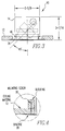
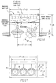
- the apparatus comprises a housing 14 having a bottom edge 16 and at least one mechanism for holding a light 20.
- the housing 14 has a depth.
- the apparatus comprises a frame 22 having an opening 24 having a width larger than the depth through which the housing 14 can fit.
- the housing 14 fits about the frame 22 wherein the bottom edge 16 is hidden by the frame 22.
- the frame 22 has a flange 26 on which spackle 28 is placed.
- the flange 26 is preferably perforated but need not be perforated.
- the apparatus preferably includes a screw 30 or bolt or rivet which extends through the frame 22 to hold the frame 22 to the wall, ceiling 12 or floor.
- a screw can also be used to secure the housing 14 to the ceiling, floor or wall.
- the frame 22 has a ridge 36 which extends inwards. The bottom edge 16 of the housing 14 fits about the ridge 36. Alternatively, the housing can fit on the frame 22 by gravity in the ceiling 12.
- the apparatus preferably includes a transformer 32 connected to the light holding mechanism 18.
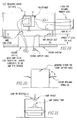
- the transformer 32 is disposed on the top, above or side of the housing 14 and is accessible through the housing 14 when the transformer 32 and housing 14 are installed or removed in the floor, ceiling 12 or wall, as shown in figure 16.
- the transformer 32 is remote from the housing 14, and the apparatus includes wiring 34 connecting the transformer 32 to the light holding mechanism 18.
- the wiring 34 from the transformer 32 that is disposed outside of the housing 14 can be held in a flexible conduit 66, as shown in figure 7, which passes through a wire access 62 on the side of the housing 14.
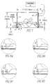
- the light holding mechanism 18 minds includes a gimbal ring assembly 44 or yoke.
- the light holding mechanism 18 can include a shielding cone 46.
- the housing 14 can include a spill shield 38, as shown in figure 17, or lens 40, as shown in figure 18, disposed below the light holding mechanism 18.
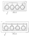
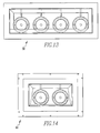
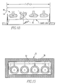
- the housing 14 can include either a four-sided removable symmetric baffle 48 shown in figure 10, a one-sided asymmetric baffle 50 shown in figure 11, a four-sided removable asymmetric baffle 52 shown in figure 15, a two-sided symmetric baffle 54 shown in figure 9, a two-sided asymmetric baffle 56 shown in figure 12, a two-sided asymmetric baffle with symmetrical ends 58 shown in figure 13, or a truncated two-sided asymmetric baffle with asymmetric ends 60 shown in figure 14.
- the baffle can be part of the housing 14, as shown in figures 8c and 8d, or alternatively, the baffle can be part of the frame 22, as shown in figures 8a and 8b.
- the frame 22 can have the flange omitted.
- the frame 22 has a seat 64 which extends outward and rests on the inner or top surface of the ceiling 12 to hold the frame 22 to the ceiling.
- the housing 14 then fits on top of the frame 22 so the bottom edge 16 is not visible.
- the present invention pertains to a method for installing an apparatus for lighting.
- the method comprises the steps of placing a frame 22 having an opening 24 into a space in a ceiling 12 of a room. Then there is the step of introducing a housing 14 through the opening 24 in the frame 22 into the ceiling 12. Next there is the step of fitting a bottom edge 16 of the housing 14 about a ridge 36 of the frame 22 which extends inwards into the ceiling 12 wherein the bottom edge 16 is hidden by the frame 22. Then there is the step of setting at least one mechanism for holding a light 20 in the housing 14.
- the placing step includes the step of spackling spackle 28 onto a flange 26 of the frame 22.
- the setting step there is preferably the step of positioning a baffle on the housing 14 below the light holding mechanism 18.
- a wall, ceiling 12 or floor is prepared for receipt of a lighting apparatus 10.
- a lighting apparatus 10 For purposes of discussion, reference will only be made to a ceiling 12, but the following description is also applicable for a wall or floor.) Basically, this means that an opening is created in the ceiling 12 in which the lighting apparatus 10 will be located.
- a frame 22 of the lighting apparatus 10 is placed into the opening 24 in the ceiling 12.
- the frame 22 has a perforated flange 26 which extends about its circumference that contacts the bottom of the ceiling 12 about the opening 24.
- the frame 22 is held in place with the flange 26 in contact against the ceiling 12, and mounting screws 30 are placed through respective perforations in the flange 26.
- the mounting screws 30 penetrate the ceiling 12 material and blocking to hold the frame 22 in place.
- Spackle 28 is placed over the perforated flange 26 to cover it from view by people in the room looking up at the lighting apparatus 10 in the ceiling 12.
- the housing 14 of the lighting apparatus 10 is then inserted through the opening 24 in the frame 22 so the housing 14 is inside the ceiling 12.
- the depth of the housing 14 is less than the width of the opening 24 of the frame 22 so the housing 14 can fit through the opening 24. It may be that the housing 14 has to be rotated or turned so that portion of the housing 14 whose depth is less than the width of the opening 24 is exposed to the opening 24 to fit through the opening 24, but the housing 14 can then be realigned after it passes through the opening 24 of the frame 22 to be properly positioned on the frame 22.
- the housing 14 is made of two or more parts to allow it to fit through the opening 24 of the frame 22.
- the different parts of the housing 14 will then be reassembled after they have fit through the opening 24 and are in the ceiling 12.
- the housing 14 is inserted into the ceiling 12 through the opening 24 of the frame 22, it is aligned so its bottom edge 16 is positioned about a ridge 36 of the frame 22 which extends in words from the frame 22 into the ceiling 12.
- the housing 14 is lowered down onto the top surface (the non-exposed portion) of the ceiling 12 so the ridge 36 of the frame 22 is now inside of the housing 14 bottom edge 16 circumference.
- the housing 14 can be either snapped into place on the ridge 36 that snaps on the ridge 36, or can be screwed or riveted into place to the ridge 36 to be held securely in the ceiling 12.
- the housing 14 is snapped or screwed into the ridge 36 so that the housing 14 at some later time, if desired, can be removed from the ceiling 12 through the opening 24 in the frame 22 in the opposite way that the housing 14 was put in the ceiling 12.
- the frame 22 hides the bottom edge 16 of the housing 14 from view and eliminates the line or edge or space created between a frame 22 in the housing 14 if the housing 14 was positioned inside of the ridge 36 of the frame 22.
- a light holding mechanism 18 can then be installed into the housing 14. Typically, there can be unlimited, and preferably from 1 to 30 light holding mechanisms 18. Alternatively, the light holding mechanisms 18 can already be installed in the housing 14 before it is inserted into the opening 24 in the frame 22, if it is so desired, and if the presence of the light holding mechanism 18 does not extend the effective depth of the housing 14 to such a degree that the housing 14 with the light holding mechanism 18 can no longer fit through the opening 24 in the frame 22.
- the light holding mechanism 18 can be for instance a gimbal ring assembly 44.
- the various gimbal ring assemblies, or yokes can be positioned properly with the lights 20 installed in the gimbal ring assemblies or yokes.
- the gimbal ring assemblies or yokes effectively do extend the effective depth of the housing 14, then they must be removed or at least portions of them removed so that the effective depth of the housing 14 is again less than the width of the opening 24 of the frame 22 so the housing 14 can be removed from the ceiling 12 through the opening 24 in the frame 22.
- the housing 14 can have in it a transformer 32 for the lights 20 in the gimbal ring assemblies and can be held by a removable transformer 32 mounting plate in the housing 14.
- the transformer 32 can be positioned aside the housing 14 for the lighting in the gimbal ring assemblies and is connected to them through wires.
- the transformer 32 can be remote from the housing 14 and connected to the lights 20 in the gimbal ring assemblies through wires running along the ceiling 12.
- spill shield 38 or lenses 40 can be positioned in the housing 14 below the gimbal ring assemblies, either individually or collectively with respect to each gimbal ring assembly 44 and the housing 14.
- Shielding cones 46 can also be positioned on the gimbal ring assemblies, if desired. Alternatively, a flat plate with a hole for every light can be used so the housing itself is not seen.
- the housing 14 can also include different types of baffles to further accent the lighting and the aesthetic value of any housing 14.
- the lighting apparatus 10 is installed in the following manner.
- packing as used herein is intended to mean a material comparable to a filler paste, also known as putty.
Landscapes
- Engineering & Computer Science (AREA)
- General Engineering & Computer Science (AREA)
- Non-Portable Lighting Devices Or Systems Thereof (AREA)
- Arrangement Of Elements, Cooling, Sealing, Or The Like Of Lighting Devices (AREA)
- Vehicle Body Suspensions (AREA)
- Container Filling Or Packaging Operations (AREA)
- Crystals, And After-Treatments Of Crystals (AREA)
- Securing Globes, Refractors, Reflectors Or The Like (AREA)
Applications Claiming Priority (2)
| Application Number | Priority Date | Filing Date | Title |
|---|---|---|---|
| US416724 | 1999-10-13 | ||
| US09/416,724 US6568826B1 (en) | 1999-10-13 | 1999-10-13 | Lighting apparatus and method |
Publications (3)
| Publication Number | Publication Date |
|---|---|
| EP1092916A2 true EP1092916A2 (de) | 2001-04-18 |
| EP1092916A3 EP1092916A3 (de) | 2001-10-04 |
| EP1092916B1 EP1092916B1 (de) | 2005-10-26 |
Family
ID=23651049
Family Applications (1)
| Application Number | Title | Priority Date | Filing Date |
|---|---|---|---|
| EP99309634A Expired - Lifetime EP1092916B1 (de) | 1999-10-13 | 1999-12-01 | Beleuchtungs-Einrichtung und Verfahren |
Country Status (5)
| Country | Link |
|---|---|
| US (1) | US6568826B1 (de) |
| EP (1) | EP1092916B1 (de) |
| JP (1) | JP4503123B2 (de) |
| AT (1) | ATE308015T1 (de) |
| DE (1) | DE69927973T2 (de) |
Cited By (2)
| Publication number | Priority date | Publication date | Assignee | Title |
|---|---|---|---|---|
| EP1308572A3 (de) * | 2001-11-02 | 2005-10-19 | Irwin Kotovsky | Beleuchtungsverfahren und -vorrichtung mit einem eisstückigen, gelochten Paneel |
| AT509179B1 (de) * | 2009-11-26 | 2011-10-15 | Hierzer Andreas | Schwenkbare led einbauleuchte mit geringer einbauhöhe |
Families Citing this family (19)
| Publication number | Priority date | Publication date | Assignee | Title |
|---|---|---|---|---|
| US7108394B1 (en) * | 2002-10-21 | 2006-09-19 | Toni F. Swarens, legal representative | Built-in low-glare light fixtures recessed in ceilings and walls |
| US7300176B2 (en) | 2003-05-02 | 2007-11-27 | Irwin Kotovsky | Method and apparatus for lighting with reflection |
| US7401951B2 (en) * | 2003-07-14 | 2008-07-22 | Burton Jr Hubert Carl | Light shield |
| US7207698B2 (en) * | 2004-03-30 | 2007-04-24 | Irwin Kotovsky | Method and apparatus for lighting involving reflectors |
| US7766518B2 (en) * | 2005-05-23 | 2010-08-03 | Philips Solid-State Lighting Solutions, Inc. | LED-based light-generating modules for socket engagement, and methods of assembling, installing and removing same |
| US7703951B2 (en) * | 2005-05-23 | 2010-04-27 | Philips Solid-State Lighting Solutions, Inc. | Modular LED-based lighting fixtures having socket engagement features |
| US8061865B2 (en) * | 2005-05-23 | 2011-11-22 | Philips Solid-State Lighting Solutions, Inc. | Methods and apparatus for providing lighting via a grid system of a suspended ceiling |
| USD562494S1 (en) | 2005-05-23 | 2008-02-19 | Philips Solid-State Lighting Solutions | Optical component |
| JP4637753B2 (ja) * | 2006-01-17 | 2011-02-23 | 竹軒 林 | 投射光の方向を調整可能なledライト |
| USD578237S1 (en) * | 2006-04-13 | 2008-10-07 | Engel Hartmut S | Tri-light lighting fixture |
| USD574101S1 (en) * | 2006-04-13 | 2008-07-29 | Engel Hartmut S | Lighting fixture |
| USD566323S1 (en) | 2006-05-23 | 2008-04-08 | Philips Solid State Lighting Solutions, Inc. | Lighting apparatus frame |
| US7963673B2 (en) * | 2006-05-30 | 2011-06-21 | Finn Bruce L | Versatile illumination system |
| DE102008016166A1 (de) * | 2008-03-28 | 2009-10-08 | Rzb Rudolf Zimmermann, Bamberg Gmbh | Einbaustrahler zur werkzeuglosen Montage |
| USD632421S1 (en) * | 2010-06-02 | 2011-02-08 | Star Headlight & Lantern Co., Inc. | Optical lens for projecting light from an LED light emitter |
| US8641241B2 (en) * | 2010-12-14 | 2014-02-04 | Bridgelux, Inc. | Gimbaled LED array module |
| US9441369B2 (en) * | 2014-10-24 | 2016-09-13 | Springdale Electric Ltd. | Fixture-supporting rail for suspended ceilings |
| USD774686S1 (en) | 2015-02-27 | 2016-12-20 | Star Headlight & Lantern Co., Inc. | Optical lens for projecting light from LED light emitters |
| USD775407S1 (en) | 2015-02-27 | 2016-12-27 | Star Headlight & Lantern Co., Inc. | Optical lens for projecting light from LED light emitters |
Family Cites Families (21)
| Publication number | Priority date | Publication date | Assignee | Title |
|---|---|---|---|---|
| US2998512A (en) | 1959-03-13 | 1961-08-29 | Special Products Company Of Te | Recessed lighting fixture |
| US4566057A (en) * | 1981-01-02 | 1986-01-21 | Prescolite, Inc. | Recessed lighting housing |
| US4475147A (en) | 1982-08-19 | 1984-10-02 | Mcgraw-Edison Company | Adjustable wall wash reflector assembly for a recess mounted lighting fixture |
| US4433367A (en) * | 1983-02-18 | 1984-02-21 | International Telephone And Telegraph Corporation | Luminaire mounting structure |
| US4459648A (en) * | 1983-07-18 | 1984-07-10 | Allan Ullman | Recessed lighting fixture and lamp mount therefor |
| JPS6076811U (ja) * | 1983-10-31 | 1985-05-29 | 松下電工株式会社 | 埋込みダウンライト照明器具 |
| US4551791A (en) | 1984-05-31 | 1985-11-05 | Stabeg Apparatebaugesellschaft M.B.H. | Recessed lamp |
| US5211473A (en) * | 1984-12-31 | 1993-05-18 | Musco Corporation | Glare control lamp and reflector assembly and method for glare control |
| US4745533A (en) * | 1987-01-27 | 1988-05-17 | Cooper Industries | Multi-lampholder and accessory retainment system |
| US4887196A (en) * | 1988-10-14 | 1989-12-12 | Alkco Manufacturing Company | Recessed track lighting system |
| US5034866A (en) * | 1989-12-28 | 1991-07-23 | Altman Stage Lighting Co., Inc. | Multilamp strip light luminaire system |
| US5321417A (en) * | 1991-08-28 | 1994-06-14 | Daktronics, Inc. | Visual display panel |
| US5457617A (en) * | 1993-06-17 | 1995-10-10 | Lightolier Division Of The Genlyte Group Incorporated | Sloped recessed lighting fixture |
| US5473523A (en) * | 1994-06-08 | 1995-12-05 | Von Fange; Eric | Method and means for simultaneously changing the beam angle of all of the light sources in an array of light sources |
| US5581448A (en) * | 1995-08-08 | 1996-12-03 | Harwood; Ronald P. | Display lighting system for walls |
| EP0787943B1 (de) * | 1996-02-05 | 2001-08-22 | ERCO Leuchten GmbH | Reflektor mit einem mindestens eine rotationssymmetrische oder zylindrische Reflektorfläche aufweisenden Reflektor |
| US5738436A (en) * | 1996-09-17 | 1998-04-14 | M.G. Products, Inc. | Modular lighting fixture |
| US5951151A (en) * | 1997-02-06 | 1999-09-14 | Cooper Technologies Company | Lamp assembly for a recessed ceiling fixture |
| US5816002A (en) * | 1997-11-10 | 1998-10-06 | Vinyl Corporation | Edge strip |
| US6234644B1 (en) | 1998-03-27 | 2001-05-22 | Irwin Kotovsky | Method and apparatus for a lighting and/or mechanical system |
| US5921655A (en) * | 1998-05-13 | 1999-07-13 | Nassim; Eli | Arrangement for and method of concealingly mounting flanged devices, especially ceiling light fixtures |
-
1999
- 1999-10-13 US US09/416,724 patent/US6568826B1/en not_active Expired - Lifetime
- 1999-12-01 AT AT99309634T patent/ATE308015T1/de not_active IP Right Cessation
- 1999-12-01 EP EP99309634A patent/EP1092916B1/de not_active Expired - Lifetime
- 1999-12-01 DE DE69927973T patent/DE69927973T2/de not_active Expired - Lifetime
- 1999-12-02 JP JP34276999A patent/JP4503123B2/ja not_active Expired - Fee Related
Non-Patent Citations (1)
| Title |
|---|
| None |
Cited By (3)
| Publication number | Priority date | Publication date | Assignee | Title |
|---|---|---|---|---|
| EP1308572A3 (de) * | 2001-11-02 | 2005-10-19 | Irwin Kotovsky | Beleuchtungsverfahren und -vorrichtung mit einem eisstückigen, gelochten Paneel |
| CN100453898C (zh) * | 2001-11-02 | 2009-01-21 | I·考托夫斯基 | 具有多个孔的一体镶板的照明方法和装置 |
| AT509179B1 (de) * | 2009-11-26 | 2011-10-15 | Hierzer Andreas | Schwenkbare led einbauleuchte mit geringer einbauhöhe |
Also Published As
| Publication number | Publication date |
|---|---|
| DE69927973T2 (de) | 2006-07-13 |
| DE69927973D1 (de) | 2005-12-01 |
| EP1092916A3 (de) | 2001-10-04 |
| EP1092916B1 (de) | 2005-10-26 |
| JP2001110228A (ja) | 2001-04-20 |
| JP4503123B2 (ja) | 2010-07-14 |
| ATE308015T1 (de) | 2005-11-15 |
| US6568826B1 (en) | 2003-05-27 |
Similar Documents
| Publication | Publication Date | Title |
|---|---|---|
| US6568826B1 (en) | Lighting apparatus and method | |
| US5662407A (en) | Canopy luminaire | |
| US6422720B2 (en) | Retrofit canopy luminaire and method of installing same | |
| US6364511B1 (en) | Universal adapter bracket and ornamental trim assembly using same for in-ceiling recessed light fixtures | |
| CA2307965C (en) | Recessed lighting fixture | |
| CA2307904C (en) | Horizontal socket housing assembly | |
| US6530681B2 (en) | Surface-mounted decorative trim ceiling fixture | |
| US7628504B2 (en) | Light fixture retrofitting apparatus and method | |
| US20020182917A1 (en) | Quick connect device for electrical fixture | |
| US6582106B2 (en) | Lighting fixture clamping member | |
| US20090002978A1 (en) | Linear lighting system having a spinal structure and an optical system separately installable thereon | |
| US20100020551A1 (en) | Recessed lighting fixture | |
| US20050201094A1 (en) | Master-satellite retrofit assembly and method of retrofitting recessed strip lighting fixtures | |
| US7080923B2 (en) | Surface mount fluorescent strip light fixture retrofit kit and method | |
| US5083248A (en) | Method and apparatus for retrofitting flush mount trim to existing recessed light fixture | |
| US6045241A (en) | Lighting trim retaining apparatus | |
| US6755557B2 (en) | Lighting fixture | |
| US20040200944A1 (en) | Mounting bracket, and method therefor | |
| JPH07272509A (ja) | システム天井用照明器具 | |
| US11226071B1 (en) | Retrofit light fixture for ceiling swing frame | |
| CA2381049C (en) | Canopy luminaire | |
| CA2363919C (en) | Retrofit canopy luminaire and method of installing same | |
| JPH1139928A (ja) | ダウンライト形照明器具 | |
| JPH11111042A (ja) | 照明器具の取付構造 | |
| NZ329470A (en) | Light fitting with reflector mountable within housing of existing light fitting |
Legal Events
| Date | Code | Title | Description |
|---|---|---|---|
| PUAI | Public reference made under article 153(3) epc to a published international application that has entered the european phase |
Free format text: ORIGINAL CODE: 0009012 |
|
| AK | Designated contracting states |
Kind code of ref document: A2 Designated state(s): AT BE CH CY DE DK ES FI FR GB GR IE IT LI LU MC NL PT SE |
|
| AX | Request for extension of the european patent |
Free format text: AL;LT;LV;MK;RO;SI |
|
| PUAL | Search report despatched |
Free format text: ORIGINAL CODE: 0009013 |
|
| AK | Designated contracting states |
Kind code of ref document: A3 Designated state(s): AT BE CH CY DE DK ES FI FR GB GR IE IT LI LU MC NL PT SE |
|
| AX | Request for extension of the european patent |
Free format text: AL;LT;LV;MK;RO;SI |
|
| 17P | Request for examination filed |
Effective date: 20020327 |
|
| AKX | Designation fees paid |
Free format text: AT BE CH CY DE DK ES FI FR GB GR IE IT LI LU MC NL PT SE |
|
| 17Q | First examination report despatched |
Effective date: 20020626 |
|
| GRAP | Despatch of communication of intention to grant a patent |
Free format text: ORIGINAL CODE: EPIDOSNIGR1 |
|
| GRAS | Grant fee paid |
Free format text: ORIGINAL CODE: EPIDOSNIGR3 |
|
| GRAA | (expected) grant |
Free format text: ORIGINAL CODE: 0009210 |
|
| AK | Designated contracting states |
Kind code of ref document: B1 Designated state(s): AT BE CH CY DE DK ES FI FR GB GR IE IT LI LU MC NL PT SE |
|
| PG25 | Lapsed in a contracting state [announced via postgrant information from national office to epo] |
Ref country code: NL Free format text: LAPSE BECAUSE OF FAILURE TO SUBMIT A TRANSLATION OF THE DESCRIPTION OR TO PAY THE FEE WITHIN THE PRESCRIBED TIME-LIMIT Effective date: 20051026 Ref country code: FI Free format text: LAPSE BECAUSE OF FAILURE TO SUBMIT A TRANSLATION OF THE DESCRIPTION OR TO PAY THE FEE WITHIN THE PRESCRIBED TIME-LIMIT Effective date: 20051026 Ref country code: AT Free format text: LAPSE BECAUSE OF FAILURE TO SUBMIT A TRANSLATION OF THE DESCRIPTION OR TO PAY THE FEE WITHIN THE PRESCRIBED TIME-LIMIT Effective date: 20051026 |
|
| REG | Reference to a national code |
Ref country code: GB Ref legal event code: FG4D |
|
| REG | Reference to a national code |
Ref country code: CH Ref legal event code: EP |
|
| REG | Reference to a national code |
Ref country code: IE Ref legal event code: FG4D |
|
| PG25 | Lapsed in a contracting state [announced via postgrant information from national office to epo] |
Ref country code: IE Free format text: LAPSE BECAUSE OF NON-PAYMENT OF DUE FEES Effective date: 20051201 Ref country code: CY Free format text: LAPSE BECAUSE OF FAILURE TO SUBMIT A TRANSLATION OF THE DESCRIPTION OR TO PAY THE FEE WITHIN THE PRESCRIBED TIME-LIMIT Effective date: 20051201 |
|
| REF | Corresponds to: |
Ref document number: 69927973 Country of ref document: DE Date of ref document: 20051201 Kind code of ref document: P |
|
| PG25 | Lapsed in a contracting state [announced via postgrant information from national office to epo] |
Ref country code: MC Free format text: LAPSE BECAUSE OF NON-PAYMENT OF DUE FEES Effective date: 20051231 Ref country code: LU Free format text: LAPSE BECAUSE OF NON-PAYMENT OF DUE FEES Effective date: 20051231 |
|
| PG25 | Lapsed in a contracting state [announced via postgrant information from national office to epo] |
Ref country code: SE Free format text: LAPSE BECAUSE OF FAILURE TO SUBMIT A TRANSLATION OF THE DESCRIPTION OR TO PAY THE FEE WITHIN THE PRESCRIBED TIME-LIMIT Effective date: 20060126 Ref country code: GR Free format text: LAPSE BECAUSE OF FAILURE TO SUBMIT A TRANSLATION OF THE DESCRIPTION OR TO PAY THE FEE WITHIN THE PRESCRIBED TIME-LIMIT Effective date: 20060126 Ref country code: DK Free format text: LAPSE BECAUSE OF FAILURE TO SUBMIT A TRANSLATION OF THE DESCRIPTION OR TO PAY THE FEE WITHIN THE PRESCRIBED TIME-LIMIT Effective date: 20060126 |
|
| PG25 | Lapsed in a contracting state [announced via postgrant information from national office to epo] |
Ref country code: ES Free format text: LAPSE BECAUSE OF FAILURE TO SUBMIT A TRANSLATION OF THE DESCRIPTION OR TO PAY THE FEE WITHIN THE PRESCRIBED TIME-LIMIT Effective date: 20060206 |
|
| REG | Reference to a national code |
Ref country code: CH Ref legal event code: NV Representative=s name: DR. LUSUARDI AG |
|
| PG25 | Lapsed in a contracting state [announced via postgrant information from national office to epo] |
Ref country code: PT Free format text: LAPSE BECAUSE OF FAILURE TO SUBMIT A TRANSLATION OF THE DESCRIPTION OR TO PAY THE FEE WITHIN THE PRESCRIBED TIME-LIMIT Effective date: 20060327 |
|
| NLV1 | Nl: lapsed or annulled due to failure to fulfill the requirements of art. 29p and 29m of the patents act | ||
| ET | Fr: translation filed | ||
| PLBE | No opposition filed within time limit |
Free format text: ORIGINAL CODE: 0009261 |
|
| STAA | Information on the status of an ep patent application or granted ep patent |
Free format text: STATUS: NO OPPOSITION FILED WITHIN TIME LIMIT |
|
| 26N | No opposition filed |
Effective date: 20060727 |
|
| REG | Reference to a national code |
Ref country code: IE Ref legal event code: MM4A |
|
| PG25 | Lapsed in a contracting state [announced via postgrant information from national office to epo] |
Ref country code: IT Free format text: LAPSE BECAUSE OF NON-PAYMENT OF DUE FEES Effective date: 20071201 |
|
| PGRI | Patent reinstated in contracting state [announced from national office to epo] |
Ref country code: IT Effective date: 20110616 |
|
| REG | Reference to a national code |
Ref country code: FR Ref legal event code: PLFP Year of fee payment: 17 |
|
| REG | Reference to a national code |
Ref country code: FR Ref legal event code: PLFP Year of fee payment: 18 |
|
| REG | Reference to a national code |
Ref country code: FR Ref legal event code: PLFP Year of fee payment: 19 |
|
| PGFP | Annual fee paid to national office [announced via postgrant information from national office to epo] |
Ref country code: FR Payment date: 20181210 Year of fee payment: 20 Ref country code: CH Payment date: 20181219 Year of fee payment: 20 Ref country code: BE Payment date: 20181212 Year of fee payment: 20 Ref country code: GB Payment date: 20181219 Year of fee payment: 20 Ref country code: IT Payment date: 20181207 Year of fee payment: 20 |
|
| PGFP | Annual fee paid to national office [announced via postgrant information from national office to epo] |
Ref country code: DE Payment date: 20181220 Year of fee payment: 20 |
|
| REG | Reference to a national code |
Ref country code: DE Ref legal event code: R071 Ref document number: 69927973 Country of ref document: DE |
|
| REG | Reference to a national code |
Ref country code: CH Ref legal event code: PL |
|
| REG | Reference to a national code |
Ref country code: BE Ref legal event code: MK Effective date: 20191201 |
|
| REG | Reference to a national code |
Ref country code: GB Ref legal event code: PE20 Expiry date: 20191130 |
|
| PG25 | Lapsed in a contracting state [announced via postgrant information from national office to epo] |
Ref country code: GB Free format text: LAPSE BECAUSE OF EXPIRATION OF PROTECTION Effective date: 20191130 |