EP1092985A2 - Méthode d'imagerie à résonance magnétique et appareil médical appliqué - Google Patents
Méthode d'imagerie à résonance magnétique et appareil médical appliqué Download PDFInfo
- Publication number
- EP1092985A2 EP1092985A2 EP00250427A EP00250427A EP1092985A2 EP 1092985 A2 EP1092985 A2 EP 1092985A2 EP 00250427 A EP00250427 A EP 00250427A EP 00250427 A EP00250427 A EP 00250427A EP 1092985 A2 EP1092985 A2 EP 1092985A2
- Authority
- EP
- European Patent Office
- Prior art keywords
- inductance
- resonant circuit
- capacitance
- signal response
- examination object
- Prior art date
- Legal status (The legal status is an assumption and is not a legal conclusion. Google has not performed a legal analysis and makes no representation as to the accuracy of the status listed.)
- Withdrawn
Links
Images




Classifications
-
- A—HUMAN NECESSITIES
- A61—MEDICAL OR VETERINARY SCIENCE; HYGIENE
- A61F—FILTERS IMPLANTABLE INTO BLOOD VESSELS; PROSTHESES; DEVICES PROVIDING PATENCY TO, OR PREVENTING COLLAPSING OF, TUBULAR STRUCTURES OF THE BODY, e.g. STENTS; ORTHOPAEDIC, NURSING OR CONTRACEPTIVE DEVICES; FOMENTATION; TREATMENT OR PROTECTION OF EYES OR EARS; BANDAGES, DRESSINGS OR ABSORBENT PADS; FIRST-AID KITS
- A61F2/00—Filters implantable into blood vessels; Prostheses, i.e. artificial substitutes or replacements for parts of the body; Appliances for connecting them with the body; Devices providing patency to, or preventing collapsing of, tubular structures of the body, e.g. stents
- A61F2/82—Devices providing patency to, or preventing collapsing of, tubular structures of the body, e.g. stents
- A61F2/86—Stents in a form characterised by the wire-like elements; Stents in the form characterised by a net-like or mesh-like structure
-
- A—HUMAN NECESSITIES
- A61—MEDICAL OR VETERINARY SCIENCE; HYGIENE
- A61B—DIAGNOSIS; SURGERY; IDENTIFICATION
- A61B5/00—Measuring for diagnostic purposes; Identification of persons
- A61B5/06—Devices, other than using radiation, for detecting or locating foreign bodies ; Determining position of diagnostic devices within or on the body of the patient
-
- A—HUMAN NECESSITIES
- A61—MEDICAL OR VETERINARY SCIENCE; HYGIENE
- A61B—DIAGNOSIS; SURGERY; IDENTIFICATION
- A61B5/00—Measuring for diagnostic purposes; Identification of persons
- A61B5/41—Detecting, measuring or recording for evaluating the immune or lymphatic systems
- A61B5/411—Detecting or monitoring allergy or intolerance reactions to an allergenic agent or substance
-
- G—PHYSICS
- G01—MEASURING; TESTING
- G01R—MEASURING ELECTRIC VARIABLES; MEASURING MAGNETIC VARIABLES
- G01R33/00—Arrangements or instruments for measuring magnetic variables
- G01R33/20—Arrangements or instruments for measuring magnetic variables involving magnetic resonance
- G01R33/28—Details of apparatus provided for in groups G01R33/44 - G01R33/64
- G01R33/285—Invasive instruments, e.g. catheters or biopsy needles, specially adapted for tracking, guiding or visualization by NMR
-
- G—PHYSICS
- G01—MEASURING; TESTING
- G01R—MEASURING ELECTRIC VARIABLES; MEASURING MAGNETIC VARIABLES
- G01R33/00—Arrangements or instruments for measuring magnetic variables
- G01R33/20—Arrangements or instruments for measuring magnetic variables involving magnetic resonance
- G01R33/28—Details of apparatus provided for in groups G01R33/44 - G01R33/64
- G01R33/285—Invasive instruments, e.g. catheters or biopsy needles, specially adapted for tracking, guiding or visualization by NMR
- G01R33/286—Invasive instruments, e.g. catheters or biopsy needles, specially adapted for tracking, guiding or visualization by NMR involving passive visualization of interventional instruments, i.e. making the instrument visible as part of the normal MR process
-
- G—PHYSICS
- G01—MEASURING; TESTING
- G01R—MEASURING ELECTRIC VARIABLES; MEASURING MAGNETIC VARIABLES
- G01R33/00—Arrangements or instruments for measuring magnetic variables
- G01R33/20—Arrangements or instruments for measuring magnetic variables involving magnetic resonance
- G01R33/28—Details of apparatus provided for in groups G01R33/44 - G01R33/64
- G01R33/32—Excitation or detection systems, e.g. using radio frequency signals
- G01R33/34—Constructional details, e.g. resonators, specially adapted to MR
- G01R33/34046—Volume type coils, e.g. bird-cage coils; Quadrature bird-cage coils; Circularly polarised coils
- G01R33/34053—Solenoid coils; Toroidal coils
-
- G—PHYSICS
- G01—MEASURING; TESTING
- G01R—MEASURING ELECTRIC VARIABLES; MEASURING MAGNETIC VARIABLES
- G01R33/00—Arrangements or instruments for measuring magnetic variables
- G01R33/20—Arrangements or instruments for measuring magnetic variables involving magnetic resonance
- G01R33/28—Details of apparatus provided for in groups G01R33/44 - G01R33/64
- G01R33/32—Excitation or detection systems, e.g. using radio frequency signals
- G01R33/34—Constructional details, e.g. resonators, specially adapted to MR
- G01R33/34084—Constructional details, e.g. resonators, specially adapted to MR implantable coils or coils being geometrically adaptable to the sample, e.g. flexible coils or coils comprising mutually movable parts
-
- A—HUMAN NECESSITIES
- A61—MEDICAL OR VETERINARY SCIENCE; HYGIENE
- A61B—DIAGNOSIS; SURGERY; IDENTIFICATION
- A61B5/00—Measuring for diagnostic purposes; Identification of persons
- A61B5/45—For evaluating or diagnosing the musculoskeletal system or teeth
- A61B5/4538—Evaluating a particular part of the muscoloskeletal system or a particular medical condition
- A61B5/4542—Evaluating the mouth, e.g. the jaw
- A61B5/4547—Evaluating teeth
-
- A—HUMAN NECESSITIES
- A61—MEDICAL OR VETERINARY SCIENCE; HYGIENE
- A61F—FILTERS IMPLANTABLE INTO BLOOD VESSELS; PROSTHESES; DEVICES PROVIDING PATENCY TO, OR PREVENTING COLLAPSING OF, TUBULAR STRUCTURES OF THE BODY, e.g. STENTS; ORTHOPAEDIC, NURSING OR CONTRACEPTIVE DEVICES; FOMENTATION; TREATMENT OR PROTECTION OF EYES OR EARS; BANDAGES, DRESSINGS OR ABSORBENT PADS; FIRST-AID KITS
- A61F2220/00—Fixations or connections for prostheses classified in groups A61F2/00 - A61F2/26 or A61F2/82 or A61F9/00 or A61F11/00 or subgroups thereof
- A61F2220/0025—Connections or couplings between prosthetic parts, e.g. between modular parts; Connecting elements
- A61F2220/005—Connections or couplings between prosthetic parts, e.g. between modular parts; Connecting elements using adhesives
-
- A—HUMAN NECESSITIES
- A61—MEDICAL OR VETERINARY SCIENCE; HYGIENE
- A61F—FILTERS IMPLANTABLE INTO BLOOD VESSELS; PROSTHESES; DEVICES PROVIDING PATENCY TO, OR PREVENTING COLLAPSING OF, TUBULAR STRUCTURES OF THE BODY, e.g. STENTS; ORTHOPAEDIC, NURSING OR CONTRACEPTIVE DEVICES; FOMENTATION; TREATMENT OR PROTECTION OF EYES OR EARS; BANDAGES, DRESSINGS OR ABSORBENT PADS; FIRST-AID KITS
- A61F2220/00—Fixations or connections for prostheses classified in groups A61F2/00 - A61F2/26 or A61F2/82 or A61F9/00 or A61F11/00 or subgroups thereof
- A61F2220/0025—Connections or couplings between prosthetic parts, e.g. between modular parts; Connecting elements
- A61F2220/0058—Connections or couplings between prosthetic parts, e.g. between modular parts; Connecting elements soldered or brazed or welded
-
- A—HUMAN NECESSITIES
- A61—MEDICAL OR VETERINARY SCIENCE; HYGIENE
- A61F—FILTERS IMPLANTABLE INTO BLOOD VESSELS; PROSTHESES; DEVICES PROVIDING PATENCY TO, OR PREVENTING COLLAPSING OF, TUBULAR STRUCTURES OF THE BODY, e.g. STENTS; ORTHOPAEDIC, NURSING OR CONTRACEPTIVE DEVICES; FOMENTATION; TREATMENT OR PROTECTION OF EYES OR EARS; BANDAGES, DRESSINGS OR ABSORBENT PADS; FIRST-AID KITS
- A61F2230/00—Geometry of prostheses classified in groups A61F2/00 - A61F2/26 or A61F2/82 or A61F9/00 or A61F11/00 or subgroups thereof
- A61F2230/0002—Two-dimensional shapes, e.g. cross-sections
- A61F2230/0017—Angular shapes
- A61F2230/0021—Angular shapes square
-
- A—HUMAN NECESSITIES
- A61—MEDICAL OR VETERINARY SCIENCE; HYGIENE
- A61F—FILTERS IMPLANTABLE INTO BLOOD VESSELS; PROSTHESES; DEVICES PROVIDING PATENCY TO, OR PREVENTING COLLAPSING OF, TUBULAR STRUCTURES OF THE BODY, e.g. STENTS; ORTHOPAEDIC, NURSING OR CONTRACEPTIVE DEVICES; FOMENTATION; TREATMENT OR PROTECTION OF EYES OR EARS; BANDAGES, DRESSINGS OR ABSORBENT PADS; FIRST-AID KITS
- A61F2230/00—Geometry of prostheses classified in groups A61F2/00 - A61F2/26 or A61F2/82 or A61F9/00 or A61F11/00 or subgroups thereof
- A61F2230/0002—Two-dimensional shapes, e.g. cross-sections
- A61F2230/0028—Shapes in the form of latin or greek characters
- A61F2230/0058—X-shaped
-
- A—HUMAN NECESSITIES
- A61—MEDICAL OR VETERINARY SCIENCE; HYGIENE
- A61F—FILTERS IMPLANTABLE INTO BLOOD VESSELS; PROSTHESES; DEVICES PROVIDING PATENCY TO, OR PREVENTING COLLAPSING OF, TUBULAR STRUCTURES OF THE BODY, e.g. STENTS; ORTHOPAEDIC, NURSING OR CONTRACEPTIVE DEVICES; FOMENTATION; TREATMENT OR PROTECTION OF EYES OR EARS; BANDAGES, DRESSINGS OR ABSORBENT PADS; FIRST-AID KITS
- A61F2230/00—Geometry of prostheses classified in groups A61F2/00 - A61F2/26 or A61F2/82 or A61F9/00 or A61F11/00 or subgroups thereof
- A61F2230/0063—Three-dimensional shapes
- A61F2230/0086—Pyramidal, tetrahedral, or wedge-shaped
-
- A—HUMAN NECESSITIES
- A61—MEDICAL OR VETERINARY SCIENCE; HYGIENE
- A61F—FILTERS IMPLANTABLE INTO BLOOD VESSELS; PROSTHESES; DEVICES PROVIDING PATENCY TO, OR PREVENTING COLLAPSING OF, TUBULAR STRUCTURES OF THE BODY, e.g. STENTS; ORTHOPAEDIC, NURSING OR CONTRACEPTIVE DEVICES; FOMENTATION; TREATMENT OR PROTECTION OF EYES OR EARS; BANDAGES, DRESSINGS OR ABSORBENT PADS; FIRST-AID KITS
- A61F2230/00—Geometry of prostheses classified in groups A61F2/00 - A61F2/26 or A61F2/82 or A61F9/00 or A61F11/00 or subgroups thereof
- A61F2230/0063—Three-dimensional shapes
- A61F2230/0091—Three-dimensional shapes helically-coiled or spirally-coiled, i.e. having a 2-D spiral cross-section
-
- A—HUMAN NECESSITIES
- A61—MEDICAL OR VETERINARY SCIENCE; HYGIENE
- A61F—FILTERS IMPLANTABLE INTO BLOOD VESSELS; PROSTHESES; DEVICES PROVIDING PATENCY TO, OR PREVENTING COLLAPSING OF, TUBULAR STRUCTURES OF THE BODY, e.g. STENTS; ORTHOPAEDIC, NURSING OR CONTRACEPTIVE DEVICES; FOMENTATION; TREATMENT OR PROTECTION OF EYES OR EARS; BANDAGES, DRESSINGS OR ABSORBENT PADS; FIRST-AID KITS
- A61F2250/00—Special features of prostheses classified in groups A61F2/00 - A61F2/26 or A61F2/82 or A61F9/00 or A61F11/00 or subgroups thereof
- A61F2250/0014—Special features of prostheses classified in groups A61F2/00 - A61F2/26 or A61F2/82 or A61F9/00 or A61F11/00 or subgroups thereof having different values of a given property or geometrical feature, e.g. mechanical property or material property, at different locations within the same prosthesis
- A61F2250/0043—Special features of prostheses classified in groups A61F2/00 - A61F2/26 or A61F2/82 or A61F9/00 or A61F11/00 or subgroups thereof having different values of a given property or geometrical feature, e.g. mechanical property or material property, at different locations within the same prosthesis differing in electric properties, e.g. in electrical conductivity, in galvanic properties
- A61F2250/0045—Special features of prostheses classified in groups A61F2/00 - A61F2/26 or A61F2/82 or A61F9/00 or A61F11/00 or subgroups thereof having different values of a given property or geometrical feature, e.g. mechanical property or material property, at different locations within the same prosthesis differing in electric properties, e.g. in electrical conductivity, in galvanic properties differing in electromagnetical properties
Definitions
- the invention relates to an MR (magnetic resonance) imaging method to represent and determine a position in a medical device inserted into an examination subject according to the preamble of claim 1 and a medical Apparatus for use in the process.
- MR magnetic resonance
- MR imaging methods have been known for a long time. They are based on the resonance interaction between a high-frequency electromagnetic alternating field and certain atomic nuclei of an object to be examined, in particular a human or animal body, which is arranged in a strong external magnetic field.
- the atomic nuclei precess in the magnetic field (B 0 ) with the so-called Lamor frequency, which is proportional to the strength of the magnetic field.
- the alternating magnetic component (B 1 ) of which is perpendicular to the direction of the strong magnetic field (B 0 ) the spins of the atomic nuclei are brought to fold and related relaxation times can be measured.
- the magnetization of the individual spins is combined to form an overall magnetization. In its equilibrium position, this total magnetization is parallel to the external magnetic field and is called equilibrium magnetization.
- the magnetization can be deflected by an angle ⁇ with respect to the magnetic field direction by means of an RF pulse radiated with the Lamor frequency (resonance frequency).
- the angle ⁇ is proportional to the duration of the radiated RF pulse and the magnetic field strength (B 1 ) of the RF pulse.
- B 1 magnetic field strength
- the total magnetization precesses around the direction of the magnetic field.
- the precessing magnetization can be recorded as a voltage signal with a coil that is oriented perpendicular to the direction of the magnetic field.
- the strength of the voltage signal is proportional to sin ( ⁇ ), proportional to the density of the spins in the signaling volume and inversely proportional to the temperature.
- the maximum signal response of a given volume is therefore achieved after 90 ° excitation.
- the recorded signal amplitude decreases exponentially with the relaxation time T 2 * , since the individual spins lose their phase relationship due to fluctuating magnetic fields.
- the total magnetization in the direction of the magnetic field increases exponentially with the relaxation time T 1 towards the equilibrium magnetization.
- Such a fiducial marker is placed in the imaging volume of an MRI scanner, so in the case of Irradiation of electromagnetic radiation with the resonance frequency the resonant circuit is excited.
- the increased magnetic Alternating field component increases the angle of rotation ⁇ Protons within the inductor.
- ⁇ Protons With a small one Excitation angle ( ⁇ ⁇ 90 °) of the protons by the nuclear spin system the protons experience one within the inductance increased excitation angle.
- protons in the imaging volume with a small angle of 1 ° - 10 ° excited, whereas the protons within the inductance be excited with 90 °.
- Even with identical relaxation times and with an identical spin density the signal of the compartment surrounded by the resonant circuit significantly more intense than the signal from the other parts of the image. Since this signal boost is localized, it can be used to determine the position be used.
- fiducial markers use separate signaling devices Volumes that are a size for visibility in the MR image of at least a few cubic millimeters and in the object under investigation specially placed or integrated into the systems must be placed in the object under investigation become. This is often not possible.
- Equipment used gives rise to problems than most of them made of a ferromagnetic or paramagnetic material exist and / or are so small that they are of the order of magnitude the pixel size (approx. 1mm) of the MR images.
- catheters and implants made of metal or plastics are often not visible in the MR image and at most localizable through artifacts. If not in the MR image visible fabrics are used, these are only as "Shadow" recognizable.
- US Pat. No. 5,445,151 describes a method for flow measurement flowing liquids, especially blood the at least two RF coils on an invasive device are, one generated by the one RF coil local change in nuclear magnetization at the another RF coil and the delay time for determination the flow velocity is evaluated.
- the object of the invention is an MR imaging method for display and position determination a medical inserted into an object under examination Apparatus and one suitable for use in the method to provide medical device that a clear and signal-intensive representation of the device enable in the MR image.
- the solution according to the invention provides for the object to be examined medical device to be introduced Integrate resonant circuit in a locally limited Area inside and / or outside of the device changes the signal response of the examination object, which is displayed in a spatially resolved manner.
- the resonance frequency the resonant circuit is essentially equal to the resonance frequency the radiated high-frequency radiation of the MR imaging system. Via the corresponding in the MR image highlighted area is the position of the device clearly noticeable, since this area is directly from inside or outside of the device. Because a changed one Signal response of the object to be examined itself only such artifacts occur as they are generated by the material of the device.
- the solution according to the invention is based on the surprising one Recognition that suitable resonant circuits on the questionable Device itself can be formed or arranged can.
- the invention preferably provides that the the inductance and capacitance forming the resonant circuit the material of the device itself is formed, which creates an additional synergistic effect.
- inductance is also within the scope of the invention and capacity as separate components on the device to arrange.
- the signal response of the spins within the inductor will changed according to the invention.
- Two processes contribute to this. Firstly, when the high-frequency radiation is irradiated the resonant circuit tuned to the resonance frequency excited and experienced by the field of the resonant circuit captured nuclear spins an increased excitation by a local amplification of the changing magnetic field in or near the inductor. In other words are from the field lines of the induced magnetic field detected protons rotated by a larger angle than Protons outside of this induced magnetic field. It there is an increased overturning of the nuclear spins. Corresponding can the detected by a receiving coil and for Image display evaluated signal response to be reinforced. It is also possible that only the spins within the Inductance experience a saturation and the signal opposite the environment has weakened. In both cases a change in the signal response.
- a first embodiment of the invention characterized in that upon irradiation of the high-frequency Radiation the oscillating circuit is excited and thereby in in the locally limited area, an increased stimulation of the Nuclear spins of the object to be examined occur.
- the device be elongated is formed and the coil axis of the inductance in runs essentially parallel to the longitudinal axis of the device, being the inductor in or on the surface the device is formed.
- this area can be outside the device lie and adjoin them, with at least one resonant circuit thus arranged on the surface of the device is that a high frequency radiation Amplification of the magnetic flux in the considered adjacent area takes place.
- the coil axis runs here preferably substantially perpendicular to the longitudinal axis of the Contraption.
- This variant uses the surrounding medium Signal amplification.
- a second embodiment of the invention provides that at Irradiation of the high-frequency radiation of the resonant circuit detuned or the capacity is short-circuited, so that no increased excitation of nuclear spins in the locally limited Area.
- the locally limited area becomes the detuning of the resonant circuit or the short-circuit of the capacity again canceled so that the resonant circuit reinforces the radiated MR response signals of the protons.
- a strengthening of the excitation of the nuclear spins is, for example suppressed that the capacitor of the resonant circuit shorted by crossed diodes during excitation becomes.
- the amplification of the emitted signals is not affected because the low induced Voltage due to those inside the inductor Spins in the radiation below the forward voltage the diode is connected.
- the resonant circuit on the device only after their introduction into the examination object or is activated, in particular by expanding the Device or parts of the device.
- the inductance unfolds in a balloon catheter only with inflation of the balloon catheter, the resonant circuit is trained or activated.
- the inductance and / or the capacitance can be adjusted. This is useful for the cases in which after introduction into the object under investigation and a possible expansion of the device or parts the device is the product of inductance and Capacity and thus the resonance frequency of the resonant circuit to change.
- the coils of the respective inductors different, in particular aligned perpendicular to each other or one behind the other are arranged.
- Through coils arranged perpendicular to each other ensures that with every arrangement of the device a component of the inductance in the external magnetic field perpendicular to the field direction of the external magnetic field runs, so that a changed signal response is ensured becomes.
- Coils arranged one behind the other are special suitable, using appropriate sequence techniques additionally a flow measurement (i.e. speed determination) one flowing through the device or on it fluid flowing past.
- the inductance of the device optionally also as a receiving coil used to acquire MR response signals is, the inductance via a cable connection with extracorporeal functional components is connected.
- the inductance via a cable connection with extracorporeal functional components is connected.
- the medical device according to the invention is preferred an implant or a device for implantation Vena Cava Filter, a vascular prosthesis, a heart valve, a Part of a heart valve or part of an artificial organ, or a diagnostic tool like a catheter, an endoscope or an instrument for minimally invasive Surgery, such as needles, scissors, tweezers, etc.
- An MR imaging system according to the invention for implementation the MR imaging method includes a conventional imaging System and medical device according to claim 10th
- Figures 1a and 1b show a guidewire or cathether 11, at the tip of which each consists of an oscillating circuit an inductor 2a, 2b and a capacitor 3a, 3b is.
- the inductance is shown by spiral Conductor 2a formed (solenoid coil), so that the induced magnetic field essentially in the vertical direction directed by the catheter 11 into the surrounding tissue is there and causes an increased excitation of the nuclear spins.
- the inductance is shown by a helical Coil 2b formed so that the induced magnetic field essentially parallel to the longitudinal axis of the catheter 11 runs and a reinforced inside the catheter 11 Excitation of nuclear spins causes.
- the capacitor 3a, 3b is each realized by parallel, ring-shaped conductor elements. Alternatively, the capacitor can also be replaced by a separate component that integrates into the catheter 11 is to be realized.
- the inductance 2a, 2b and capacitance 2a, 3b are preferred formed on a film, for example by means of a photolithographic Procedure.
- the film is on a flexible Hose (not shown separately) applied.
- To The tube becomes a seal of the tube and film applied to the guide wire or catheter 11 so that the arrangement shown results.
- FIG. 2a is the electrical circuit diagram of the in the catheter 11 trained resonant circuit 4, consisting of inductance 2 and capacity 3.
- an additional switch 10 is provided which mechanically, approximately by an actuating wire of the catheter 11, electrically or can be magnetically activated or deactivated.
- the resonant circuit 4 can be designed in a wide variety of ways his. According to FIG. 2c, it can have several connected in parallel Inductors 2a to 2n and, according to FIG. 2d, several in parallel have switched capacitances 3a to 3n. Furthermore can have multiple inductors and / or capacitors in series be switched. It can also be provided on a device train several resonant circuits, each a switch and connected in series and / or in parallel May have inductors and / or capacitors.
- the resonant circuit 4 has a resonance frequency that the Resonance frequency of the radiated high-frequency radiation of the MR education system in which the human body in which the catheter is applied, is arranged.
- the resonant circuit 4 by the radiated high-frequency pulses of the MR system excited because its resonance frequency is the frequency of the radiated RF pulses corresponds.
- cores in the from Magnetic field of the inductance detected an excitation area experience of 90 ° and thus respond with maximum amplitude.
- the protons or Cores thus experience a stronger stimulation than outside the protons arranged in the inductor.
- a further illustration of the invention follows Estimation of the required capacities and inductors.
- a plate capacitor is used in the example and the coil is called a helix with a fixed number of turns accepted.
- the resonance frequency of a nuclear spin system is usually in the range between 2 MHz to 90 MHz.
- the resonance frequency of the nuclear spin system is the same the product of the magnetic field strength and the gyromagnetic Ratio g. With an average field strength of 1 Tesla results in a resonance frequency of approx. 42 MHz.
- the resonance frequency of the resonant circuit results from the Thomson's vibration equation. It is the other way round proportional to the root of the product of the inductance and capacity.
- the product of capacitance and inductance is then 1.4 x 10 -19 S 2 .
- an inductance of approximately 4 ⁇ 10 -6 Vs / A results depending on the number of turns.
- the resulting area of a plate capacitor with a relative dielectric constant of 2 and a distance of 0.1 mm between the individual plates of the plate capacitor is approximately 0.2 mm 2 .
- Such a small area of a plate capacitor is easy to implement in a catheter. At higher magnetic fields or frequencies, the resulting area of a plate capacitor can be further reduced to 0.014 mm 2 .
- FIG. 2e Two further variants of the invention are based on the circuit diagrams of Figures 2e to 2g shown.
- the capacitor 3 'by two crossed diodes 112, which as additional elements are contained in the catheter while shorted the excitation phase.
- the diodes 112 have a forward voltage at about 1 volt, anyway below that of high-frequency radiation generated voltage is usually more than 1 volt is.
- the diodes 112 thus conduct when the high-frequency radiation, so that the capacitor 3 'in the Excitation phase is short-circuited and there is no oscillating circuit trains.
- the diodes 112 can be implemented in a variety of ways in the catheter become. In particular, separate components used or the diodes through or in cooperation are formed with the material of the catheter, approximately as structure applied to the catheter.
- the capacitor 3 ' is basically the same Structure as in Fig. 2e not short-circuited, but the Oscillating circuit 4 'by connecting another capacitor 113 only out of tune in the excitation phase, so that an increased excitation of nuclear spins in only limited Dimensions. Block when radiating the MR response signals the diodes 112, so that the oscillating circuit 4 'is then out of tune is present and an amplification of the emitted MR response signals occurs, resulting in a changed signal response leads, which is shown in the MR image.
- the resonant circuit 4 '' ' is shown in the excitation phase not by connecting a capacitor, but by Switching on a coil 114 detuned.
- FIGS. 3a, 3b each show a balloon catheter 12 Resonant circuit.
- Fig. 3a are on the outer skin of the balloon catheter applied a plurality of spiral inductors 22a, whose axis is perpendicular to the longitudinal axis 121 of the balloon catheter 12 runs.
- 3b is a helical inductance 22b provided, the axis of which is parallel to the longitudinal axis 121 of the balloon catheter 12 runs.
- capacity 32a, 32b is in each case on the axis 121 of the balloon catheter 12 realized in the form of parallel conductors.
- the inductance 22a, 22b is, for example, as with reference to FIG. la, 1b described, formed on a film.
- the frequency of the radiated RF pulses are different Design of the resonant circuit possible.
- the quality of the resonant circuit is kept relatively low to a possible to realize broadband resonant circuit and one if possible to cover a wide range of resonance frequencies.
- a second variant provides for the device to be designed in such a way that that even after a change in geometry, in the considered Example after inflating the balloon catheter 12, the Product of inductance and capacitance is constant. This can either be done in that the balloon catheter Geometry is given when the balloon catheter is deployed changes their properties as little as possible, so in particular a constant inductance and a constant Has capacity. Inflation of the balloon catheter on Essentially, the location of the application does not Change in the resonant frequency of the resonant circuit.
- a constancy of the product of inductance and capacitance can, on the other hand, by compensating for the changing Inductance due to a correspondingly changing Capacity to be realized.
- a correspondingly changing Capacitance is provided, for example, that the capacitor areas vertically or parallel to each other is arranged, the capacity correspondingly increases or decreases the distance between the capacitor surfaces.
- a longitudinal displaceability of the two capacitor plates 32b when the balloon catheter is inflated be provided to change the inductance when To compensate for inflation.
- a third variant provides that an adjustment of the Resonant circuit in the magnetic field of the magnetic resonance scanner a change or adjustment of the inductance and / or Capacity of the resonant circuit is carried out after its placement.
- the capacitor area is provided, for example with the help of the application instrument located in the body to change.
- a reduction in inductance and thus an adaptation of the resonant circuit to the resonance frequency in a magnetic resonance scanner, for example, by a laser-induced, mechanical or electrolytic insulation of Coil segments are made.
- a change in capacity can also by a laser-induced, mechanical or electrolytic Capacities are isolated.
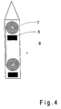
- An invasive instrument 9 is shown in FIG which several oscillating circuits, each consisting of an inductor 7 and a capacitor 8, on the side Surfaces of the instrument 9 are arranged.
- the inductance 7 is formed by a spiral conductor. This causes the induced magnetic field to be vertical Direction from the instrument 9 in the surrounding Tissue is directed. So it is in the outer close range the resonant circuit is strengthened the excitation.
- the inside of the MR image is then not of the instrument, but the environment of the instrument highlighted, but this also makes the position as easy of the instrument is to be identified.
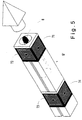
- Figure 5 shows an alternative embodiment of the instrument of Figure 4 in perspective, with can be seen that on each side of the square-shaped Instruments a spiral coil arrangement 71, 72, 73, 74 is provided, which together with a schematic capacitor 8 shown form a resonant circuit.
- the induced magnetic field is perpendicular to the longitudinal axis of the instrument 9 '. By the induced magnetic field occurs in the magnetic field lines penetrated an outer close range of the instrument enhanced excitation of the nuclear spins, so that this in the MR image Surrounding area highlighted and thus on the position of the instrument can be inferred.
- FIGS. 6a, 6b show an oscillating circle according to the invention formed on a dental implant 13, the Axes of the inductors 23a, 23b are again perpendicular (Fig. 6a) or parallel (Fig. 6b) to the longitudinal axis of the dental implant run.
- the capacitor 33a, 33b is by parallel annular conductor formed.
- 9a shows the dental implant with tooth 14 on and Fig. 9a with still free contact point 15.
- the inductors and capacitors can turn on be formed of a film which after sealing on the Dental implant 13 is applied. Alternatively, you can Inductance and / or capacitance also consist of wire or be cut from a sheet. In a preferred one
- the variant is the dental implant 13 as a composite material trained and inductance and / or capacitance in introduced the material of the dental implant. Hereby it is avoided that the inductive or capacitive elements arranged on the surface of the dental implant 13 are.
- a joint implant 16 is shown in each of FIGS. 7a, 7b shown with integrated resonant circuit. Construction and Arrangement of inductors 24a, 24b and capacitors 34a, 34b essentially correspond to that of FIGS. 9a, 9b.
- the capacitance 34a, 34b is in the form of two one above the other (alternatively: next to each other) Plates trained.
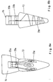
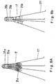
- an oscillating circuit is in each case at one Vena Cava Filter 17 trained.
- a vena cava filter will especially to protect against venous thrombosis as a kind Funnel inserted into a vein.
- the inductance 25a, 25b is again spiral (Fig. 8a) or helical (Fig. 8b).
- the capacitance 35a, 35b is, for example, again by parallel, ring-shaped capacitive elements.
- the inductors 25a, 25b are preferably used with a Laser cut from sheet metal. You are appropriately attached to the toothing elements 171 and additionally serve for stabilization.
- FIGS. 9a, 9b finally show a heart valve 18 with a ring 181 that is sewn into the heart tissue and on which the actual heart valve 182 is movably arranged is.
- the one increased excitation of nuclear spins is, on the one hand, in a capacitor 36a, 36b is integrated into the ring 181, for example in Form of parallel ring-shaped conductors.
- Fig. 9a are as Inductance solenoid coils 26a are provided, which are on Unfold the circumference of the ring.
- 9b is in the ring 181 in addition to the capacitor 36b as an inductance of the resonant circuit a ring coil 26b integrated.
- this is also used for flow measurement, insofar as they, such as the vena cava filter of FIG a fluid flows through or around.
- the device preferably has two arranged one behind the other Resonant circuits, with one resonant circuit being two crossed Has diodes according to Figure 2e, so that the capacitance when the excitation is short-circuited during the Resonant circuit is formed without diodes. This leads to, that when irradiating high-frequency MR excitation pulses in a portion of the device by the resonant circuit is surrounded without diodes, an increased excitation takes place.
- the Invention is provided that the inductance of the device also as a receiving coil for recording MR response signals is used, the inductance then via a cable connection with extracorporeal functional components connected is. This enables the inductance of the resonant circuit in addition to imaging to use. Because of the need for a cable connection with extracorporeal functional components however, this is generally only during an operative Procedures come into question.
- the invention is not limited in its execution the above-mentioned embodiments. Much more a number of variants are conceivable, which of the Invention also in fundamentally different types Make use.
Landscapes
- Health & Medical Sciences (AREA)
- Physics & Mathematics (AREA)
- Life Sciences & Earth Sciences (AREA)
- Engineering & Computer Science (AREA)
- General Health & Medical Sciences (AREA)
- Pathology (AREA)
- General Physics & Mathematics (AREA)
- Biomedical Technology (AREA)
- Condensed Matter Physics & Semiconductors (AREA)
- Veterinary Medicine (AREA)
- Public Health (AREA)
- Animal Behavior & Ethology (AREA)
- Heart & Thoracic Surgery (AREA)
- Vascular Medicine (AREA)
- Biophysics (AREA)
- Medical Informatics (AREA)
- Molecular Biology (AREA)
- Surgery (AREA)
- Transplantation (AREA)
- Oral & Maxillofacial Surgery (AREA)
- Cardiology (AREA)
- Immunology (AREA)
- Human Computer Interaction (AREA)
- Magnetic Resonance Imaging Apparatus (AREA)
- Media Introduction/Drainage Providing Device (AREA)
Applications Claiming Priority (3)
| Application Number | Priority Date | Filing Date | Title |
|---|---|---|---|
| DE19746735A DE19746735C2 (de) | 1997-10-13 | 1997-10-13 | NMR-Bildgebungsverfahren zur Darstellung, Positionsbestimmung oder funktionellen Kontrolle einer in ein Untersuchungsobjekt eingeführten Vorrichtung und Vorrichtung zur Verwendung in einem derartigen Verfahren |
| DE19746735 | 1997-10-13 | ||
| EP98958198A EP1021730B1 (fr) | 1997-10-13 | 1998-10-13 | Système d'imagerie par résonance magnétique et filtre à veine cave pour ce système |
Related Parent Applications (1)
| Application Number | Title | Priority Date | Filing Date |
|---|---|---|---|
| EP98958198A Division EP1021730B1 (fr) | 1997-10-13 | 1998-10-13 | Système d'imagerie par résonance magnétique et filtre à veine cave pour ce système |
Publications (2)
| Publication Number | Publication Date |
|---|---|
| EP1092985A2 true EP1092985A2 (fr) | 2001-04-18 |
| EP1092985A3 EP1092985A3 (fr) | 2001-06-27 |
Family
ID=7846328
Family Applications (3)
| Application Number | Title | Priority Date | Filing Date |
|---|---|---|---|
| EP98958198A Expired - Lifetime EP1021730B1 (fr) | 1997-10-13 | 1998-10-13 | Système d'imagerie par résonance magnétique et filtre à veine cave pour ce système |
| EP98956813A Expired - Lifetime EP1023609B1 (fr) | 1997-10-13 | 1998-10-13 | Extenseur et procede d'imagerie par resonance magnetique pour representer et determiner la position d'un extenseur |
| EP00250427A Withdrawn EP1092985A3 (fr) | 1997-10-13 | 1998-10-13 | Méthode d'imagerie à résonance magnétique et appareil médical appliqué |
Family Applications Before (2)
| Application Number | Title | Priority Date | Filing Date |
|---|---|---|---|
| EP98958198A Expired - Lifetime EP1021730B1 (fr) | 1997-10-13 | 1998-10-13 | Système d'imagerie par résonance magnétique et filtre à veine cave pour ce système |
| EP98956813A Expired - Lifetime EP1023609B1 (fr) | 1997-10-13 | 1998-10-13 | Extenseur et procede d'imagerie par resonance magnetique pour representer et determiner la position d'un extenseur |
Country Status (8)
| Country | Link |
|---|---|
| US (2) | US6280385B1 (fr) |
| EP (3) | EP1021730B1 (fr) |
| JP (2) | JP4309043B2 (fr) |
| AU (2) | AU1432999A (fr) |
| CA (2) | CA2306124C (fr) |
| DE (3) | DE19746735C2 (fr) |
| ES (2) | ES2196626T3 (fr) |
| WO (2) | WO1999019738A1 (fr) |
Cited By (3)
| Publication number | Priority date | Publication date | Assignee | Title |
|---|---|---|---|---|
| WO2004015438A1 (fr) * | 2002-08-12 | 2004-02-19 | Scimed Life Systems, Inc. | Dispositif intravasculaire de rehaussement de signal irm comprenant un condensateur ajustable |
| WO2004053512A1 (fr) * | 2002-12-12 | 2004-06-24 | Amris Patente Gmbh | Filtre vasculaire pour procede d'imagerie par resonance magnetique |
| WO2007031316A1 (fr) * | 2005-09-14 | 2007-03-22 | Biophan Europe Gmbh | Prothese valvulaire a compatibilite mrt a utiliser dans l'organisme humain ou animal pour remplacer une valvule d'organe ou de vaisseau |
Families Citing this family (209)
| Publication number | Priority date | Publication date | Assignee | Title |
|---|---|---|---|---|
| DE19746735C2 (de) * | 1997-10-13 | 2003-11-06 | Simag Gmbh Systeme Und Instr F | NMR-Bildgebungsverfahren zur Darstellung, Positionsbestimmung oder funktionellen Kontrolle einer in ein Untersuchungsobjekt eingeführten Vorrichtung und Vorrichtung zur Verwendung in einem derartigen Verfahren |
| DE19800471A1 (de) * | 1998-01-09 | 1999-07-15 | Philips Patentverwaltung | MR-Verfahren mit im Untersuchungsbereich befindlichen Mikrospulen |
| DE19844767C2 (de) * | 1998-09-29 | 2002-11-21 | Simag Gmbh Systeme Und Instr F | Betriebsverfahren für ein Kernspintomographiegerät zur Ermittlung der Position eines Instruments und zur Durchführung des Verfahrens |
| US6701176B1 (en) | 1998-11-04 | 2004-03-02 | Johns Hopkins University School Of Medicine | Magnetic-resonance-guided imaging, electrophysiology, and ablation |
| US8244370B2 (en) * | 2001-04-13 | 2012-08-14 | Greatbatch Ltd. | Band stop filter employing a capacitor and an inductor tank circuit to enhance MRI compatibility of active medical devices |
| US9061139B2 (en) | 1998-11-04 | 2015-06-23 | Greatbatch Ltd. | Implantable lead with a band stop filter having a capacitor in parallel with an inductor embedded in a dielectric body |
| DE19921088C2 (de) * | 1999-04-30 | 2003-08-07 | Magforce Applic Gmbh | Stent zur Offenhaltung gangartiger Strukturen |
| DE19956595A1 (de) * | 1999-11-25 | 2001-05-31 | Philips Corp Intellectual Pty | MR-Verfahren zur Anregung der Kernmagnetisierung in einem begrenzten räumlichen Bereich |
| EP1132048B1 (fr) * | 2000-03-06 | 2004-12-29 | Medos SA | Spectrométre implantable à résonance magnétique nucléaire |
| US6487437B1 (en) * | 2000-03-21 | 2002-11-26 | Image-Guided Neurologies, Inc. | Device for high gain and uniformly localized magnetic resonance imaging |
| WO2001075466A1 (fr) * | 2000-03-30 | 2001-10-11 | Case Western Reserve University | Desaccord sans fil dans un milieu de resonance magnetique |
| DE10055686A1 (de) * | 2000-11-03 | 2002-05-08 | Biotronik Mess & Therapieg | Vorrichtung zur Beeinflussung von Zellproliferationsmechanismen in Gefäßen des menschlichen oder tierischen Körpers |
| US8372139B2 (en) * | 2001-02-14 | 2013-02-12 | Advanced Bio Prosthetic Surfaces, Ltd. | In vivo sensor and method of making same |
| US6574497B1 (en) | 2000-12-22 | 2003-06-03 | Advanced Cardiovascular Systems, Inc. | MRI medical device markers utilizing fluorine-19 |
| US6767360B1 (en) * | 2001-02-08 | 2004-07-27 | Inflow Dynamics Inc. | Vascular stent with composite structure for magnetic reasonance imaging capabilities |
| US20070168006A1 (en) * | 2001-02-20 | 2007-07-19 | Biophan Technologies, Inc. | Medical device with an electrically conductive anti-antenna member |
| US20070173911A1 (en) * | 2001-02-20 | 2007-07-26 | Biophan Technologies, Inc. | Medical device with an electrically conductive anti-antenna member |
| US20070168005A1 (en) * | 2001-02-20 | 2007-07-19 | Biophan Technologies, Inc. | Medical device with an electrically conductive anti-antenna member |
| US20050288753A1 (en) * | 2003-08-25 | 2005-12-29 | Biophan Technologies, Inc. | Medical device with an electrically conductive anti-antenna member |
| US6949929B2 (en) * | 2003-06-24 | 2005-09-27 | Biophan Technologies, Inc. | Magnetic resonance imaging interference immune device |
| US20050288750A1 (en) * | 2003-08-25 | 2005-12-29 | Biophan Technologies, Inc. | Medical device with an electrically conductive anti-antenna member |
| US20050283214A1 (en) * | 2003-08-25 | 2005-12-22 | Biophan Technologies, Inc. | Medical device with an electrically conductive anti-antenna member |
| US20050283167A1 (en) * | 2003-08-25 | 2005-12-22 | Biophan Technologies, Inc. | Medical device with an electrically conductive anti-antenna member |
| US6829509B1 (en) * | 2001-02-20 | 2004-12-07 | Biophan Technologies, Inc. | Electromagnetic interference immune tissue invasive system |
| US8219208B2 (en) | 2001-04-13 | 2012-07-10 | Greatbatch Ltd. | Frequency selective passive component networks for active implantable medical devices utilizing an energy dissipating surface |
| US8509913B2 (en) * | 2001-04-13 | 2013-08-13 | Greatbatch Ltd. | Switched diverter circuits for minimizing heating of an implanted lead and/or providing EMI protection in a high power electromagnetic field environment |
| WO2002083016A1 (fr) | 2001-04-13 | 2002-10-24 | Surgi-Vision, Inc. | Systemes et procedes d'interventions guidees par resonance magnetique |
| US7899551B2 (en) * | 2001-04-13 | 2011-03-01 | Greatbatch Ltd. | Medical lead system utilizing electromagnetic bandstop filters |
| US9295828B2 (en) | 2001-04-13 | 2016-03-29 | Greatbatch Ltd. | Self-resonant inductor wound portion of an implantable lead for enhanced MRI compatibility of active implantable medical devices |
| US7787958B2 (en) | 2001-04-13 | 2010-08-31 | Greatbatch Ltd. | RFID detection and identification system for implantable medical lead systems |
| US8712544B2 (en) | 2001-04-13 | 2014-04-29 | Greatbatch Ltd. | Electromagnetic shield for a passive electronic component in an active medical device implantable lead |
| US8457760B2 (en) | 2001-04-13 | 2013-06-04 | Greatbatch Ltd. | Switched diverter circuits for minimizing heating of an implanted lead and/or providing EMI protection in a high power electromagnetic field environment |
| US8989870B2 (en) | 2001-04-13 | 2015-03-24 | Greatbatch Ltd. | Tuned energy balanced system for minimizing heating and/or to provide EMI protection of implanted leads in a high power electromagnetic field environment |
| US7853325B2 (en) * | 2001-04-13 | 2010-12-14 | Greatbatch Ltd. | Cylindrical bandstop filters for medical lead systems |
| US8977355B2 (en) | 2001-04-13 | 2015-03-10 | Greatbatch Ltd. | EMI filter employing a capacitor and an inductor tank circuit having optimum component values |
| US20070088416A1 (en) * | 2001-04-13 | 2007-04-19 | Surgi-Vision, Inc. | Mri compatible medical leads |
| US6712844B2 (en) | 2001-06-06 | 2004-03-30 | Advanced Cardiovascular Systems, Inc. | MRI compatible stent |
| DE10127850B4 (de) * | 2001-06-08 | 2006-04-13 | Lars Dr.med. Grenacher | Vorrichtung zum Durchführen Kernresonanzspektroskopischer Untersuchungen im Inneren organischer Körper |
| AU2002345328A1 (en) | 2001-06-27 | 2003-03-03 | Remon Medical Technologies Ltd. | Method and device for electrochemical formation of therapeutic species in vivo |
| US6702847B2 (en) * | 2001-06-29 | 2004-03-09 | Scimed Life Systems, Inc. | Endoluminal device with indicator member for remote detection of endoleaks and/or changes in device morphology |
| FR2826760B1 (fr) * | 2001-06-29 | 2004-01-09 | Ge Med Sys Global Tech Co Llc | Procede de visualisation du deploiement d'une prothese endo-vasculaire |
| WO2003015662A1 (fr) | 2001-08-08 | 2003-02-27 | Buecker Arno | Endoprothese metallique compatible avec la resonance magnetique |
| DE10151779A1 (de) * | 2001-10-19 | 2003-05-08 | Philips Corp Intellectual Pty | Verfahren zum Lokalisieren eines Gegenstandes in einer MR-Apparatur sowie Katheter und MR-Apparatur zur Durchführung des Verfahrens |
| US20050178584A1 (en) * | 2002-01-22 | 2005-08-18 | Xingwu Wang | Coated stent and MR imaging thereof |
| DE10203371A1 (de) * | 2002-01-29 | 2003-08-07 | Siemens Ag | Katheter, insbesondere intravaskulärer Katheter |
| DE10203372A1 (de) * | 2002-01-29 | 2003-09-04 | Siemens Ag | Medizinisches Untersuchungs- und/oder Behandlungssystem |
| GB0206061D0 (en) * | 2002-03-14 | 2002-04-24 | Angiomed Ag | Metal structure compatible with MRI imaging, and method of manufacturing such a structure |
| US6904307B2 (en) | 2002-05-29 | 2005-06-07 | Surgi-Vision, Inc. | Magnetic resonance probes |
| US7331986B2 (en) * | 2002-10-09 | 2008-02-19 | Boston Scientific Scimed, Inc. | Intraluminal medical device having improved visibility |
| JP2006509571A (ja) * | 2002-12-13 | 2006-03-23 | コーニンクレッカ フィリップス エレクトロニクス エヌ ヴィ | 磁気共鳴装置内の対象の位置を決定する装置及び方法 |
| EP1594420A2 (fr) * | 2003-01-31 | 2005-11-16 | Koninklijke Philips Electronics N.V. | Stent compatible avec la resonance magnetique |
| US7172624B2 (en) * | 2003-02-06 | 2007-02-06 | Boston Scientific Scimed, Inc. | Medical device with magnetic resonance visibility enhancing structure |
| US7792568B2 (en) * | 2003-03-17 | 2010-09-07 | Boston Scientific Scimed, Inc. | MRI-visible medical devices |
| DE10321119A1 (de) * | 2003-05-09 | 2004-11-25 | Phytis Medical Devices Gmbh | Marker zur Kennzeichnung von funktionellen Stellen bei Implantaten |
| US20040230290A1 (en) * | 2003-05-15 | 2004-11-18 | Jan Weber | Medical devices and methods of making the same |
| US7839146B2 (en) * | 2003-06-24 | 2010-11-23 | Medtronic, Inc. | Magnetic resonance imaging interference immune device |
| US7388378B2 (en) * | 2003-06-24 | 2008-06-17 | Medtronic, Inc. | Magnetic resonance imaging interference immune device |
| US7479157B2 (en) * | 2003-08-07 | 2009-01-20 | Boston Scientific Scimed, Inc. | Stent designs which enable the visibility of the inside of the stent during MRI |
| US20050038497A1 (en) * | 2003-08-11 | 2005-02-17 | Scimed Life Systems, Inc. | Deformation medical device without material deformation |
| US8721710B2 (en) * | 2003-08-11 | 2014-05-13 | Hdh Medical Ltd. | Anastomosis system and method |
| US20050043786A1 (en) * | 2003-08-18 | 2005-02-24 | Medtronic Ave, Inc. | Methods and apparatus for treatment of aneurysmal tissue |
| US20050050042A1 (en) * | 2003-08-20 | 2005-03-03 | Marvin Elder | Natural language database querying |
| US20050288754A1 (en) * | 2003-08-25 | 2005-12-29 | Biophan Technologies, Inc. | Medical device with an electrically conductive anti-antenna member |
| US8868212B2 (en) * | 2003-08-25 | 2014-10-21 | Medtronic, Inc. | Medical device with an electrically conductive anti-antenna member |
| US20050049689A1 (en) * | 2003-08-25 | 2005-03-03 | Biophan Technologies, Inc. | Electromagnetic radiation transparent device and method of making thereof |
| US20050288752A1 (en) * | 2003-08-25 | 2005-12-29 | Biophan Technologies, Inc. | Medical device with an electrically conductive anti-antenna member |
| US20050288756A1 (en) * | 2003-08-25 | 2005-12-29 | Biophan Technologies, Inc. | Medical device with an electrically conductive anti-antenna member |
| US20050288751A1 (en) * | 2003-08-25 | 2005-12-29 | Biophan Technologies, Inc. | Medical device with an electrically conductive anti-antenna member |
| US20050283213A1 (en) * | 2003-08-25 | 2005-12-22 | Biophan Technologies, Inc. | Medical device with an electrically conductive anti-antenna member |
| US20050288755A1 (en) * | 2003-08-25 | 2005-12-29 | Biophan Technologies, Inc. | Medical device with an electrically conductive anti-antenna member |
| JP4838131B2 (ja) * | 2003-09-09 | 2011-12-14 | コーニンクレッカ フィリップス エレクトロニクス エヌ ヴィ | 磁気共鳴イメージングによりモニタされるインターベンショナル処置用のカテーテル先端部のトラッキング |
| JP4846582B2 (ja) * | 2003-09-12 | 2011-12-28 | コーニンクレッカ フィリップス エレクトロニクス エヌ ヴィ | マイクロコイルを備える医療機器の位置を突きとめるための方法 |
| US20050065437A1 (en) * | 2003-09-24 | 2005-03-24 | Scimed Life Systems, Inc. | Medical device with markers for magnetic resonance visibility |
| US20050085895A1 (en) * | 2003-10-15 | 2005-04-21 | Scimed Life Systems, Inc. | RF-based markers for MRI visualization of medical devices |
| US7367970B2 (en) * | 2003-11-11 | 2008-05-06 | Biosense Webster Inc. | Externally applied RF for pulmonary vein isolation |
| DE10355986A1 (de) * | 2003-11-27 | 2005-06-30 | Forschungszentrum Karlsruhe Gmbh | Kompressionsmanschette |
| DE10357334A1 (de) * | 2003-12-05 | 2005-07-07 | Grönemeyer, Dietrich H. W., Prof. Dr.med. | MR-kompatibles medizinisches Implantat |
| WO2005057232A1 (fr) * | 2003-12-08 | 2005-06-23 | Philips Intellectual Property & Standards Gmbh | Agencement de circuits destine a desaccorder un circuit resonant d'un appareil a resonance magnetique |
| GB0400571D0 (en) * | 2004-01-12 | 2004-02-11 | Angiomed Gmbh & Co | Implant |
| US8620406B2 (en) * | 2004-01-23 | 2013-12-31 | Boston Scientific Scimed, Inc. | Medical devices visible by magnetic resonance imaging |
| BE1015916A3 (nl) * | 2004-02-25 | 2005-11-08 | Clerck Rene De | Werkwijze en markeerelement voor het bepalen van de positie van een dentaal implantaat. |
| US7761138B2 (en) * | 2004-03-12 | 2010-07-20 | Boston Scientific Scimed, Inc. | MRI and X-ray visualization |
| US7483732B2 (en) * | 2004-04-15 | 2009-01-27 | Boston Scientific Scimed, Inc. | Magnetic resonance imaging of a medical device and proximate body tissue |
| EP1743186B1 (fr) | 2004-04-23 | 2017-07-26 | Koninklijke Philips N.V. | Système d'imagerie par résonance magnétique pourvu d'un dispositif électrique accessoire |
| US20050278017A1 (en) * | 2004-06-09 | 2005-12-15 | Scimed Life Systems, Inc. | Overlapped stents for scaffolding, flexibility and MRI compatibility |
| US7750637B2 (en) | 2004-06-28 | 2010-07-06 | Koninklijke Philips Electronics N.V. | Transmission line for use in RF fields |
| WO2006023700A2 (fr) * | 2004-08-20 | 2006-03-02 | Biophan Technologies, Inc. | Dispositif d'imagerie par resonance magnetique insensible aux interferences |
| US8060183B2 (en) * | 2004-10-13 | 2011-11-15 | Suros Surgical Systems, Inc. | Site marker visible under multiple modalities |
| US8280486B2 (en) | 2004-10-13 | 2012-10-02 | Suros Surgical Systems, Inc. | Site marker visable under multiple modalities |
| US8442623B2 (en) * | 2004-10-13 | 2013-05-14 | Suros Surgical Systems, Inc. | Site marker visible under multiple modalities |
| US20060079805A1 (en) * | 2004-10-13 | 2006-04-13 | Miller Michael E | Site marker visable under multiple modalities |
| US20060105016A1 (en) * | 2004-11-12 | 2006-05-18 | Gray Robert W | Device compatible with magnetic resonance imaging |
| US8048141B2 (en) * | 2004-12-07 | 2011-11-01 | Boston Scientific Scimed, Inc. | Medical device that signals lumen loss |
| US20070244388A1 (en) * | 2004-12-17 | 2007-10-18 | Ryoji Sato | Position Detection System, Guidance System, Position Detection Method, Medical Device, and Medical Magnetic-Induction and Position-Detection System |
| EP3141921B1 (fr) | 2004-12-20 | 2019-02-20 | Koninklijke Philips N.V. | Voie de transmission destinee a des champs rf |
| DE102004062269A1 (de) * | 2004-12-23 | 2006-07-13 | Siemens Ag | Verfahren und Vorrichtung zum sicheren Betrieb eines Schaltgerätes |
| EP1681017A1 (fr) * | 2005-01-13 | 2006-07-19 | DKFZ Deutsches Krebsforschungszentrum | Chambre implantable, procédé d'imagerie et dispositif d'imagerie par résonance magnétique |
| US8066759B2 (en) * | 2005-02-04 | 2011-11-29 | Boston Scientific Scimed, Inc. | Resonator for medical device |
| EP2570385A3 (fr) * | 2005-05-03 | 2013-10-16 | Nanocomp Technologies, Inc. | Matériaux en composites de carbone et leurs procédés de fabrication |
| US20080286546A1 (en) * | 2005-05-03 | 2008-11-20 | Nanocomp Technologies, Inc. | Continuous glassy carbon composite materials reinforced with carbon nanotubes and methods of manufacturing same |
| WO2006125086A2 (fr) * | 2005-05-19 | 2006-11-23 | Isoflux, Inc. | Systeme et procede d'enrobage multicouche |
| US20070010740A1 (en) * | 2005-05-19 | 2007-01-11 | Biophan Technologies, Inc. | Electromagnetic resonant circuit sleeve for implantable medical device |
| US20060265049A1 (en) * | 2005-05-19 | 2006-11-23 | Gray Robert W | Stent and MR imaging process and device |
| US7595469B2 (en) * | 2005-05-24 | 2009-09-29 | Boston Scientific Scimed, Inc. | Resonator for medical device |
| US7279664B2 (en) * | 2005-07-26 | 2007-10-09 | Boston Scientific Scimed, Inc. | Resonator for medical device |
| DE102005034838B4 (de) | 2005-07-26 | 2018-03-29 | Karsten König | Vorrichtung zur NMR-Untersuchung intrakorporaler Köperbereiche |
| US7778684B2 (en) * | 2005-08-08 | 2010-08-17 | Boston Scientific Scimed, Inc. | MRI resonator system with stent implant |
| JP4763439B2 (ja) * | 2005-08-08 | 2011-08-31 | オリンパス株式会社 | 医療装置磁気誘導・位置検出システム |
| US7304277B2 (en) * | 2005-08-23 | 2007-12-04 | Boston Scientific Scimed, Inc | Resonator with adjustable capacitor for medical device |
| US7524282B2 (en) * | 2005-08-29 | 2009-04-28 | Boston Scientific Scimed, Inc. | Cardiac sleeve apparatus, system and method of use |
| DE102005047235A1 (de) | 2005-10-01 | 2007-04-05 | Grönemeyer, Dietrich H. W., Prof. Dr.med. | MR-kompatible Gefäßendoprothese |
| US7423496B2 (en) | 2005-11-09 | 2008-09-09 | Boston Scientific Scimed, Inc. | Resonator with adjustable capacitance for medical device |
| US7853324B2 (en) * | 2005-11-11 | 2010-12-14 | Greatbatch Ltd. | Tank filters utilizing very low K materials, in series with lead wires or circuits of active medical devices to enhance MRI compatibility |
| US8224462B2 (en) | 2005-11-11 | 2012-07-17 | Greatbatch Ltd. | Medical lead system utilizing electromagnetic bandstop filters |
| EP1945297B1 (fr) * | 2005-11-11 | 2016-08-10 | Greatbatch Ltd. | Filtres tank montés en série avec les fils conducteurs ou les circuits de dispositifs médicaux actifs, et en améliorant la compatibilité avec l'irm |
| JP4757021B2 (ja) * | 2005-12-28 | 2011-08-24 | オリンパス株式会社 | 位置検出システム |
| US8840660B2 (en) * | 2006-01-05 | 2014-09-23 | Boston Scientific Scimed, Inc. | Bioerodible endoprostheses and methods of making the same |
| US8089029B2 (en) | 2006-02-01 | 2012-01-03 | Boston Scientific Scimed, Inc. | Bioabsorbable metal medical device and method of manufacture |
| US20070239256A1 (en) * | 2006-03-22 | 2007-10-11 | Jan Weber | Medical devices having electrical circuits with multilayer regions |
| US20070224244A1 (en) * | 2006-03-22 | 2007-09-27 | Jan Weber | Corrosion resistant coatings for biodegradable metallic implants |
| US8048150B2 (en) | 2006-04-12 | 2011-11-01 | Boston Scientific Scimed, Inc. | Endoprosthesis having a fiber meshwork disposed thereon |
| DE102006036649A1 (de) | 2006-04-27 | 2007-10-31 | Biophan Europe Gmbh | Okkluder |
| WO2007140389A2 (fr) * | 2006-05-30 | 2007-12-06 | Biophan Technologies, Inc. | stent d'imagerie À rÉsonance magnÉtique prÉsentant une compatibilitÉ inter-luminale avec L'imagerie À rÉsonance magnÉtique |
| US8903505B2 (en) | 2006-06-08 | 2014-12-02 | Greatbatch Ltd. | Implantable lead bandstop filter employing an inductive coil with parasitic capacitance to enhance MRI compatibility of active medical devices |
| US7702387B2 (en) | 2006-06-08 | 2010-04-20 | Greatbatch Ltd. | Tank filters adaptable for placement with a guide wire, in series with the lead wires or circuits of active medical devices to enhance MRI compatibility |
| US9042999B2 (en) * | 2006-06-08 | 2015-05-26 | Greatbatch Ltd. | Low loss band pass filter for RF distance telemetry pin antennas of active implantable medical devices |
| US8116862B2 (en) * | 2006-06-08 | 2012-02-14 | Greatbatch Ltd. | Tank filters placed in series with the lead wires or circuits of active medical devices to enhance MRI compatibility |
| EP2054537A2 (fr) | 2006-08-02 | 2009-05-06 | Boston Scientific Scimed, Inc. | Endoprothèse avec contrôle tridimensionnel de désintégration |
| US8414637B2 (en) * | 2006-09-08 | 2013-04-09 | Boston Scientific Scimed, Inc. | Stent |
| JP2010503490A (ja) | 2006-09-15 | 2010-02-04 | ボストン サイエンティフィック リミテッド | 調整可能な表面特徴を備えた内部人工器官 |
| EP2959925B1 (fr) | 2006-09-15 | 2018-08-29 | Boston Scientific Limited | Dispositifs médicaux et procédés de réalisation desdits dispositifs |
| JP2010503494A (ja) | 2006-09-15 | 2010-02-04 | ボストン サイエンティフィック リミテッド | 生分解性内部人工器官およびその製造方法 |
| CA2663250A1 (fr) | 2006-09-15 | 2008-03-20 | Boston Scientific Limited | Endoprotheses biodegradables et procedes de fabrication |
| EP2121068B1 (fr) | 2006-09-15 | 2010-12-08 | Boston Scientific Scimed, Inc. | Endoprothèse bioérodable à couches inorganiques biostables |
| US8002821B2 (en) | 2006-09-18 | 2011-08-23 | Boston Scientific Scimed, Inc. | Bioerodible metallic ENDOPROSTHESES |
| JP2010503486A (ja) * | 2006-09-18 | 2010-02-04 | ボストン サイエンティフィック リミテッド | 内部人工器官 |
| US20080097577A1 (en) * | 2006-10-20 | 2008-04-24 | Boston Scientific Scimed, Inc. | Medical device hydrogen surface treatment by electrochemical reduction |
| US9468750B2 (en) | 2006-11-09 | 2016-10-18 | Greatbatch Ltd. | Multilayer planar spiral inductor filter for medical therapeutic or diagnostic applications |
| US9031670B2 (en) | 2006-11-09 | 2015-05-12 | Greatbatch Ltd. | Electromagnetic shield for a passive electronic component in an active medical device implantable lead |
| US20080140180A1 (en) * | 2006-12-07 | 2008-06-12 | Medtronic Vascular, Inc. | Vascular Position Locating Apparatus and Method |
| US20080139915A1 (en) * | 2006-12-07 | 2008-06-12 | Medtronic Vascular, Inc. | Vascular Position Locating and/or Mapping Apparatus and Methods |
| US8768486B2 (en) | 2006-12-11 | 2014-07-01 | Medtronic, Inc. | Medical leads with frequency independent magnetic resonance imaging protection |
| US20080147173A1 (en) * | 2006-12-18 | 2008-06-19 | Medtronic Vascular, Inc. | Prosthesis Deployment Apparatus and Methods |
| CA2674195A1 (fr) * | 2006-12-28 | 2008-07-10 | Boston Scientific Limited | Endoprotheses bio-erodables et procedes de fabrication de celles-ci |
| US8473030B2 (en) * | 2007-01-12 | 2013-06-25 | Medtronic Vascular, Inc. | Vessel position and configuration imaging apparatus and methods |
| US20080172119A1 (en) * | 2007-01-12 | 2008-07-17 | Medtronic Vascular, Inc. | Prosthesis Deployment Apparatus and Methods |
| US20080188921A1 (en) * | 2007-02-02 | 2008-08-07 | Medtronic Vascular, Inc. | Prosthesis Deployment Apparatus and Methods |
| JP5693952B2 (ja) * | 2007-04-27 | 2015-04-01 | コーニンクレッカ フィリップス エヌ ヴェ | 安全モードを有するアンテナシステム |
| US20080272776A1 (en) * | 2007-05-03 | 2008-11-06 | Edelman Robert R | Magnetic resonance image acquisition with suppression of background tissues and rf water excitation at offset frequency |
| US20100201361A1 (en) * | 2007-05-03 | 2010-08-12 | Edelman Robert R | System and method for passive catheter tracking with magnetic resonance imaging |
| DE102007021692A1 (de) * | 2007-05-09 | 2008-11-13 | Biotronik Vi Patent Ag | Medizinisches Implantat, insbesondere Stent zum Einsatz in Körperlumen |
| US7810223B2 (en) * | 2007-05-16 | 2010-10-12 | Boston Scientific Scimed, Inc. | Method of attaching radiopaque markers to intraluminal medical devices, and devices formed using the same |
| JP5269348B2 (ja) * | 2007-05-21 | 2013-08-21 | オリンパス株式会社 | 位置検出システム及び位置検出システムの作動方法 |
| US8052745B2 (en) | 2007-09-13 | 2011-11-08 | Boston Scientific Scimed, Inc. | Endoprosthesis |
| US20090143855A1 (en) * | 2007-11-29 | 2009-06-04 | Boston Scientific Scimed, Inc. | Medical Device Including Drug-Loaded Fibers |
| US20100008970A1 (en) * | 2007-12-14 | 2010-01-14 | Boston Scientific Scimed, Inc. | Drug-Eluting Endoprosthesis |
| US20090179716A1 (en) * | 2008-01-09 | 2009-07-16 | Anaren, Inc. | RF Filter Device |
| US9095685B2 (en) * | 2008-01-23 | 2015-08-04 | Mediguide Ltd. | Sensor mounted flexible guidewire |
| IL196660A (en) | 2008-01-23 | 2014-09-30 | Mediguide Ltd | Flexible conductive catheter with sensor |
| DE102008010190A1 (de) * | 2008-02-20 | 2009-09-03 | Piazolo, Pius, Dipl.-Ing. | Elektrisches Stromerzeugungselement |
| US10080889B2 (en) | 2009-03-19 | 2018-09-25 | Greatbatch Ltd. | Low inductance and low resistance hermetically sealed filtered feedthrough for an AIMD |
| US9108066B2 (en) | 2008-03-20 | 2015-08-18 | Greatbatch Ltd. | Low impedance oxide resistant grounded capacitor for an AIMD |
| US20090259284A1 (en) * | 2008-04-10 | 2009-10-15 | Medtronic Vascular, Inc. | Resonating Stent or Stent Element |
| US20090259296A1 (en) * | 2008-04-10 | 2009-10-15 | Medtronic Vascular, Inc. | Gate Cannulation Apparatus and Methods |
| US7998192B2 (en) | 2008-05-09 | 2011-08-16 | Boston Scientific Scimed, Inc. | Endoprostheses |
| US8236046B2 (en) | 2008-06-10 | 2012-08-07 | Boston Scientific Scimed, Inc. | Bioerodible endoprosthesis |
| US7985252B2 (en) * | 2008-07-30 | 2011-07-26 | Boston Scientific Scimed, Inc. | Bioerodible endoprosthesis |
| WO2010014510A1 (fr) * | 2008-07-31 | 2010-02-04 | Boston Scientific Scimed, Inc. | Bobines pour des implants vasculaires, ou d'autres utilisations |
| US20110130647A1 (en) * | 2008-07-31 | 2011-06-02 | The Trustees of Dartmouth College noneprofit corporation | System And Method Using Coupler-Resonators For Electron Paramagnetic Resonance Spectroscopy |
| US8382824B2 (en) * | 2008-10-03 | 2013-02-26 | Boston Scientific Scimed, Inc. | Medical implant having NANO-crystal grains with barrier layers of metal nitrides or fluorides |
| EP2349453A4 (fr) | 2008-10-30 | 2015-07-01 | Greatbatch Ltd | Eléments condensateurs et inducteurs physiquement disposés en série dont les paramètres localisés sont électriquement connectés en parallèle pour former un filtre à élimination de bande |
| US8644951B1 (en) | 2009-12-02 | 2014-02-04 | University Of Central Florida Research Foundation, Inc. | Medical devices having MRI compatible metal alloys |
| US8447414B2 (en) * | 2008-12-17 | 2013-05-21 | Greatbatch Ltd. | Switched safety protection circuit for an AIMD system during exposure to high power electromagnetic fields |
| CN101782635A (zh) * | 2009-01-20 | 2010-07-21 | 西门子迈迪特(深圳)磁共振有限公司 | 磁共振信号的接收器和接收方法 |
| US8267992B2 (en) | 2009-03-02 | 2012-09-18 | Boston Scientific Scimed, Inc. | Self-buffering medical implants |
| US9259290B2 (en) | 2009-06-08 | 2016-02-16 | MRI Interventions, Inc. | MRI-guided surgical systems with proximity alerts |
| DE102009026897A1 (de) * | 2009-06-10 | 2010-12-16 | Sirona Dental Systems Gmbh | Sensor sowie Magnetfeldeinheit zur Verwendung innerhalb eines Magnetresonanztomographie-Systems oder eines Magnetresonanzspektroskopie-Systems |
| WO2010148083A2 (fr) | 2009-06-16 | 2010-12-23 | Surgivision, Inc. | Dispositifs guidés par irm et systèmes d'intervention guidés par irm qui peuvent suivre et générer des visualisations dynamiques des dispositifs presque en temps réel |
| US20110022158A1 (en) * | 2009-07-22 | 2011-01-27 | Boston Scientific Scimed, Inc. | Bioerodible Medical Implants |
| US20110022160A1 (en) * | 2009-07-24 | 2011-01-27 | Boston Scientific Scimed, Inc. | Medical Devices Having an Inorganic Coating Layer Formed by Atomic Layer Deposition |
| DE102009050532A1 (de) | 2009-10-23 | 2011-04-28 | Rheinisch-Westfälische Technische Hochschule Aachen | Positionsbestimmungsvorrichtung |
| US8983574B2 (en) | 2009-11-17 | 2015-03-17 | The Brigham And Women's Hospital | Catheter device with local magnetic resonance imaging coil and methods for use thereof |
| WO2011119573A1 (fr) * | 2010-03-23 | 2011-09-29 | Boston Scientific Scimed, Inc. | Endoprothèses en métal bioérodable traitées en surface |
| US9931514B2 (en) | 2013-06-30 | 2018-04-03 | Greatbatch Ltd. | Low impedance oxide resistant grounded capacitor for an AIMD |
| US10350421B2 (en) | 2013-06-30 | 2019-07-16 | Greatbatch Ltd. | Metallurgically bonded gold pocket pad for grounding an EMI filter to a hermetic terminal for an active implantable medical device |
| US10596369B2 (en) | 2011-03-01 | 2020-03-24 | Greatbatch Ltd. | Low equivalent series resistance RF filter for an active implantable medical device |
| US10272252B2 (en) | 2016-11-08 | 2019-04-30 | Greatbatch Ltd. | Hermetic terminal for an AIMD having a composite brazed conductive lead |
| US9427596B2 (en) | 2013-01-16 | 2016-08-30 | Greatbatch Ltd. | Low impedance oxide resistant grounded capacitor for an AIMD |
| US11198014B2 (en) | 2011-03-01 | 2021-12-14 | Greatbatch Ltd. | Hermetically sealed filtered feedthrough assembly having a capacitor with an oxide resistant electrical connection to an active implantable medical device housing |
| WO2012119037A1 (fr) | 2011-03-03 | 2012-09-07 | Boston Scientific Scimed, Inc. | Endoprothèse ayant un profil réduit |
| EP2680797B1 (fr) | 2011-03-03 | 2016-10-26 | Boston Scientific Scimed, Inc. | Stent à haute résistance et à faible contrainte |
| EP2549284A1 (fr) * | 2011-07-21 | 2013-01-23 | Koninklijke Philips Electronics N.V. | Marqueur de position pour une utilisation avec un appareil d'IRM |
| KR101286055B1 (ko) | 2011-11-02 | 2013-07-18 | 연세대학교 산학협력단 | 이미지 제공 시스템 및 방법 |
| USRE46699E1 (en) | 2013-01-16 | 2018-02-06 | Greatbatch Ltd. | Low impedance oxide resistant grounded capacitor for an AIMD |
| US10274557B2 (en) | 2013-03-14 | 2019-04-30 | Hilmi Volkan Demir | Enhancement of magnetic resonance image resolution by using bio-compatible, passive resonator hardware |
| US9737259B2 (en) | 2013-03-27 | 2017-08-22 | Industry-Academic Cooperation Foundation, Yonsei University | System and method for determining neointima thickness of a blood vessel |
| WO2017083498A1 (fr) * | 2015-11-11 | 2017-05-18 | University Of Utah Research Foundation | Bobine à ballonnet endoentérique |
| US10849521B2 (en) * | 2015-12-23 | 2020-12-01 | Biosense Webster (Israel) Ltd. | Multi-layered catheter shaft construction with embedded single axial sensors, and related methods |
| US11490975B2 (en) * | 2016-06-24 | 2022-11-08 | Versitech Limited | Robotic catheter system for MRI-guided cardiovascular interventions |
| US10249415B2 (en) | 2017-01-06 | 2019-04-02 | Greatbatch Ltd. | Process for manufacturing a leadless feedthrough for an active implantable medical device |
| DE102017122820A1 (de) * | 2017-09-29 | 2019-04-04 | Biotronik Ag | Implantat mit Sensoranordnung |
| CN111770726B (zh) * | 2018-03-09 | 2024-09-17 | 香港大学 | Mri跟踪装置的设计、制造以及用于mri引导机器人系统的使用方法 |
| US10912945B2 (en) | 2018-03-22 | 2021-02-09 | Greatbatch Ltd. | Hermetic terminal for an active implantable medical device having a feedthrough capacitor partially overhanging a ferrule for high effective capacitance area |
| US10905888B2 (en) | 2018-03-22 | 2021-02-02 | Greatbatch Ltd. | Electrical connection for an AIMD EMI filter utilizing an anisotropic conductive layer |
| EP3911273B1 (fr) | 2019-01-16 | 2025-01-15 | Half Moon Medical, Inc. | Dispositifs d'aide à la coaptation implantables avec capteurs et systèmes |
| EP4247302B1 (fr) | 2020-11-20 | 2026-02-18 | Medtronic, Inc. | Dispositifs de réparation de valve tricuspide |
| KR102433470B1 (ko) * | 2020-12-09 | 2022-08-18 | 한양대학교 산학협력단 | 혈관용 마이크로 코일 |
| EP4333776A1 (fr) * | 2021-05-05 | 2024-03-13 | Boston Scientific Scimed Inc. | Dispositif médical à capacités de détection |
| EP4434490A1 (fr) * | 2023-03-20 | 2024-09-25 | Koninklijke Philips N.V. | Filtre vasculaire percutane a capacite de detection d'embolie par inductance |
Family Cites Families (21)
| Publication number | Priority date | Publication date | Assignee | Title |
|---|---|---|---|---|
| US3731184A (en) | 1948-12-21 | 1973-05-01 | H Goldberg | Deformable pick up coil and cooperating magnet for measuring physical quantities, with means for rendering coil output independent of orientation |
| GB1596298A (en) | 1977-04-07 | 1981-08-26 | Morgan Ltd P K | Method of and apparatus for detecting or measuring changes in the cross-sectional area of a non-magnetic object |
| US4960106A (en) | 1987-04-28 | 1990-10-02 | Olympus Optical Co., Ltd. | Endoscope apparatus |
| US5170789A (en) * | 1987-06-17 | 1992-12-15 | Perinchery Narayan | Insertable NMR coil probe |
| CA2010899A1 (fr) | 1989-02-27 | 1990-08-27 | George J. Misic | Sonde intracavitaire et dispositif d'interface utilises en irm et en spectroscopie |
| US5057095A (en) * | 1989-11-16 | 1991-10-15 | Fabian Carl E | Surgical implement detector utilizing a resonant marker |
| DE4008202A1 (de) * | 1990-03-15 | 1991-09-19 | Philips Patentverwaltung | Anordnung zur erzeugung resonanzueberhoehter hochfrequenz-magnetfelder in einem kernspinuntersuchungsgeraet |
| NL9201965A (nl) | 1992-11-10 | 1994-06-01 | Draeger Med Electronics Bv | Invasieve MRI transducer. |
| DE4238831A1 (de) * | 1992-11-17 | 1994-05-19 | Siemens Ag | Hochfrequenzeinrichtung einer Anlage zur Kernspintomographie mit einer Oberflächenspule |
| US5555884A (en) | 1992-12-16 | 1996-09-17 | Kabushiki Kaisha Egawa | Measuring method by using resonance of a resonance medium |
| EP0673621B1 (fr) | 1994-03-18 | 1998-03-04 | Schneider (Europe) Ag | Système de représentation par résonance magnétique pour poursuivre un appareil médical |
| US5447156A (en) | 1994-04-04 | 1995-09-05 | General Electric Company | Magnetic resonance (MR) active invasive devices for the generation of selective MR angiograms |
| US5445151A (en) * | 1994-06-23 | 1995-08-29 | General Electric Company | Method for blood flow acceleration and velocity measurement using MR catheters |
| DE19507617A1 (de) | 1995-03-04 | 1996-09-05 | Philips Patentverwaltung | MR-Verfahren und MR-Gerät zur Durchführung des Verfahrens |
| US5699801A (en) * | 1995-06-01 | 1997-12-23 | The Johns Hopkins University | Method of internal magnetic resonance imaging and spectroscopic analysis and associated apparatus |
| GB9521009D0 (en) * | 1995-10-13 | 1995-12-13 | Marconi Gec Ltd | Magnetic resonance methods and apparatus` |
| US5744958A (en) | 1995-11-07 | 1998-04-28 | Iti Medical Technologies, Inc. | Instrument having ultra-thin conductive coating and method for magnetic resonance imaging of such instrument |
| NL1001736C2 (nl) * | 1995-11-23 | 1997-05-27 | Cordis Europ | Bij magnetische-resonantiebeeldvorming (MRI) zichtbare medische inrichting. |
| US5727552A (en) * | 1996-01-11 | 1998-03-17 | Medtronic, Inc. | Catheter and electrical lead location system |
| US5964705A (en) | 1997-08-22 | 1999-10-12 | Image-Guided Drug Delivery System, Inc. | MR-compatible medical devices |
| DE19746735C2 (de) * | 1997-10-13 | 2003-11-06 | Simag Gmbh Systeme Und Instr F | NMR-Bildgebungsverfahren zur Darstellung, Positionsbestimmung oder funktionellen Kontrolle einer in ein Untersuchungsobjekt eingeführten Vorrichtung und Vorrichtung zur Verwendung in einem derartigen Verfahren |
-
1997
- 1997-10-13 DE DE19746735A patent/DE19746735C2/de not_active Expired - Fee Related
-
1998
- 1998-10-13 WO PCT/DE1998/003045 patent/WO1999019738A1/fr not_active Ceased
- 1998-10-13 JP JP2000516238A patent/JP4309043B2/ja not_active Expired - Fee Related
- 1998-10-13 ES ES98958198T patent/ES2196626T3/es not_active Expired - Lifetime
- 1998-10-13 AU AU14329/99A patent/AU1432999A/en not_active Abandoned
- 1998-10-13 CA CA002306124A patent/CA2306124C/fr not_active Expired - Fee Related
- 1998-10-13 US US09/172,115 patent/US6280385B1/en not_active Expired - Lifetime
- 1998-10-13 EP EP98958198A patent/EP1021730B1/fr not_active Expired - Lifetime
- 1998-10-13 ES ES98956813T patent/ES2161554T3/es not_active Expired - Lifetime
- 1998-10-13 US US09/529,483 patent/US6847837B1/en not_active Expired - Fee Related
- 1998-10-13 CA CA002306769A patent/CA2306769C/fr not_active Expired - Fee Related
- 1998-10-13 EP EP98956813A patent/EP1023609B1/fr not_active Expired - Lifetime
- 1998-10-13 WO PCT/DE1998/003046 patent/WO1999019739A1/fr not_active Ceased
- 1998-10-13 JP JP2000516237A patent/JP4271847B2/ja not_active Expired - Fee Related
- 1998-10-13 EP EP00250427A patent/EP1092985A3/fr not_active Withdrawn
- 1998-10-13 AU AU13325/99A patent/AU1332599A/en not_active Abandoned
- 1998-10-13 DE DE59800900T patent/DE59800900D1/de not_active Expired - Lifetime
- 1998-10-13 DE DE59807762T patent/DE59807762D1/de not_active Expired - Lifetime
Cited By (11)
| Publication number | Priority date | Publication date | Assignee | Title |
|---|---|---|---|---|
| WO2004015438A1 (fr) * | 2002-08-12 | 2004-02-19 | Scimed Life Systems, Inc. | Dispositif intravasculaire de rehaussement de signal irm comprenant un condensateur ajustable |
| US7725160B2 (en) | 2002-08-12 | 2010-05-25 | Boston Scientific Scimed, Inc. | Tunable MRI enhancing device |
| WO2004053512A1 (fr) * | 2002-12-12 | 2004-06-24 | Amris Patente Gmbh | Filtre vasculaire pour procede d'imagerie par resonance magnetique |
| US7766932B2 (en) | 2002-12-12 | 2010-08-03 | Amris Patente Gmbh | Vessel filter |
| WO2007031316A1 (fr) * | 2005-09-14 | 2007-03-22 | Biophan Europe Gmbh | Prothese valvulaire a compatibilite mrt a utiliser dans l'organisme humain ou animal pour remplacer une valvule d'organe ou de vaisseau |
| DE102005044009A1 (de) * | 2005-09-14 | 2007-03-22 | Biophan Europe Gmbh | Biologische oder künstliche Klappenprothese zur Verwendung im menschlichen und/oder tierischen Körper zum Einsatz einer Organklappe oder Gefäßklappe |
| US8167928B2 (en) | 2005-09-14 | 2012-05-01 | Vueklar Cardiovascular Ltd. | MRT-compatible valve prosthesis for use in the human or animal body for replacement of an organ valve or a vessel valve |
| EP2526897A1 (fr) | 2005-09-14 | 2012-11-28 | Vueklar Cardiovascular Ltd. | Prothèse de valve artificielle ou biologique destinée à une utilisation dans un corps humain et/ou animal en remplacement de la valve d'un organe ou d'un vaisseau |
| US9526617B2 (en) | 2005-09-14 | 2016-12-27 | Vueklar Cardiovascular Ltd. | MRT-compatible valve prosthesis for use in the human or animal body for replacement of an organ valve or a vessel valve |
| US9668862B2 (en) | 2005-09-14 | 2017-06-06 | Vueklar Cardiovascular Ltd. | MRT-compatible valve prosthesis for use in the human or animal body for replacement of an organ valve or a vessel valve |
| US9737402B2 (en) | 2005-09-14 | 2017-08-22 | Vueklar Cardiovascular Ltd. | MRT-compatible valve prosthesis for use in the human or animal body for replacement of an organ valve or a vessel valve |
Also Published As
| Publication number | Publication date |
|---|---|
| US6280385B1 (en) | 2001-08-28 |
| JP2001520057A (ja) | 2001-10-30 |
| CA2306124A1 (fr) | 1999-04-22 |
| CA2306769A1 (fr) | 1999-04-22 |
| WO1999019739A1 (fr) | 1999-04-22 |
| JP2001520058A (ja) | 2001-10-30 |
| WO1999019738A1 (fr) | 1999-04-22 |
| ES2161554T3 (es) | 2001-12-01 |
| EP1092985A3 (fr) | 2001-06-27 |
| JP4271847B2 (ja) | 2009-06-03 |
| CA2306769C (fr) | 2004-01-06 |
| EP1021730A1 (fr) | 2000-07-26 |
| DE59800900D1 (de) | 2001-07-26 |
| AU1432999A (en) | 1999-05-03 |
| EP1023609A1 (fr) | 2000-08-02 |
| EP1023609B1 (fr) | 2001-06-20 |
| DE19746735A1 (de) | 1999-04-15 |
| DE19746735C2 (de) | 2003-11-06 |
| CA2306124C (fr) | 2008-12-30 |
| JP4309043B2 (ja) | 2009-08-05 |
| US6847837B1 (en) | 2005-01-25 |
| ES2196626T3 (es) | 2003-12-16 |
| EP1021730B1 (fr) | 2003-04-02 |
| AU1332599A (en) | 1999-05-03 |
| DE59807762D1 (de) | 2003-05-08 |
Similar Documents
| Publication | Publication Date | Title |
|---|---|---|
| EP1021730B1 (fr) | Système d'imagerie par résonance magnétique et filtre à veine cave pour ce système | |
| EP1648344B1 (fr) | Implant médical compatible avec imagerie par résonance magnétique | |
| DE69736826T2 (de) | Radiofrequenzspulen für Kernresonanz | |
| DE69608181T2 (de) | Verfahren und Gerät für die magnetische Resonanz | |
| EP0619498B1 (fr) | Procédé pour la formation d'images par résonance magnétique et dispositif pour la mise en oeuvre du procédé | |
| DE60207592T2 (de) | Vorrichtung für die elastographie mittels magnetresonanzbildgebung | |
| DE69838876T2 (de) | Magnetisch ausrichtbare fernleitanordnungen und anwendungsverfahren | |
| DE69736550T2 (de) | Verfahren zur bilderzeugung durch magnetische resonanz und zur spektroskopischen analyse und dazugehörendes gerät | |
| DE69408826T2 (de) | Magnetisches Resonanzdarstellungssystem zur Verfolgung eines Arzneigeräts | |
| DE19844762B4 (de) | Vorrichtung zur induktiven Einkopplung eines Kernspinresonanzsignals in eine Empfangsantenne sowie medizinisches Interventionsinstrument | |
| DE60035829T2 (de) | RF-Körperspule für ein offenes System zur Bilderzeugung mittels magnetischer Resonanz | |
| DE102016222635B4 (de) | Spulenanordnung umfassend eine flexible Lokalspule und eine starre Lokalspule | |
| DE69631008T2 (de) | Verfahren und Gerät für die magnetische Resonanz | |
| DE19629890A1 (de) | Sowohl zur Nachführung als auch zur Abbildung geeignete Magnetresonanzeinrichtungen | |
| DE19755782A1 (de) | MR-Anordnung mit einem medizinischen Instrument und Verfahren zur Positionsbestimmung des medizinischen Instruments | |
| DE10151779A1 (de) | Verfahren zum Lokalisieren eines Gegenstandes in einer MR-Apparatur sowie Katheter und MR-Apparatur zur Durchführung des Verfahrens | |
| DE60320376T2 (de) | Spulensystem für eine mr-vorrichtung und mit einem solchen spulensystem ausgestattete mr-vorrichtung | |
| DE69632349T2 (de) | RF-Spulenanordnung für die magnetische Resonanz | |
| EP0793809A1 (fr) | Systeme de resonance magnetique pour determiner la repartition de la magnetisation nucleaire avec un systeme a bobines de surface | |
| DE102006014883A1 (de) | Verfahren zum Orten eines invasiven Instruments und invasives Instrument | |
| DE102012221918B3 (de) | Anordnung zur Erzeugung des Hauptmagnetfeldes und des Gradientenmagnetfeldes einer Magnetresonanztomografieanlage, Magnetresonanztomografieanlage und Verfahren zum Betrieb einer Magnetresonanztomografieanlage | |
| DE3724962A1 (de) | Vorrichtung und verfahren zum entkoppeln einer mri-hochfrequenzspule von gewaehlten koerperteilen unter verwendung passiver elemente | |
| DE10127850B4 (de) | Vorrichtung zum Durchführen Kernresonanzspektroskopischer Untersuchungen im Inneren organischer Körper | |
| DE102014213857B4 (de) | Gerät mit MR-Spule | |
| DE102005054929B4 (de) | MRT-Gerät |
Legal Events
| Date | Code | Title | Description |
|---|---|---|---|
| PUAI | Public reference made under article 153(3) epc to a published international application that has entered the european phase |
Free format text: ORIGINAL CODE: 0009012 |
|
| AC | Divisional application: reference to earlier application |
Ref document number: 1021730 Country of ref document: EP |
|
| AK | Designated contracting states |
Kind code of ref document: A2 Designated state(s): BE DE ES FR GB IT NL SE |
|
| PUAL | Search report despatched |
Free format text: ORIGINAL CODE: 0009013 |
|
| AK | Designated contracting states |
Kind code of ref document: A3 Designated state(s): BE DE ES FR GB IT NL SE |
|
| 17P | Request for examination filed |
Effective date: 20011217 |
|
| AKX | Designation fees paid |
Free format text: BE DE ES FR GB IT NL SE |
|
| 17Q | First examination report despatched |
Effective date: 20020503 |
|
| RTI1 | Title (correction) |
Free format text: MEDICAL DEVICE FOR USE IN AN MR IMAGING METHOD |
|
| STAA | Information on the status of an ep patent application or granted ep patent |
Free format text: STATUS: THE APPLICATION IS DEEMED TO BE WITHDRAWN |
|
| 18D | Application deemed to be withdrawn |
Effective date: 20031005 |