EP1093034A2 - Bilderzeugungsgerät und von diesem Gerät abnehmbare Einheit - Google Patents
Bilderzeugungsgerät und von diesem Gerät abnehmbare Einheit Download PDFInfo
- Publication number
- EP1093034A2 EP1093034A2 EP00309031A EP00309031A EP1093034A2 EP 1093034 A2 EP1093034 A2 EP 1093034A2 EP 00309031 A EP00309031 A EP 00309031A EP 00309031 A EP00309031 A EP 00309031A EP 1093034 A2 EP1093034 A2 EP 1093034A2
- Authority
- EP
- European Patent Office
- Prior art keywords
- image forming
- memory
- unit
- photosensitive member
- image
- Prior art date
- Legal status (The legal status is an assumption and is not a legal conclusion. Google has not performed a legal analysis and makes no representation as to the accuracy of the status listed.)
- Granted
Links
- 239000000463 material Substances 0.000 claims abstract description 16
- 238000011161 development Methods 0.000 claims description 110
- 230000035945 sensitivity Effects 0.000 claims description 55
- 238000004140 cleaning Methods 0.000 claims description 9
- 238000000034 method Methods 0.000 description 56
- 230000008569 process Effects 0.000 description 52
- 230000001186 cumulative effect Effects 0.000 description 31
- 230000008859 change Effects 0.000 description 29
- 230000015572 biosynthetic process Effects 0.000 description 23
- 239000010410 layer Substances 0.000 description 16
- 230000002093 peripheral effect Effects 0.000 description 16
- 238000010586 diagram Methods 0.000 description 11
- 239000002245 particle Substances 0.000 description 11
- 238000012545 processing Methods 0.000 description 8
- 230000001276 controlling effect Effects 0.000 description 7
- 238000004519 manufacturing process Methods 0.000 description 7
- 238000006243 chemical reaction Methods 0.000 description 6
- 239000002699 waste material Substances 0.000 description 4
- VYPSYNLAJGMNEJ-UHFFFAOYSA-N Silicium dioxide Chemical compound O=[Si]=O VYPSYNLAJGMNEJ-UHFFFAOYSA-N 0.000 description 3
- 239000011347 resin Substances 0.000 description 3
- 229920005989 resin Polymers 0.000 description 3
- 238000012546 transfer Methods 0.000 description 3
- 238000013500 data storage Methods 0.000 description 2
- 230000006870 function Effects 0.000 description 2
- 239000004615 ingredient Substances 0.000 description 2
- 238000009434 installation Methods 0.000 description 2
- 230000001105 regulatory effect Effects 0.000 description 2
- 239000002344 surface layer Substances 0.000 description 2
- 239000004743 Polypropylene Substances 0.000 description 1
- 239000000654 additive Substances 0.000 description 1
- 230000000996 additive effect Effects 0.000 description 1
- XAGFODPZIPBFFR-UHFFFAOYSA-N aluminium Chemical compound [Al] XAGFODPZIPBFFR-UHFFFAOYSA-N 0.000 description 1
- 229910052782 aluminium Inorganic materials 0.000 description 1
- 230000005540 biological transmission Effects 0.000 description 1
- TUZBYYLVVXPEMA-UHFFFAOYSA-N butyl prop-2-enoate;styrene Chemical compound C=CC1=CC=CC=C1.CCCCOC(=O)C=C TUZBYYLVVXPEMA-UHFFFAOYSA-N 0.000 description 1
- 239000003795 chemical substances by application Substances 0.000 description 1
- 238000004891 communication Methods 0.000 description 1
- 150000001875 compounds Chemical class 0.000 description 1
- 238000012790 confirmation Methods 0.000 description 1
- 238000007796 conventional method Methods 0.000 description 1
- 238000001816 cooling Methods 0.000 description 1
- 229920001577 copolymer Polymers 0.000 description 1
- 230000007423 decrease Effects 0.000 description 1
- 230000001419 dependent effect Effects 0.000 description 1
- 238000013461 design Methods 0.000 description 1
- 230000006866 deterioration Effects 0.000 description 1
- 239000000428 dust Substances 0.000 description 1
- 230000000694 effects Effects 0.000 description 1
- 230000002209 hydrophobic effect Effects 0.000 description 1
- 239000006249 magnetic particle Substances 0.000 description 1
- 238000012423 maintenance Methods 0.000 description 1
- 239000000203 mixture Substances 0.000 description 1
- 238000012986 modification Methods 0.000 description 1
- 230000004048 modification Effects 0.000 description 1
- -1 polypropylene Polymers 0.000 description 1
- 229920001155 polypropylene Polymers 0.000 description 1
- 239000004065 semiconductor Substances 0.000 description 1
- 229920002379 silicone rubber Polymers 0.000 description 1
- 239000004945 silicone rubber Substances 0.000 description 1
- 238000003756 stirring Methods 0.000 description 1
- 238000012360 testing method Methods 0.000 description 1
- 230000000007 visual effect Effects 0.000 description 1
Images


Classifications
-
- G—PHYSICS
- G03—PHOTOGRAPHY; CINEMATOGRAPHY; ANALOGOUS TECHNIQUES USING WAVES OTHER THAN OPTICAL WAVES; ELECTROGRAPHY; HOLOGRAPHY
- G03G—ELECTROGRAPHY; ELECTROPHOTOGRAPHY; MAGNETOGRAPHY
- G03G21/00—Arrangements not provided for by groups G03G13/00 - G03G19/00, e.g. cleaning, elimination of residual charge
- G03G21/16—Mechanical means for facilitating the maintenance of the apparatus, e.g. modular arrangements
- G03G21/18—Mechanical means for facilitating the maintenance of the apparatus, e.g. modular arrangements using a processing cartridge, whereby the process cartridge comprises at least two image processing means in a single unit
- G03G21/1875—Mechanical means for facilitating the maintenance of the apparatus, e.g. modular arrangements using a processing cartridge, whereby the process cartridge comprises at least two image processing means in a single unit provided with identifying means or means for storing process- or use parameters, e.g. lifetime of the cartridge
- G03G21/1878—Electronically readable memory
- G03G21/1889—Electronically readable memory for auto-setting of process parameters, lifetime, usage
-
- G—PHYSICS
- G03—PHOTOGRAPHY; CINEMATOGRAPHY; ANALOGOUS TECHNIQUES USING WAVES OTHER THAN OPTICAL WAVES; ELECTROGRAPHY; HOLOGRAPHY
- G03G—ELECTROGRAPHY; ELECTROPHOTOGRAPHY; MAGNETOGRAPHY
- G03G2221/00—Processes not provided for by group G03G2215/00, e.g. cleaning or residual charge elimination
- G03G2221/16—Mechanical means for facilitating the maintenance of the apparatus, e.g. modular arrangements and complete machine concepts
- G03G2221/1663—Mechanical means for facilitating the maintenance of the apparatus, e.g. modular arrangements and complete machine concepts having lifetime indicators
-
- G—PHYSICS
- G03—PHOTOGRAPHY; CINEMATOGRAPHY; ANALOGOUS TECHNIQUES USING WAVES OTHER THAN OPTICAL WAVES; ELECTROGRAPHY; HOLOGRAPHY
- G03G—ELECTROGRAPHY; ELECTROPHOTOGRAPHY; MAGNETOGRAPHY
- G03G2221/00—Processes not provided for by group G03G2215/00, e.g. cleaning or residual charge elimination
- G03G2221/16—Mechanical means for facilitating the maintenance of the apparatus, e.g. modular arrangements and complete machine concepts
- G03G2221/18—Cartridge systems
- G03G2221/1823—Cartridges having electronically readable memory
Definitions
- the process cartridge contains the electrophotographic photosensitive member, and at least one of charging means, developing means and cleaning means, in the form of a cartridge which is detachably mountable to the main assembly of the image forming apparatus. Furthermore, the process cartridge may contain at least the electrophotographic photosensitive member and the developing means.
- an electrophotographic photosensitive member is exposed to light modulated in accordance with image information so that and electrostatic latent image is formed thereon, and the latent image is developed with a developer (toner) by developing means.
- the developed image is transferred onto a recording material such as paper from said photosensitive member.
- the process cartridge may further comprises a toner accommodating portion and a residual toner container for the purpose of easy maintenance and exchange of the consumables such as toner.
- a toner accommodating portion for the purpose of easy maintenance and exchange of the consumables such as toner.
- the degrees of wearings of the developing means may be different.
- the degrees of wearins of the photosensitive drum and the developing means may be different. In view of them, some parts may be formed into a smaller cartridge, for example, the developing cartridge for each color, the cleaning means and the photosensitive drum may be formed into a cartridge (photosensitive member cartridge).
- storing means may be carried on the cartridge, and the information peculiar to the cartridge is managed.
- the degree of use of the cartridge is stored in the memory, in accordance with which various process conditions are controlled. For example, the charging current value and/or the exposure amount is adjusted. The same control is carried out if the degree of use is the same, despite the cartridge is different.
- Japanese Laid-open Patent Application Hei 9- 120198 discloses that a driving parameter of image forming means (the voltage applied to the charger or the current applied to the exposure means) is switched in accordance with the degree of use of the cartridge, so that the image quality is maintained constant from the start of use to the end of the cartridge.
- the image quality is not uniform if the lots of manufacture are different and/or if the use timing is different.
- an image forming apparatus comprising image forming means for forming an image on a recording material, wherein at least a part of the image forming means is in the form of a unit which is detachably mountable to a main assembly of the apparatus, said apparatus comprising memory, wherein said memory is mounted to said unit, wherein said memory stores information relating to timing at which a driving parameter of said image forming means.
- an image forming apparatus comprising forming means for forming an image on a recording material, wherein at least a part of said image forming means is formed into a unit which is detachably mountable to a main assembly of the apparatus; memory, wherein said memory is provided in said unit, wherein said memory stores information for setting a driving parameter for said image forming means upon start of use of said unit.
- a unit detachably mountable to an image forming apparatus including image forming means for forming an image on a recording material, said unit comprising at least part of said image forming means; a memory; wherein said memory stores information relating to timing for changing a driving parameter of said image forming means.
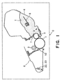
- Figure 1 is a sectional view of the process cartridge in the first embodiment of the present invention.
- Figure 2 is a sectional view of the image forming apparatus in the first embodiment of the present invention, which employs a process cartridge.
- Figure 3 is a graph which shows the relationship between the total amount of the charge current and the shaved amount of the photosensitive member, in the first embodiment'of the present invention.
- Figure 4 is a graph which shows the relationship between the number of the prints produced and the total amount of the charge current, in the first embodiment of the present invention.
- Figure 5 is a block diagram which shows the relationship between the information control section on the main assembly side, and the memory, of the image forming apparatus in the first embodiment of the present invention.
- Figure 6 is a block diagram which shows the relationship between the control section on the main assembly side, and the information within the memory, in the image forming apparatus in the first embodiment of the present invention.
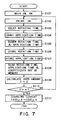
- Figure 7 is a flow chart of the image forming operation in the first embodiment of the present invention.
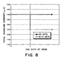
- Figure 8 is a graph which shows the relationship between the drum usage amount data and total amount of the charge current, in the first embodiment of the present invention.
- Figure 9 is a block diagram which shows the relationship between the control portion on the main assembly side, and the information in the memory, when there are a plurality of threshold values pertaining to the drum usage amount computing equation, in the first embodiment of the present invention.
- Figure 10 is a flow chart for the image forming operation when there are a plurality of threshold values pertaining to the drum usage amount computing equation, in the first embodiment of the -present invention.
- Figure 11 is a flow chart for the image forming apparatus when there are a plurality of threshold values pertaining to the drum usage amount computing equation, in the first embodiment of the present invention.
- Figure 12 is a graph which shows the drum usage amount data and line width, in the second embodiment of the present invention.
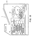
- Figure 13 is a block diagram which shows the relationship between the control section on the main assembly side, and the information in the memory, in the second embodiment of the present invention.
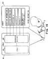
- Figure 14 is a block diagram which shows the control section on the main assembly side and the information in the memory.
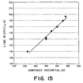
- Figure 15 is a graph which shows the relationship between the development contrast and line width, in the second embodiment of the present invention.
- Figure 16 is a flow chart for the image forming operation in the second embodiment of the present invention.
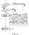
- Figure 17 is a flow chart for the image forming operation in the second embodiment of the present invention.
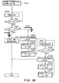
- Figure 18 is a flow chart for the image forming operation in the second embodiment of the present invention.
- Figure 19 is a block diagram which shows the relationship between the control section on the main assembly side and the information within the memory, in the third embodiment of the present invention.
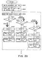
- Figure 20 is a flow chart for the image forming operation in the third embodiment of the present invention.
- Figure 21 is a flow chart for the image forming operation in the third embodiment of the present invention.
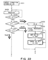
- Figure 22 is a flow chart for the image forming operation in the third embodiment of the present invention.
- Figure 23 is a flow chart for the image forming operation in the third embodiment of the present invention.
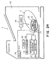
- Figure 24 is a block diagram which shows the control section on the main assembly side, and the information in the memory, in the fourth embodiment of the present invention.
- Figure 25 is a block diagram which shows the relationship between the control portion on the main assembly side and the information in the memory in the fourth embodiment of the present invention.
- Figure 26 is a flow chart for the image forming operation in the fourth embodiment of the present invention.
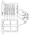
- Figure 27 is a block diagram which shows the relationship between the control portion on the main assembly side and the information in the memory, when there are a plurality of threshold values pertaining to the drum usage computing equation, in the fourth embodiment of the present invention.
- Figure 28 is a flow chart for the image forming operation when there are plurality of threshold values pertaining to the drum usage amount computing equation, in the fourth embodiment of the present invention.
- Figure 29 is a flow chart for the image forming operation which there are plurality of threshold values pertaining to the drum usage amount computing operation, in the fourth embodiment of the present invention.
- Figure 30 is a block diagram which shows the relationship between the control portion on the main assembly side and the information in the memory, in the fifth embodiment of the present invention.
- Figure 31 is a block diagram which shows the relationship between the control portion on the main assembly side and the information in the memory.
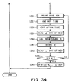
- Figure 32 is a flow chart for the image forming operation in the fifth embodiment of the present invention, in which drum sensitivity is also taken into consideration.
- Figure 33 is a flow chart for the image forming operation in the fifth embodiment of the present invention, in which drum sensitivity is also taken into consideration.
- Figure 34 is a flow chart for the image forming operation in the fifth embodiment of the present invention, in which drum sensitivity is also taken into consideration.
- the image forming apparatus is a laser beam printer which receives image information from a host computer, and outputs the image information as an image. It is an image forming apparatus in which a process cartridge, in which expendables such as an electrophotographic photosensitive member in the form of a drum, that is, a photosensitive drum, developer, and the like, are disposed, can be removably installable.
- a process cartridge in which expendables such as an electrophotographic photosensitive member in the form of a drum, that is, a photosensitive drum, developer, and the like, are disposed, can be removably installable.
- the process cartridge C integrally comprises a developer container 4 and a waste toner container 6.
- the developer container 4 integrally holds: a photosensitive member in the form of a drum, that is, the photosensitive drum 1; a contact charge roller 2 for uniformly charging the photosensitive drum 1; a development sleeve 5 which constitutes a developing means, and is placed virtually in contact with the photosensitive drum 1, its generatrix being parallel to that of the photosensitive drum 1.
- the developer container 4 contains a developer T and rotationally supports the development sleeve 5.
- the waste toner container 6 holds: a cleaning blade which constitutes a cleaning means, and the residual toner particles removed from the photosensitive drum 1 by the cleaning blade 10.
- This process cartridge C is removably installed into an installing means 101 ( Figure 2) provided in the main assembly 100 of the image forming apparatus, by a user.
- the development sleeve 5 of the developing means comprises a nonmagnetic aluminum base with a diameter of 16 mm, and a resin layer coated on the peripheral surface of the base.
- the resin layer contains electrically conductive particles.
- a magnetic roll with four magnetic poles is placed in the development sleeve 5.
- a development blade that is, a developer regulating member 7, is attached to the shell of the developer container 4.
- the developer regulating member 7 in this embodiment is formed of silicone rubber with a hardness of approximately 40 deg.
- contact pressure a predetermined amount of pressure in a range of 30 - 40 gf/cm (contact load per centimeter in the longitudinal direction of the development sleeve 5).
- the developer T stored in the developer container 4 in this embodiment is a nonmagnetic single component toner (hereinafter, toner) and is negatively chargeable.
- the ingredients of the developer T are copolymer of styrene-butyl-acrylate (100 parts in weight) as bonding resin, magnetic particles (80 parts in weight), monoazoic complex (2 parts in weight) as negative charge controlling agent, and polypropylene with low molecular weight (3 parts in weight) as wax. In production, these ingredients are mixed and melted in a double axis extruder heated to 140 °C. After cooling, the mixture is pulverized into relatively large particles by a hammer mill, and then, further pulverized into microscopic particles by a jet mill.
- the thus obtained microscopic particles are classified by air flow, collecting particles with a weight average diameter of 5.0 ⁇ m. Then, one part in weight of microscopic hydrophobic silica particles is mixed by one part in weight into 100 parts in weight of the classified particles with a weight average diameter of 5.0 ⁇ m with the use of Henschel mixer to yield the developer T in this embodiment.
- the toner particles with a weight average particle diameter within a range of 3.5 - 7.0 ⁇ m (mostly, 6 ⁇ m) are used as the developer in this embodiment.
- the development bias applied to the development sleeve 5 is combination of a DC voltage of -450 V, and an AC voltage with a rectangular waveform, a peak-to-peak voltage of 1600 V, and a frequency of 2300 Hz, when the gap between the photosensitive drum 1 and development sleeve 5 is approximately 300 pm, for example.
- toner stirring means 8 in the developer container, that is, the toner container 4, which rotates once every six seconds to convey the toner T in the toner container 4 to the development region, while loosening the toner T.
- the development roller 2 comprises a metallic core, and an electrically conductive elastic layer formed on the peripheral surface of the metallic core. It is rotationally supported at the longitudinal ends of the metallic core, being kept in contact with the peripheral surface of the photosensitive drum 1 with the application of a predetermined amount of pressure. It follows the rotation of the photosensitive drum 1.
- a compound voltage (Vac + Vdc) comprising an AC component Vac with a peak-to-peak voltage Vpp of twice the charge start voltage, and a DC component Vdc, is applied from the high voltage power source provided within the image forming apparatus main assembly 100 through the metallic core.
- the peripheral surface of the photosensitive drum 1 is uniformly charged by the charge roller 2 which is in contact with the peripheral surface of the photosensitive drum 1.
- the charge bias applied to the charge roller 2 is combination of a DC voltage of -600 V, and an AC voltage with a sinusoidal waveform, a Vpp of 2 kV, and a frequency of 1500 Hz. Its effective current value is 1400 ⁇ A.
- the photosensitive drum 1 is charged to the potential level Vd of -600 V.
- the potential level VL of an exposed area is -150 V.
- the exposed areas are reversely developed.
- FIG. 2 shows the general structure of a laser printer L, that is, an image forming apparatus.
- the cylindrical photosensitive drum 1 as a latent image bearing member is rotated in the direction of an arrow mark about its rotational axis supported by the image forming apparatus main assembly 100.
- a latent image is formed on the peripheral surface of the photosensitive drum 1 by an exposing apparatus 3.
- the latent image formed on the peripheral surface of the photosensitive drum 1 is supplied with the toner T by the development sleeve 5, which is a part of the developing apparatus, becoming a visible image.
- a bias supplying power source (unillustrated) is connected, which applies the combination of DC bias and AC bias so that a proper amount of development bias is provided.
- the toner image formed'on the photosensitive drum 1 by visualizing the latent image on the photosensitive drum 1 with the toner T as described above is transferred onto a recording medium 20 such as a piece of recording paper by a transfer roller 9.
- the recording medium 20 is fed by a sheet feeding roller 21, and is sent to the transfer roller 9, in synchronism with the toner image on the photosensitive drum 1, by a registration roller (unillustrated).
- the visual image formed by the toner T is conveyed, along with the transfer medium 20, to a fixing apparatus 2, in which it is fixed to the recording medium 20 with the application of heat and pressure, becoming a permanent image.
- the particles of the toner T on the photosensitive drum 1, which were not transferred onto the recording medium 20, that is, the residual toner particles on the photosensitive drum 1, are removed by the cleaning blade 10, and are collected in the waste toner container 6. Thereafter, the peripheral surface of the photosensitive drum 1 is again charged by the charging apparatus 2 to be subjected to the above described processes.
- the cartridge C is provided with a memory 22, and a communicating section 23 for controlling the processes of reading from, and writing into, the memory 22.
- the communicating section 23 is located on the downwardly facing surface of the bottom wall of the waste toner container 6.
- the communicating section 23 on the cartridge side and a control section 24 on the image forming apparatus main assembly side are positioned in such a manner that as the cartridge C is installed into the image forming apparatus main assembly 100, they face each other.
- the control section 24 on the main assembly side is given a function to double as the transmitting section.
- the memory 22 to be used with the present invention there is no restriction; it may be any ordinary semiconductor electronic memory.
- a noncontact memory enabled to be read or written by an IC through electromagnetic wave transmission is preferable, because the employment of such a memory makes unnecessary the physical contact between the communicating section on the cartridge side and the control section on the apparatus main assembly side, eliminating therefore the possibility of contact failure which might result from the way the cartridge C is installed. As a result, it becomes possible to carry out highly reliable control.
- control section 24 and communicating section 23 constitutes the control- communicating means for reading information from, or writing information into, the memory 22.
- the capacity of the memory 22 should be large enough to store a plurality of data, for example, cartridge identification data, which will be described later, or the values which represent the characteristics of each cartridge.
- the amount of the usage of the cartridge C is continuously recorded.
- the type of the value which represents the amount of the cartridge usage stored in the memory 22 as long as it can be usable for the image forming apparatus to determine the amount of cartridge usage.
- it may be the length of the rotation time of each element in the cartridge, the length of the bias application time, the amount of the remaining toner, the print count, the number of image dots formed on the photosensitive drum 1, the cumulative length of time the laser beam is emitted to expose the photosensitive drum 1, the thickness of the photosensitive layer of the photosensitive drum 1, and a weighted combination of the preceding factors.
- cartridge specifications which represent specific properties of each cartridge may be used as parameters for adjusting processing conditions, and they may be those attached to each cartridge when it is shipped from a factory.
- they may be lot numbers of the photosensitive drum 1, toner T, development sleeve 5, and charge roller 2, the specific value representing the sensitivity of the photosensitive drum 1, the threshold value, and the coefficient pertaining to the equation weighted by the lengths of charge bias application time and photosensitive drum driving time.
- the processing conditions are controlled based on the relationship between the two sets of information stored in the memory 22. More specifically, the data within the memory 22 are computed by the control section 24 on the apparatus main assembly side, and the resultant electrical signals are sent to appropriate processing units to change the high voltage output, processing speed, amount of laser light, and the like.
- an AC application system is employed along with the charge roller 2 as a charging means.
- negative and positive voltages are alternately applied, triggering electrical discharge in alternating directions.
- This electrical discharge seriously deteriorates the peripheral surface of the photosensitive drum 1 as an object to be charged, and the deteriorated portions of the peripheral surface of the photosensitive drum 1 are shaved away due to the friction between the peripheral surface of the photosensitive drum I and the member such as the cleaning blade 10 which comes into contact with the peripheral surface of the photosensitive drum 1.
- the photosensitive layer of the photosensitive drum 1 becomes gradually thinner with the apparatus usage.
- the photosensitive layer of the photosensitive drum 1 becomes less than a certain value, the photosensitive layer becomes inferior in its function.
- the peripheral surface of the photosensitive drum 1 fails to be uniformly charged, displaying microscopic irregularities in terms of potential level, or reduces in the capacity to hold electrical charge, sometimes failing to be charged. Therefore, the length of the service lives of the image forming apparatus or a process cartridge corresponds to the print count which accumulates before the thickness of the photosensitive layer reduces to its limit.
- a sandy patch means an image area covered with black dots, in an image outputted through a reversal development process, the positions of which correspond to the areas of the peripheral surface of the photosensitive drum 1 insufficiently charged because the amount of the electrical discharge caused by the charge roller 2 was too small. It has been known that the sandy patches are more apparent which the peak-to-peak voltage of the oscillating voltage applied to the charge roller 2 is small.
- the photosensitive layer of the photosensitive drum 1 is thick enough to maintain the sharpness of a latent image, and the amount of electrical discharge is exact; in other words, it is not small enough to cause the sandy patch traceable to the insufficiency in the amount of electrical discharge to appear, and yet not large enough to accelerate the deterioration of the photosensitive layer.
- Figure 3 shows the relationship between the shaved amount ⁇ d ( ⁇ m/print count) of the photosensitive member and the total amount of the charge current I total per unit of time. It is evident from Figure 3 that the smaller the total amount of the charge current, the smaller the shaved amount of the photosensitive material.
- a thickness d of the photosensitive layer represents the actual thickness of the photosensitive layer measured using a film thickness gauge (Permascope E-1: product of Fischer).
- Figure 4 shows the relationship between the print count and the total amount of the charge current I total correspondent to nonappearance of the sandy patches. It is evident from Figure 4 that there are changes in the total amount of the charge current in regions A and B. It may be thought that these changes, that is, the appearance of the sandy patches, are traceable to the charge roller 2, and the thickness of the surface layer of the photosensitive drum 1.
- the dominant cause of the charges in the region A is charge roller 2. More specifically, as the print count increases, the charge roller 2 is contaminated with the external additive of the toner, reversely charged toner, and paper dust, being changed in charging performance; in other words, the total amount of the charge current per unit of time reduces.
- the dominant cause of the changes is the photosensitive member. More specifically, each time a printing cycle is repeated, the peripheral surface of the photosensitive member is shaved by a small amount; the photosensitive layer, that is, the surface layer of the photosensitive member, becomes thinner. As the photosensitive layer becomes thinner, the impedance of the photosensitive member reduces, increasing the voltage applied to the photosensitive drum when charging the photosensitive drum. As a result, it becomes easier for electric discharge to occur. Consequently, the total amount of the charge current per unit of time decreases.
- the charge current value must be set in consideration of both the condition of the charge roller 2, and the thickness of the photosensitive layer of the photosensitive drum 1.
- condition of the charge roller 2 and the thickness of the photosensitive layer of the photosensitive drum 1 are dependent upon the characteristics of the various components in a cartridge, and the amount of their usage.
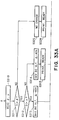
- the cartridge C side is provided with the memory 22 and communicating section 23, whereas the apparatus main assembly side is provided with control section 24 which comprises a control portion 25, a computing portion 26, a photosensitive member rotation control portion 27, a charge bias application time detecting portion 28, and the like.
- Figure 6 shows the information stored in the memory 22. Although there are various kinds of information storable in the memory 22, it is assumed that, in this embodiment, at least, the following information is stored: information A or the length of time the charge bias was applied; information B or the length of time the photosensitive member was rotated; coefficient ⁇ pertaining to the drum usage amount computing equation; and ⁇ (information regarding timing) or the threshold value pertaining to the drum usage amount computing equation.
- the threshold value and coefficient change depending on the sensitivity, material, and thickness at the time of production, of the photosensitive drum 1, and the characteristics of the charge roller 2, and therefore, values in accordance with these factors and characteristics are written into the memory 22 at the time of cartridge manufacture.
- the information in the memory 22 is rendered always transmittable between the memory 22 and the computing portion 26 of the control section 24 on the main assembly side.
- the computation is carried out based on the above listed information, and the results of the computation are compared to the stored data by the control portion 25.
- the results are stored in the memory 22 of the process cartridge C.
- the data regarding the length of the photosensitive member rotation time, and the data regarding the length of the charge bias application time are continuously stored in the memory 22, and the drum usage data are computed whenever the driving of the photosensitive drum 1 is stopped.
- the length of the service life of the photosensitive drum 1, which used to be 13000 in terms of print count, could be extended to 17000.
- drum usage data threshold values may be used, although only one is used in this embodiment. The threshold value varies depending on various factors, for example, difference in manufacture lot, and therefore, the threshold value stored in each cartridge in this embodiment is selected to reflect these factors, so that image quality can be maintained regardless of differences among cartridges and length of their usage.
- Figure 6 shows the information within the memory 22 when a plurality of drum usage data threshold values are used. At least the following kinds of information are stored in the memory 22: information A or the length of time the charge bias was applied; information B or the length of time the photosensitive member was rotated; coefficient ⁇ pertaining to the drum usage amount data computing equation; and ⁇ 1, ⁇ 2, ... ⁇ n or the threshold values pertaining to the drum usage amount data computing equation, although there are various other kinds of information stored therein.
- the information in the memory 22 is rendered constantly transmittable between the memory 22 and the computing portion 26 within the control section 24 on the main assembly side. The results of the computation carried out based on these data are compared to the referential data by the control portion 25.
- Figures 10 and 11 show the flow chart for switching the current value twice or more.
- the amount of the charge current was varied based on the cumulative length of the usage time of the photosensitive drum 1 as the process cartridge C usage data to be stored in the memory 22 in the process cartridge C, and two characteristic values, that is, the threshold value pertaining to the amount of the usage of the photosensitive drum 1, and the coefficient.
- This embodiment is distinctive in that another characteristic value which represents the information regarding the sensitivity of the photosensitive drum 1 is employed in addition to the data relied upon in the first embodiment, and the DC voltage applied to charge the photosensitive drum 1, and the DC voltage applied for development, are varied based on these data.
- the cartridge C is provided with a memory 62 and a communicating portion 63
- the apparatus main assembly side 100 is provided with control section 64 which comprises a drum sensitivity detecting means 60, a control portion 65, a computing portion 66, a photosensitive member rotation control portion 67, a charge bias application time detecting portion 68, a sensitivity conversion table 70, and the like.
- Figure 14 shows the information stored in the memory 62.
- information A or the length of time the charge bias was applied information B or the length of time the photosensitive member was rotated; coefficient ⁇ for the drum usage amount computing equation; ⁇ , ⁇ or the threshold values for the equation for computing the length of drum usage; and L.M.H or drum sensitivity threshold values.
- the threshold value and coefficient change depending on the sensitivity, material, and thickness at the time of operation, of the photosensitive drum 1, and the characteristics of the charge roller 2, and therefore, values in accordance with these factors and characteristics are written into the memory 62 at the time of cartridge manufacture.
- the drum usage data D is computed by the computing portion 66 using the information B or the cumulative length of time the photosensitive member was rotated data, which is obtained from the photosensitive member rotation control portion 67, the information A or the cumulative length of time the charge bias was applied, which is obtained from the charge bias application time detecting portion 68, and a conversion equation weighted by a predetermined weighting coefficient ⁇ : D - A + (B x ⁇ ).
- the results are stored in the memory 62 of the process cartridge C.
- the data regarding the length of the photosensitive member rotation time, and the data regarding the length of the charge bias application time are continuously stored in the memory 62, and the drum usage data are computed whenever the driving of the photosensitive drum 1 is stopped.
- two threshold values ⁇ and ⁇ are used, and their relationship is: ⁇ ⁇ ⁇ .
- Figure 15 shows the relationship between the contrast potential level and line width.
- the contrast potential level means the absolute value of the difference between the potential level of the DC component of development bias, and the potential level VL of the drum.
- the drum sensitivity detecting portion 60 within the control section of the main assembly reads out the sensitivity value in the memory 62.
- the drum sensitivity is divided into three ranges, L, M and H, depending on the potential level VL of each photosensitive drum at the time of shipment.
- the charge and development DC voltages are varied according to each of the three drum sensitivity ranges, with reference to the sensitivity conversion table 70 in the control portion 65.
- the values of L and M are rendered lower or higher than the value of M by a unit of ⁇ 20 V, respectively.
- the values of L and H are rendered lower or higher than the value of the M by a unit of ⁇ 10 V, respectively.
- the data regarding the length of the photosensitive member rotation time, and the data regarding the length of the charge bias application time, are to be continuously stored in the memory, and the drum usage data are to be computed whenever the driving of the photosensitive drum 1 is stopped.
- the charge and development DC biases applied in the initial period of an image forming operation are adjusted for each cartridge, according to the drum sensitivity information and drum usage data, prior to the step of image formation standby. Thereafter, the biases are varied to proper levels in accordance with the characteristic value of each cartridge, during the operation, so that the line width remains stable.
- the biases are lowered by a single unit of change during each control subsequence. However, it may be lowered by a plurality of units per control sub-sequence.
- charge and development voltages are varied in potential level to control the image formation process. However, they may be varied in frequency. Further, the amount of exposure may be varied. Further, in this embodiment, the value computed with the use of the above described equation is used as the usage data. However, the value of print count or cumulative length of photosensitive member rotation time alone may be used as the usage data.
- drum usage amount threshold value record is used in addition to the above described information, which characterizes this embodiment. With the addition of the drum usage amount threshold value record, computation becomes unnecessary even prior to the step of "image formation standby ON", reducing the time before the first print can be produced.
- threshold value for the usage is the same as those in the second embodiment, and therefore, their descriptions will be omitted here.
- Figure 19 shows the information within the memory 62.
- information A or the length of time the charge bias was applied information B or the length of time the photosensitive member was rotated
- coefficient ⁇ for the equation for computing the length of drum usage ⁇ , ⁇ or the threshold values for the equation for computing the length of drum usage
- L.M.H or drum sensitivity threshold values drum usage amount record ⁇
- drum usage amount record ⁇ drum usage amount record ⁇ .
- the computation is unnecessary even prior to the step of "image formation standby ON", reducing the time before the first print can be produced while providing the same effects as those in the second embodiment.
- two threshold values are provided pertaining to the drum usage data as in the second embodiment.
- three or more threshold values may be provided on the basis of the characteristics of a cartridge, for example, the initial condition of each cartridge, and cartridge structure.
- bias was lowered by a single unit of variation per sub-sequence. However, it may be raised or lowered by a plurality of units of variation.
- charge and development voltages were varied in potential level to adjust the processing condition. However, according to circumstances, charge and development voltages may be varied in frequency, or the amount of exposure may be varied.
- the number of the threshold values stored in the memory 22 of the cartridge C may be plural, and the value of the charge current may be switched twice or more. With the above described control, it is possible to satisfactorily charge the photosensitive drum 1 while keeping the charge current value as small as possible, and therefore, the service life of the photosensitive drum 1 is extended.
- control section 24 on the main assembly side has a data storage memory 13, a control portion 25, a computing portion 26, a photosensitive member rotation control portion 27, a charge bias application time detecting portion 28, a communicating portion 14, and the like.
- the cartridge C has a memory 22 and a communicating portion 23.
- a coefficient ⁇ pertaining to the drum usage computation equation, a threshold value ⁇ pertaining to drum usage amount, and information X pertaining to cartridge characteristics are stored in the memory 22 of the cartridge C.
- the ID information means information for the image forming apparatus main assembly 100 to detect whether or not the cartridge C has been replaced. In other words, if may be any type of information as long as it provides identity of each cartridge. More specifically, it is a serial number of the cartridge C or the like.
- the threshold value ⁇ and coefficient ⁇ are stored in the memory 22 at the time of shipment. These values vary depending upon the sensitivity and material of the photosensitive drum, and the surface condition of the charge roller 2, and the like.
- the driving of the cartridge C is started by the photosensitive member rotation control portion 27, to start an image formation process.
- the drum usage amount is computed.
- the results are cumulative stored in the memory 13 within the apparatus main assembly 100.
- the value of the cumulative stored drum usage amount is compared with the threshold value ⁇ in the memory 22 of the cartridge C.
- a control signal is sent to the charge bias power source 29 from the control portion 25 to change the charge bias.
- the drum usage amount D continues to be cumulative stored.
- the drum usage amount D is reset.
- the data regarding the length of the photosensitive member rotation time, and the data regarding the length of the charge bias application time, are to be continuously stored in the memory, and the drum usage data are to be computed whenever the driving of the photosensitive drum 1 is stopped.
- the length of the service life of the photosensitive drum 1, which used to be 13000 in terms of print count, could be extended to 17000.
- current switching is done only once in this embodiment, it may done in a plurality of steps depending upon the characteristics of individual cartridges. Further, the current value may be raised or lowered depending upon the condition of each cartridge. Also, two or more threshold values may be used pertaining to the drum usage data, although only one is used in this embodiment.
- Figure 27 shows the information stored within the memory 22 when a plurality of threshold values pertaining to the drum usage data are used.
- the cartridge ID information X the coefficient ⁇ for the drum usage amount computing equation
- three threshold values ⁇ 1, ⁇ 2, ⁇ 3 pertaining to the drum usage amount, although there are various other kinds of information stored therein.
- These types of information are rendered continually transmittable between the memory 22 of the cartridge C and the computing portion 26 within the control section 24 on the main assembly side. The results of the computation carried out based on these types information are compared to the referential data by the control portion 25.
- Figures 28 and 29 show the flow chart for switching the current value twice or more.
- the amount of the charge current was varied based on the drum usage amount, as the usage data, in the memory 22, and two characteristic values, that is, the coefficient pertaining to the drum usage amount computing equation and the threshold value pertaining to the usage data.
- This embodiment is distinctive in that additional information, which pertains to the characteristics of the photosensitive drum 1, that is, the sensitivity of the photosensitive drum 1, is employed in addition to the data relied upon in the fourth embodiment, and the DC voltage applied to charge the photosensitive drum 1, and the DC voltage applied for development, are varied based on these data.
- control section 64 on the main assembly side has data storage memory 13, a control portion 65, a computing portion 66, a photosensitive member rotation control portion 67, a charge bias application time detecting portion 68, a communication portion 14, whereas the cartridge C side has a memory 62 and a communicating portion 63.
- Figure 31 shows the information stored in the memory 62.
- coefficient ⁇ pertaining to the equation for computing the length of drum usage
- threshold values ⁇ and ⁇ pertaining to the equation for computing the drum usage
- drum sensitivity threshold values L.M.H and also a cartridge identification information X as in the fourth embodiment.
- the threshold values ⁇ and ⁇ , coefficient ⁇ , and drum sensitivity are stored in the memory 62 at the time of shipment. These values are selected to be optimal for the characteristics of the photosensitive drum, and other components used in a given cartridge.
- control portion 65 accesses the memory 62, an reads the drum sensitivity value.
- control portion 65 sets the initial level of the bias applied by the development DC bias power source 71. In this embodiment, it is set at -510 V, -490 V and -470 V, when the drum sensitivity is in the ranges of L, M and H, correspondingly.
- the drum usage amount is computed as follows, as in the first embodiment.
- B stands for the cumulative data of the photosensitive member rotation time, which is obtained from the photosensitive member rotation control portion 67
- A stands for the cumulative length of time the charge bias was applied, which is obtained from the charge bias application time detecting portion 68
- ⁇ stands for a weighting coefficient read out of the memory 22.
- the results are cumulatively stored in the memory 13 within the apparatus main assembly 100.
- the value of the cumulatively stored drum usage amount is compared with the threshold values ⁇ and ⁇ in the memory 62 of the cartridge C.
- the threshold value ⁇ is rendered smaller than the threshold value ⁇ ( ⁇ ⁇ ⁇ ).
- the value of the drum usage amount D is greater than the value of ⁇ , the value of the development DC bias applied from the development DC bias power source 71 is lowered to 20 V through the control portion 65. More specifically, when the drum sensitivity is in the range L, M and H, the development bias is switched to -490 V, -470 V and -450 V, correspondingly.
- the amount D of the usage of the photosensitive drum 1 increases. Then, as the drum usage amount D becomes greater than threshold value ⁇ , the value of the development bias applied from the development DC bias power source 71 is lowered by 20 V through the control portion 65. More specifically, when the drum sensitivity is in the range L, M and H, the development bias is switched to -470 V, -450 V and -430 V, correspondingly.
- the data regarding the length of the photosensitive member rotation time, and the data regarding the length of the charge bias application time, are continuously stored in the memory, and the drum usage data are computed whenever the driving of the photosensitive drum 1 is stopped.
- the charge and development DC biases applied in the initial period of an image forming operation are adjusted for each cartridge, according to the drum sensitivity information and drum usage data, prior to the step of "image formation standby ON". Thereafter, the biases are varied to proper levels in accordance with the characteristic value of each cartridge, during the operation, so that the line width remains stable.
- the biases were lowered by a single unit of change during each control subsequence. However, it may be lowered by a plurality of units per control subsequence.
- development voltage is varied in potential level to control the image forming process.
- charge DC voltage may be varied as the same time as the development voltage in order to maintain the contrast between the potential levels of the charge voltage and development voltage.
- the other factors that is, the frequencies of the charge and development voltages, and the amount of exposure, may be altered to control the image forming process, which is obvious.
Landscapes
- Engineering & Computer Science (AREA)
- Computer Vision & Pattern Recognition (AREA)
- Physics & Mathematics (AREA)
- General Physics & Mathematics (AREA)
- Electrophotography Configuration And Component (AREA)
- Control Or Security For Electrophotography (AREA)
Applications Claiming Priority (4)
| Application Number | Priority Date | Filing Date | Title |
|---|---|---|---|
| JP29458899 | 1999-10-15 | ||
| JP29458499A JP2001117425A (ja) | 1999-10-15 | 1999-10-15 | プロセスカートリッジ用メモリー媒体、プロセスカートリッジ、電子写真画像形成装置及び電子写真画像形成システム |
| JP29458899A JP2001117468A (ja) | 1999-10-15 | 1999-10-15 | プロセスカートリッジ用メモリー媒体、プロセスカートリッジ、電子写真画像形成装置及び電子写真画像形成システム |
| JP29458499 | 1999-10-15 |
Publications (3)
| Publication Number | Publication Date |
|---|---|
| EP1093034A2 true EP1093034A2 (de) | 2001-04-18 |
| EP1093034A3 EP1093034A3 (de) | 2002-06-19 |
| EP1093034B1 EP1093034B1 (de) | 2008-08-27 |
Family
ID=26559903
Family Applications (1)
| Application Number | Title | Priority Date | Filing Date |
|---|---|---|---|
| EP00309031A Expired - Lifetime EP1093034B1 (de) | 1999-10-15 | 2000-10-13 | Bilderzeugungsgerät und von diesem Gerät abnehmbare Einheit |
Country Status (3)
| Country | Link |
|---|---|
| US (3) | US6597876B1 (de) |
| EP (1) | EP1093034B1 (de) |
| DE (1) | DE60040044D1 (de) |
Cited By (4)
| Publication number | Priority date | Publication date | Assignee | Title |
|---|---|---|---|---|
| EP1229398A3 (de) * | 2001-01-12 | 2002-10-16 | Seiko Epson Corporation | Verfahren und Vorrichtung zur Steuerung der Bilddichte eines Tonerbildes |
| EP1353240A2 (de) | 2002-04-09 | 2003-10-15 | Canon Kabushiki Kaisha | Arbeitseinheit, Speichermedium für die Arbeitseinheit, Bilderzeugungsgerät und Bilderzeugungssteuerungssystem |
| EP1434112A2 (de) | 2002-11-08 | 2004-06-30 | Canon Kabushiki Kaisha | Bilderzeugungsgerät, Prozesskartusche, Bilderzeugungssystem, und hierfür Speichermedium |
| CN100367131C (zh) * | 2002-11-08 | 2008-02-06 | 佳能株式会社 | 成像设备、盒部件、成像系统及用于盒部件的存储介质 |
Families Citing this family (10)
| Publication number | Priority date | Publication date | Assignee | Title |
|---|---|---|---|---|
| JP2001100617A (ja) * | 1999-09-29 | 2001-04-13 | Canon Inc | プロセスカートリッジ及び電子写真画像形成装置 |
| JP2002062780A (ja) * | 2000-08-16 | 2002-02-28 | Canon Inc | 画像形成装置および方法 |
| US6607438B2 (en) | 2001-09-28 | 2003-08-19 | Igy | Gaming device having termination variables |
| JP4387713B2 (ja) * | 2002-07-25 | 2009-12-24 | キヤノン株式会社 | 画像形成装置 |
| JP3754980B2 (ja) * | 2004-02-10 | 2006-03-15 | キヤノン株式会社 | 画像形成装置群 |
| US9296214B2 (en) | 2004-07-02 | 2016-03-29 | Zih Corp. | Thermal print head usage monitor and method for using the monitor |
| US8721203B2 (en) | 2005-10-06 | 2014-05-13 | Zih Corp. | Memory system and method for consumables of a printer |
| JP4332808B2 (ja) * | 2006-08-07 | 2009-09-16 | 村田機械株式会社 | 画像形成装置 |
| JP4967667B2 (ja) * | 2007-01-11 | 2012-07-04 | コニカミノルタビジネステクノロジーズ株式会社 | 画像形成装置 |
| US10915064B2 (en) | 2019-03-28 | 2021-02-09 | Brother Kogyo Kabushiki Kaisha | Image forming apparatus including drum cartridge having photosensitive drum and toner cartridge having developing roller |
Family Cites Families (26)
| Publication number | Priority date | Publication date | Assignee | Title |
|---|---|---|---|---|
| JPS6275667A (ja) * | 1985-09-30 | 1987-04-07 | Konishiroku Photo Ind Co Ltd | 画像形成装置 |
| US4961088A (en) * | 1989-04-20 | 1990-10-02 | Xerox Corporation | Monitor/warranty system for electrostatographic reproducing machines using replaceable cartridges |
| JPH04299375A (ja) | 1991-03-28 | 1992-10-22 | Tokyo Electric Co Ltd | 電子写真装置 |
| GB9119483D0 (en) * | 1991-09-11 | 1991-10-23 | Xerox Corp | Replaceable sub-assemblies for electrostatographic reproducing machines |
| US5272503A (en) | 1992-09-02 | 1993-12-21 | Xerox Corporation | Replaceable sub-assemblies for electrostatographic reproducing machines |
| JPH07281564A (ja) * | 1994-04-12 | 1995-10-27 | Fuji Xerox Co Ltd | カートリッジ寿命の検知方法 |
| US5923917A (en) * | 1995-10-25 | 1999-07-13 | Canon Kabushiki Kaisha | Image forming apparatus, and a cartridge having a developer container detachably mountable on such apparatus |
| JP3559630B2 (ja) | 1995-10-25 | 2004-09-02 | キヤノン株式会社 | 画像形成装置 |
| JP3285785B2 (ja) | 1996-12-20 | 2002-05-27 | キヤノン株式会社 | 像担持体寿命検知方法、画像形成装置、及びプロセスカートリッジ |
| JP3566468B2 (ja) | 1996-07-23 | 2004-09-15 | キヤノン株式会社 | 感光体の寿命検知方法、画像形成装置、及びプロセスカートリッジ |
| DE69627803T2 (de) | 1995-12-26 | 2004-04-01 | Canon K.K. | Lebensdaueranzeigegerät eines aufgeladenen Bildträgerteiles, Anzeigeverfahren dafür, und Bilderzeugungsgerät |
| JPH09179460A (ja) | 1995-12-26 | 1997-07-11 | Canon Inc | 被帯電体寿命検知装置、これを備えたプロセスユニットおよび画像形成装置 |
| JPH09190143A (ja) | 1996-01-09 | 1997-07-22 | Canon Inc | プロセスカートリッジ及び電子写真画像形成装置 |
| JP3311248B2 (ja) * | 1996-07-26 | 2002-08-05 | キヤノン株式会社 | プロセスカートリッジおよび画像形成装置 |
| DE69730920T2 (de) | 1996-07-26 | 2005-08-25 | Canon K.K. | Bilderzeugungsgerät und dazu montierbare Prozesskassette |
| JPH1039693A (ja) | 1996-07-26 | 1998-02-13 | Canon Inc | 画像形成装置及びプロセスカートリッジ |
| JP3308824B2 (ja) | 1996-07-26 | 2002-07-29 | キヤノン株式会社 | プロセスカートリッジおよび画像形成装置 |
| JPH1039723A (ja) | 1996-07-26 | 1998-02-13 | Canon Inc | プロセスカートリッジおよび画像形成装置 |
| JP3311250B2 (ja) * | 1996-07-31 | 2002-08-05 | キヤノン株式会社 | プロセスカートリッジ及び画像形成装置 |
| JP3432090B2 (ja) | 1996-10-31 | 2003-07-28 | キヤノン株式会社 | プロセスカートリッジ及び電子写真画像形成装置 |
| US6940613B1 (en) | 1997-04-11 | 2005-09-06 | Xerox Corporation | System for managing replaceable modules in a digital printing apparatus |
| JP3452776B2 (ja) * | 1997-10-28 | 2003-09-29 | シャープ株式会社 | 画像形成装置 |
| US6137966A (en) * | 1998-04-16 | 2000-10-24 | Canon Kabushiki Kaisha | Image forming apparatus |
| US5995774A (en) * | 1998-09-11 | 1999-11-30 | Lexmark International, Inc. | Method and apparatus for storing data in a non-volatile memory circuit mounted on a printer's process cartridge |
| JP4566346B2 (ja) | 2000-06-27 | 2010-10-20 | キヤノン株式会社 | 画像形成装置 |
| JP2002049225A (ja) | 2000-07-31 | 2002-02-15 | Canon Inc | 電子写真画像形成装置及びプロセスカートリッジ |
-
2000
- 2000-10-13 DE DE60040044T patent/DE60040044D1/de not_active Expired - Lifetime
- 2000-10-13 US US09/689,734 patent/US6597876B1/en not_active Expired - Lifetime
- 2000-10-13 EP EP00309031A patent/EP1093034B1/de not_active Expired - Lifetime
-
2002
- 2002-10-09 US US10/266,744 patent/US6608975B2/en not_active Expired - Lifetime
- 2002-10-09 US US10/266,687 patent/US6694107B2/en not_active Expired - Lifetime
Cited By (8)
| Publication number | Priority date | Publication date | Assignee | Title |
|---|---|---|---|---|
| EP1229398A3 (de) * | 2001-01-12 | 2002-10-16 | Seiko Epson Corporation | Verfahren und Vorrichtung zur Steuerung der Bilddichte eines Tonerbildes |
| US6650849B2 (en) | 2001-01-12 | 2003-11-18 | Seiko Epson Corporation | Method of and apparatus for controlling image density of toner image based on high and low-density correlation data |
| EP1353240A2 (de) | 2002-04-09 | 2003-10-15 | Canon Kabushiki Kaisha | Arbeitseinheit, Speichermedium für die Arbeitseinheit, Bilderzeugungsgerät und Bilderzeugungssteuerungssystem |
| EP1353240A3 (de) * | 2002-04-09 | 2009-03-04 | Canon Kabushiki Kaisha | Arbeitseinheit, Speichermedium für die Arbeitseinheit, Bilderzeugungsgerät und Bilderzeugungssteuerungssystem |
| EP1434112A2 (de) | 2002-11-08 | 2004-06-30 | Canon Kabushiki Kaisha | Bilderzeugungsgerät, Prozesskartusche, Bilderzeugungssystem, und hierfür Speichermedium |
| CN100349075C (zh) * | 2002-11-08 | 2007-11-14 | 佳能株式会社 | 成像设备、盒部件、成像系统及用于盒部件的存储介质 |
| CN100367131C (zh) * | 2002-11-08 | 2008-02-06 | 佳能株式会社 | 成像设备、盒部件、成像系统及用于盒部件的存储介质 |
| EP1434112A3 (de) * | 2002-11-08 | 2011-04-20 | Canon Kabushiki Kaisha | Bilderzeugungsgerät, Prozesskartusche, Bilderzeugungssystem, und hierfür Speichermedium |
Also Published As
| Publication number | Publication date |
|---|---|
| EP1093034B1 (de) | 2008-08-27 |
| US20030031478A1 (en) | 2003-02-13 |
| US6608975B2 (en) | 2003-08-19 |
| DE60040044D1 (de) | 2008-10-09 |
| US6597876B1 (en) | 2003-07-22 |
| US20030031477A1 (en) | 2003-02-13 |
| US6694107B2 (en) | 2004-02-17 |
| EP1093034A3 (de) | 2002-06-19 |
Similar Documents
| Publication | Publication Date | Title |
|---|---|---|
| KR100532181B1 (ko) | 화상 형성 장치, 카트리지, 화상 형성 시스템 및카트리지용 저장 매체 | |
| EP1055979B1 (de) | Bilderzeugungsgerät und in diesem Gerät montierbare Arbeitseinheit | |
| EP1093034B1 (de) | Bilderzeugungsgerät und von diesem Gerät abnehmbare Einheit | |
| EP0555102B1 (de) | Bilderzeugungsgerät mit einem Auflade-Element in Kontakt mit dem Bildträgerelement | |
| US6850714B2 (en) | Image forming apparatus, cartridge, image forming system and storage medium | |
| KR100639734B1 (ko) | 화상 형성 장치, 카트리지, 화상 형성 시스템 및카트리지용 저장 매체 | |
| KR100718610B1 (ko) | 화상 형성 장치, 카트리지, 및 저장 매체 | |
| US6324357B1 (en) | Image forming apparatus capable of properly controlling ac voltage applied to a charger | |
| US7058319B2 (en) | Image forming apparatus and cartridge detachably mountable thereto | |
| EP0532308A2 (de) | Auswechselbare Einzelteile für elektrostatografische Kopiermaschinen | |
| JP2001117425A (ja) | プロセスカートリッジ用メモリー媒体、プロセスカートリッジ、電子写真画像形成装置及び電子写真画像形成システム | |
| US20020057916A1 (en) | Electrophotographic image forming apparatus and process cartridge | |
| JP2001117468A (ja) | プロセスカートリッジ用メモリー媒体、プロセスカートリッジ、電子写真画像形成装置及び電子写真画像形成システム | |
| EP0987608B1 (de) | Aus einem Bilerzeugungsgerät-Hauptkörper abnehmbare Einheit und Bilderzeugungsverfahren und Gerät | |
| KR20020014733A (ko) | 접촉식 대전장치 및 이를 이용한 전자 사진식 인쇄장치 | |
| KR100485860B1 (ko) | 화상형성 장치의 현상전압 제어장치 및 방법 | |
| KR100553894B1 (ko) | 토너 카트리지 | |
| JP2002244364A (ja) | 画像形成装置 | |
| HK1011838B (en) | Image forming apparatus having charging member contactable to image bearing means |
Legal Events
| Date | Code | Title | Description |
|---|---|---|---|
| PUAI | Public reference made under article 153(3) epc to a published international application that has entered the european phase |
Free format text: ORIGINAL CODE: 0009012 |
|
| AK | Designated contracting states |
Kind code of ref document: A2 Designated state(s): AT BE CH CY DE DK ES FI FR GB GR IE IT LI LU MC NL PT SE |
|
| AX | Request for extension of the european patent |
Free format text: AL;LT;LV;MK;RO;SI |
|
| PUAL | Search report despatched |
Free format text: ORIGINAL CODE: 0009013 |
|
| AK | Designated contracting states |
Kind code of ref document: A3 Designated state(s): AT BE CH CY DE DK ES FI FR GB GR IE IT LI LU MC NL PT SE |
|
| AX | Request for extension of the european patent |
Free format text: AL;LT;LV;MK;RO;SI |
|
| 17P | Request for examination filed |
Effective date: 20021113 |
|
| AKX | Designation fees paid |
Designated state(s): DE FR GB IT |
|
| 17Q | First examination report despatched |
Effective date: 20040818 |
|
| 17Q | First examination report despatched |
Effective date: 20040818 |
|
| GRAP | Despatch of communication of intention to grant a patent |
Free format text: ORIGINAL CODE: EPIDOSNIGR1 |
|
| GRAS | Grant fee paid |
Free format text: ORIGINAL CODE: EPIDOSNIGR3 |
|
| GRAA | (expected) grant |
Free format text: ORIGINAL CODE: 0009210 |
|
| AK | Designated contracting states |
Kind code of ref document: B1 Designated state(s): DE FR GB IT |
|
| REG | Reference to a national code |
Ref country code: GB Ref legal event code: FG4D |
|
| REF | Corresponds to: |
Ref document number: 60040044 Country of ref document: DE Date of ref document: 20081009 Kind code of ref document: P |
|
| PLBE | No opposition filed within time limit |
Free format text: ORIGINAL CODE: 0009261 |
|
| STAA | Information on the status of an ep patent application or granted ep patent |
Free format text: STATUS: NO OPPOSITION FILED WITHIN TIME LIMIT |
|
| 26N | No opposition filed |
Effective date: 20090528 |
|
| PGFP | Annual fee paid to national office [announced via postgrant information from national office to epo] |
Ref country code: IT Payment date: 20131007 Year of fee payment: 14 |
|
| PG25 | Lapsed in a contracting state [announced via postgrant information from national office to epo] |
Ref country code: IT Free format text: LAPSE BECAUSE OF NON-PAYMENT OF DUE FEES Effective date: 20141013 |
|
| REG | Reference to a national code |
Ref country code: FR Ref legal event code: PLFP Year of fee payment: 16 |
|
| REG | Reference to a national code |
Ref country code: FR Ref legal event code: PLFP Year of fee payment: 17 |
|
| REG | Reference to a national code |
Ref country code: FR Ref legal event code: PLFP Year of fee payment: 18 |
|
| REG | Reference to a national code |
Ref country code: FR Ref legal event code: PLFP Year of fee payment: 19 |
|
| PGFP | Annual fee paid to national office [announced via postgrant information from national office to epo] |
Ref country code: FR Payment date: 20191025 Year of fee payment: 20 |
|
| PGFP | Annual fee paid to national office [announced via postgrant information from national office to epo] |
Ref country code: GB Payment date: 20191029 Year of fee payment: 20 Ref country code: DE Payment date: 20191227 Year of fee payment: 20 |
|
| REG | Reference to a national code |
Ref country code: DE Ref legal event code: R071 Ref document number: 60040044 Country of ref document: DE |
|
| REG | Reference to a national code |
Ref country code: GB Ref legal event code: PE20 Expiry date: 20201012 |
|
| PG25 | Lapsed in a contracting state [announced via postgrant information from national office to epo] |
Ref country code: GB Free format text: LAPSE BECAUSE OF EXPIRATION OF PROTECTION Effective date: 20201012 |