EP1093207A2 - Moteur électrique - Google Patents
Moteur électrique Download PDFInfo
- Publication number
- EP1093207A2 EP1093207A2 EP00121421A EP00121421A EP1093207A2 EP 1093207 A2 EP1093207 A2 EP 1093207A2 EP 00121421 A EP00121421 A EP 00121421A EP 00121421 A EP00121421 A EP 00121421A EP 1093207 A2 EP1093207 A2 EP 1093207A2
- Authority
- EP
- European Patent Office
- Prior art keywords
- stator
- electric motor
- motor according
- segments
- poles
- Prior art date
- Legal status (The legal status is an assumption and is not a legal conclusion. Google has not performed a legal analysis and makes no representation as to the accuracy of the status listed.)
- Withdrawn
Links
Images


Classifications
-
- H—ELECTRICITY
- H02—GENERATION; CONVERSION OR DISTRIBUTION OF ELECTRIC POWER
- H02K—DYNAMO-ELECTRIC MACHINES
- H02K16/00—Machines with more than one rotor or stator
- H02K16/04—Machines with one rotor and two stators
-
- B—PERFORMING OPERATIONS; TRANSPORTING
- B61—RAILWAYS
- B61B—RAILWAY SYSTEMS; EQUIPMENT THEREFOR NOT OTHERWISE PROVIDED FOR
- B61B12/00—Component parts, details or accessories not provided for in groups B61B7/00 - B61B11/00
- B61B12/10—Cable traction drives
-
- H—ELECTRICITY
- H02—GENERATION; CONVERSION OR DISTRIBUTION OF ELECTRIC POWER
- H02K—DYNAMO-ELECTRIC MACHINES
- H02K1/00—Details of the magnetic circuit
- H02K1/06—Details of the magnetic circuit characterised by the shape, form or construction
- H02K1/12—Stationary parts of the magnetic circuit
- H02K1/14—Stator cores with salient poles
- H02K1/146—Stator cores with salient poles consisting of a generally annular yoke with salient poles
- H02K1/148—Sectional cores
-
- H—ELECTRICITY
- H02—GENERATION; CONVERSION OR DISTRIBUTION OF ELECTRIC POWER
- H02P—CONTROL OR REGULATION OF ELECTRIC MOTORS, ELECTRIC GENERATORS OR DYNAMO-ELECTRIC CONVERTERS; CONTROLLING TRANSFORMERS, REACTORS OR CHOKE COILS
- H02P6/00—Arrangements for controlling synchronous motors or other dynamo-electric motors using electronic commutation dependent on the rotor position; Electronic commutators therefor
- H02P6/005—Arrangements for controlling doubly fed motors
Definitions
- the invention relates to an electric motor with a stationary annular stator wound stator poles and with a rotatable rotor, which is ring-shaped distributed permanent magnets or electromagnets with alternating polarity. Furthermore, the invention relates to a cable drive with a driven Rope deflector.
- each stator segment is designed with multiple poles, the Winding cables are routed in series or in parallel over at least two poles.
- the Winding cables are routed in series or in parallel over at least two poles.
- stator segments for example due to winding short circuit or failures in the associated Frequency converter
- the electric motor as a whole continues without additional measures can. It is only the power or the torque of the entire electric motor reduced to the stator segments then in operation. In practice you will between three and ten, preferably between four and six Provide stator segments.
- a contactor in the supply lines between the frequency converter and the stator segment can the respective frequency converter of a failed stator segment harmful feedback is protected.
- Surveillance electronics that For example, the current to the individual stator segments can be monitored Determine failure of stator segments and, for example, the operating personnel display on a scoreboard.
- stator from several stator segments with own electrical connections allow it with an electric motor with a fixed one ring-shaped stator with wound stator poles and a rotatably mounted rotor, this also with larger dimensions (e.g. diameter of two or more meters) and also on geographically difficult routes if the Stator segments are each designed as separate, modular units that are releasably attached to a stator carrier independently of one another. This Units can then be easily, for example by means of a helicopter Transport the top station of a cable car system and on the spot to a stator assemble the electric motor. Even if such a stator segment assembly fails can be exchanged easily and simply. The inventory is thus also reduced.
- the electric motor according to the invention is particularly suitable for Cable car drives, it being possible for the cable deflection disc itself or a part which is rotatably connected to it, is designed as a rotor of the electric motor. It is but also conceivable to use the electric motor in a manner known per se via a transmission to connect the cable pulley.
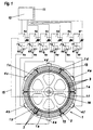
- the electric motor shown in Fig. 1 has an overall designated 1 stationary ring-shaped stator with wound stator poles for generating a Rotating field.
- a rotatably mounted rotor 2 which with Permanent magnets with alternating polarity, distributed in a ring over its circumference are provided.
- These permanent magnets are designated by the reference number 3 and can for example be made of ferrite material, samarium-cobalt material or Iron neodymium material.
- the stator 1 now consists of several separate ones Stator segments 1a, 1b, 1c, 1d, 1e and 1f, each with its own power connections 4a to 4f.
- the power connections and the lines are only schematic here shown.
- a supply with three-phase current one becomes per stator segment 1a to 1f
- a three-phase supply line and a three-phase discharge line as they do can be seen, for example, from the winding diagram of FIG. 3.
- the derivation can internally combined to form a star point (optional).
- each stator segment can essentially be its own, preferably permanently excited synchronous machine correspond to each stator segment is designed with multiple poles and the winding lines in series or in parallel at least two poles are guided to total the desired rotating field produce.
- each stator segment 1a to 1f is above the respective one Power connections 4a to 4f fed by their own frequency converter 5a to 5f, each frequency converter having a control part 6a to 6f in a manner known per se and has a power section 7a to 7f.
- the control parts 6a to 6f are in the sense of a Master-slave function interconnected, the control part 6a Master role takes over. If 6a fails, each of the control parts 6b to 6f can Take over the master function again so that the redundancy is optimal.
- the Power sections 7a to 7f are independent of each other and only of their own Control part 6a to 6f driven to the current to the individual stator segments 1a to 1f to deliver.
- stator segment 1a to 1f or the associated frequency converter fails 5a to 5f, the electric motor remains fully operational, which is particularly important when used Cable car facilities is of great importance. Only the torque or Power output reduced according to the failure of the respective part.
- contactors 8a to 8f installed, for example depending on a current detection device 9a to 9f are controlled such that at Breakdown of the current the respective contactor opens immediately.
- This Current detection device 9a to 9f is part of a monitoring electronics that for example on the display panel of a main control device 10 via displays 11 can inform staff which stator segment has failed.
- control part 6a (master) desired engine parameters (such as the speed).
- desired engine parameters such as the speed.
- the Structure of the frequency converter can essentially contribute to the state of the art correspond to permanently excited synchronous machines.
- resolver 14 also belongs to the prior art (Angle of rotation encoder), which detects the angular position of the rotor 2 and a Resolver effet 15 passes on to the master converter 6a.
- Electric motor is not only - as described above - divided electrically into segments, but that the stator segments also mechanically as separate modular Modules are designed that are independent of each other on a stator support 12 are releasably attachable, for example via schematically shown Screw connections 13. This makes it possible to modular the electric motor on site build up and in the event of failure of a stator segment this quickly and easily exchange.
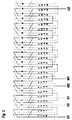
- FIG. 2 shows a winding diagram of a 16-pole permanently excited Synchronous machine according to the prior art, so that the stator is not in Segments is divided.
- FIG. 3 shows a winding diagram of a 4 ⁇ 4-pole machine according to the invention, which has four stator segments. You can see that after 4 poles no winding lines go on, but these can be brought out. One can therefore wire the individual stator segments with 4 poles each independently and preferably - as mentioned above - also separate mechanically modular.
- the 3 has several crossing points, but allows that segmented or modular structure according to the invention.
- Fig. 4 shows the use of an electric motor according to the invention for driving a Pulley 16, in the groove of which a conveyor cable 17 is guided.
- the pulley 16 is directly rotatably connected to the rotor 2 of the electric motor, which at its Circumferential surface carries permanent magnets 3 of alternating polarity. Basically would be it is also conceivable to use electromagnets instead of the permanent magnets 3 here.
- the rotor 2 is rotatably supported in a support 19 in bearings 18.
- the stator is off individual stator segments constructed, for example six, as in Fig. 1. This Stator segments, of which only two, namely 1a and 1d, are visible are over Screw connections 13 connected to a fixed support 12.
- constructive solutions are also conceivable in which the stator inside and the rotor outside.
- the pulley can preferably (but not exclusively) a rope of a cable car or other climbing aid, such as for example, chairlift or drag lift.
Landscapes
- Engineering & Computer Science (AREA)
- Power Engineering (AREA)
- Transportation (AREA)
- Mechanical Engineering (AREA)
- Permanent Magnet Type Synchronous Machine (AREA)
- Control Of Ac Motors In General (AREA)
- Iron Core Of Rotating Electric Machines (AREA)
- Windings For Motors And Generators (AREA)
- Permanent Field Magnets Of Synchronous Machinery (AREA)
- Insulation, Fastening Of Motor, Generator Windings (AREA)
Applications Claiming Priority (2)
| Application Number | Priority Date | Filing Date | Title |
|---|---|---|---|
| AT171999 | 1999-10-11 | ||
| AT171999 | 1999-10-11 |
Publications (2)
| Publication Number | Publication Date |
|---|---|
| EP1093207A2 true EP1093207A2 (fr) | 2001-04-18 |
| EP1093207A3 EP1093207A3 (fr) | 2006-02-01 |
Family
ID=3519532
Family Applications (1)
| Application Number | Title | Priority Date | Filing Date |
|---|---|---|---|
| EP00121421A Withdrawn EP1093207A3 (fr) | 1999-10-11 | 2000-09-29 | Moteur électrique |
Country Status (7)
| Country | Link |
|---|---|
| US (1) | US6429554B1 (fr) |
| EP (1) | EP1093207A3 (fr) |
| JP (1) | JP2001169520A (fr) |
| CN (1) | CN100369366C (fr) |
| AT (1) | AT6706U1 (fr) |
| AU (1) | AU6410900A (fr) |
| CA (1) | CA2322923A1 (fr) |
Cited By (8)
| Publication number | Priority date | Publication date | Assignee | Title |
|---|---|---|---|---|
| EP1172322A1 (fr) * | 2000-07-14 | 2002-01-16 | Miguel Manuel Zarraga Valpuesta | Système d'actionnement pour enrouleurs de cable |
| EP1343246A3 (fr) * | 2002-03-07 | 2004-02-04 | Innova Patent GmbH | Circuit pour l'alimentation d'un moteur électrique |
| EP1521356A2 (fr) | 2003-09-30 | 2005-04-06 | Vacon Oyj | Contrôle des convertisseurs ou invertisseurs de fréquence opérés en parallèle |
| WO2007000403A1 (fr) * | 2005-06-27 | 2007-01-04 | Siemens Aktiengesellschaft | Entrainement direct pour entrainements de gros volume |
| EP2164154A1 (fr) * | 2008-09-15 | 2010-03-17 | Siemens Aktiengesellschaft | Agencement de stator, générateur et éolienne |
| WO2012059110A3 (fr) * | 2010-11-05 | 2012-08-23 | Vestas Wind Systems A/S | Générateur segmenté à entraînement direct |
| CN102790452A (zh) * | 2012-08-30 | 2012-11-21 | 徐志瑶 | 多层次额定频率结构且规格化系列化的变频驱动电机及其设计方法 |
| EP2276149A3 (fr) * | 2009-07-13 | 2016-11-09 | Siemens Aktiengesellschaft | Schéma d'enroulement pour un support segmenté d'une machine dynamoélectrique |
Families Citing this family (14)
| Publication number | Priority date | Publication date | Assignee | Title |
|---|---|---|---|---|
| DE10210071A1 (de) * | 2002-03-08 | 2003-10-09 | Lat Suhl Ag | Drehmomentmotor in Segmentbauweise |
| EP1460022A1 (fr) * | 2003-03-20 | 2004-09-22 | Inventio Ag | Treuil pour ascenseur |
| WO2008033093A1 (fr) * | 2006-09-11 | 2008-03-20 | Yi Min Amane Chu | Micromoteur sans bobinage (mcm) |
| DE102009051939A1 (de) * | 2009-11-04 | 2011-05-05 | Dieffenbacher Gmbh + Co. Kg | Presse mit einem direkt angetriebenen Kurbeltrieb, Pressenstraße aus derartigen Pressen und ein Verfahren zur Herstellung einer Presse mit zumindest einem Direktantrieb. |
| JP5455736B2 (ja) * | 2010-03-25 | 2014-03-26 | 日本ケーブル株式会社 | 索道の原動機 |
| EP2481701A1 (fr) * | 2011-01-31 | 2012-08-01 | Siemens Aktiengesellschaft | Dispositif de levage pour grue à conteneur et grue à conteneur |
| JP2014519297A (ja) * | 2011-04-04 | 2014-08-07 | エフ・エル・スミス・エー・エス | ヘビーデューティミル |
| US10143427B2 (en) | 2016-01-27 | 2018-12-04 | General Electric Company | Segmented direct drive motor for use in a computed tomography system |
| DE102017216818A1 (de) * | 2017-09-22 | 2019-03-28 | Siemens Aktiengesellschaft | Azimutverstellung einer Gondel |
| EP3540924B1 (fr) * | 2018-03-12 | 2023-10-18 | ABB Schweiz AG | Commande et entraînement d'une machine tournante comprenant un stator interne et externe |
| CN108545085A (zh) * | 2018-04-19 | 2018-09-18 | 娄底市同丰科技有限公司 | 一种矿用乘人装置 |
| CN108512334B (zh) * | 2018-04-24 | 2024-07-30 | 北京金风科创风电设备有限公司 | 模块化定子及风力发电机组 |
| CN110176340A (zh) * | 2019-06-28 | 2019-08-27 | 岑凯军 | 一种组合磁体、永磁体磁能转化装置及转化装置控制方法 |
| CN112737164B (zh) * | 2020-12-24 | 2024-03-29 | 中国航空工业集团公司金城南京机电液压工程研究中心 | 一种旋转变压器及嵌线方法 |
Family Cites Families (16)
| Publication number | Priority date | Publication date | Assignee | Title |
|---|---|---|---|---|
| US2993134A (en) * | 1957-01-02 | 1961-07-18 | Gen Electric | Permanent magnet motor |
| US3603866A (en) * | 1970-03-24 | 1971-09-07 | Kenneth E Opal | Energizing system with digital control circuit for regulating multiphase inverter |
| US3911765A (en) * | 1970-10-26 | 1975-10-14 | Heron Poma Company | Ski lift bullwheel |
| US4177414A (en) * | 1977-12-21 | 1979-12-04 | Precise Power Corporation | Controllable voltage A.C. generator system |
| US4434389A (en) * | 1980-10-28 | 1984-02-28 | Kollmorgen Technologies Corporation | Motor with redundant windings |
| CA1167147A (fr) | 1981-09-02 | 1984-05-08 | Thomas M. Jahns | Systeme propulseur d'embarcation |
| US4550267A (en) * | 1983-02-18 | 1985-10-29 | Sundstrand Corporation | Redundant multiple channel electric motors and generators |
| DE3642724A1 (de) * | 1986-12-13 | 1988-06-23 | Grundfos Int | Elektromotor mit einem frequenzumrichter zur steuerung der motorbetriebsgroessen |
| US5015903A (en) | 1988-08-15 | 1991-05-14 | Pacific Scientific Company | Electronically commutated reluctance motor |
| DE4014848A1 (de) | 1990-05-09 | 1991-11-14 | Magnet Bahn Gmbh | Verfahren zur stromlosen umschaltung von speiseabschnitten von langstatormotoren bei versorgung aus einem frequenzumrichter |
| DE4136119C2 (de) * | 1991-11-02 | 1994-03-17 | Erno Raumfahrttechnik Gmbh | Linearantrieb |
| US5760507A (en) * | 1996-02-06 | 1998-06-02 | Ford Global Technologies, Inc. | Electrical generating system for a motor vehicle |
| DE19620442A1 (de) * | 1996-05-21 | 1997-11-27 | Siemens Ag | Unrichtersystem |
| US5912522A (en) * | 1996-08-22 | 1999-06-15 | Rivera; Nicholas N. | Permanent magnet direct current (PMDC) machine with integral reconfigurable winding control |
| DE19704769C2 (de) * | 1997-02-08 | 1999-06-10 | Weh Herbert Prof Dr Ing Dr H C | Mehrsträngige Synchronmaschine mit Permanentmagneten und Spulenmodulen |
| US6150731A (en) * | 1999-02-16 | 2000-11-21 | Electric Boat Corporation | Integrated high frequency marine power distribution arrangement with transformerless high voltage variable speed drive |
-
1999
- 1999-10-11 AT AT0810002U patent/AT6706U1/de not_active IP Right Cessation
-
2000
- 2000-09-29 EP EP00121421A patent/EP1093207A3/fr not_active Withdrawn
- 2000-10-05 JP JP2000305909A patent/JP2001169520A/ja active Pending
- 2000-10-09 AU AU64109/00A patent/AU6410900A/en not_active Abandoned
- 2000-10-10 CN CNB001306626A patent/CN100369366C/zh not_active Expired - Fee Related
- 2000-10-10 US US09/685,910 patent/US6429554B1/en not_active Expired - Lifetime
- 2000-10-10 CA CA002322923A patent/CA2322923A1/fr not_active Abandoned
Non-Patent Citations (1)
| Title |
|---|
| None |
Cited By (15)
| Publication number | Priority date | Publication date | Assignee | Title |
|---|---|---|---|---|
| EP1172322A1 (fr) * | 2000-07-14 | 2002-01-16 | Miguel Manuel Zarraga Valpuesta | Système d'actionnement pour enrouleurs de cable |
| ES2166722A1 (es) * | 2000-07-14 | 2002-04-16 | Valpuesta Miguel Manue Zarraga | Sistema de accionamiento para arrolladores de cable. |
| EP1343246A3 (fr) * | 2002-03-07 | 2004-02-04 | Innova Patent GmbH | Circuit pour l'alimentation d'un moteur électrique |
| EP1521356A2 (fr) | 2003-09-30 | 2005-04-06 | Vacon Oyj | Contrôle des convertisseurs ou invertisseurs de fréquence opérés en parallèle |
| US7816832B2 (en) | 2005-06-27 | 2010-10-19 | Siemens Aktiengesellschaft | Direct drive for large-scale drives |
| WO2007000403A1 (fr) * | 2005-06-27 | 2007-01-04 | Siemens Aktiengesellschaft | Entrainement direct pour entrainements de gros volume |
| EP2164154A1 (fr) * | 2008-09-15 | 2010-03-17 | Siemens Aktiengesellschaft | Agencement de stator, générateur et éolienne |
| US8274191B2 (en) | 2008-09-15 | 2012-09-25 | Siemens Akteingesellschaft | Stator arrangement, generator and wind turbine |
| EP2276149A3 (fr) * | 2009-07-13 | 2016-11-09 | Siemens Aktiengesellschaft | Schéma d'enroulement pour un support segmenté d'une machine dynamoélectrique |
| WO2012059110A3 (fr) * | 2010-11-05 | 2012-08-23 | Vestas Wind Systems A/S | Générateur segmenté à entraînement direct |
| WO2012059111A3 (fr) * | 2010-11-05 | 2012-08-23 | Vestas Wind Systems A/S | Générateur segmenté à entraînement direct |
| US9455603B2 (en) | 2010-11-05 | 2016-09-27 | Vestas Wind Systems A/S | Direct drive segmented generator |
| US9660493B2 (en) | 2010-11-05 | 2017-05-23 | Vestas Wind System A/S | Direct drive segmented generator |
| CN102790452A (zh) * | 2012-08-30 | 2012-11-21 | 徐志瑶 | 多层次额定频率结构且规格化系列化的变频驱动电机及其设计方法 |
| CN102790452B (zh) * | 2012-08-30 | 2014-04-16 | 徐志瑶 | 多层次额定频率结构且规格化系列化的变频驱动电机及其设计方法 |
Also Published As
| Publication number | Publication date |
|---|---|
| AT6706U1 (de) | 2004-02-25 |
| EP1093207A3 (fr) | 2006-02-01 |
| AU6410900A (en) | 2001-04-12 |
| CA2322923A1 (fr) | 2001-04-11 |
| US6429554B1 (en) | 2002-08-06 |
| JP2001169520A (ja) | 2001-06-22 |
| CN100369366C (zh) | 2008-02-13 |
| CN1292597A (zh) | 2001-04-25 |
Similar Documents
| Publication | Publication Date | Title |
|---|---|---|
| EP1093207A2 (fr) | Moteur électrique | |
| EP0785162B1 (fr) | Système d'entraínement pour ascenseur | |
| AT408210B (de) | Elektrischer antrieb für ein fahrzeug | |
| EP1050437B1 (fr) | Direction pour un véhicule automobile | |
| EP3595149A1 (fr) | Système d'entraînement de moteur linéaire | |
| DE3429098A1 (de) | Kran und kranantriebseinrichtung | |
| DE19533740C2 (de) | Lasthebemagneteinrichtung | |
| WO2014101910A2 (fr) | Dispositif d'entraînement pour l'accouplement pivotant d'un élément d'une installation ou d'une machine | |
| DE19726351A1 (de) | Magnetgelagerter elektrischer Antrieb mit integriertem Wicklungssystem | |
| EP1726084A1 (fr) | Train a sustentation magnetique presentant un dispositif a transmission d'energie inductive, sans contact, d'une voie de circulation a un vehicule a sustentation magnetique | |
| EP1940007A1 (fr) | Agencement d'enroulement de stator pour un moteur synchrone doté d'un couple de freinage réduit en cas d'erreur | |
| DE19726352A1 (de) | Magnetgelagerter elektrischer Antrieb mit konzentrierten Wicklungen | |
| EP0597365B2 (fr) | Pompe à vide avec convertisseur | |
| EP1725422A1 (fr) | Ensemble magnetique pour un vehicule a sustentation magnetique | |
| WO2005090115A1 (fr) | Systeme magnetique conçu pour un vehicule a sustentation magnetique | |
| DE19718840C1 (de) | Antriebsmittel für eine Linearbewegung, insbesondere kontinuierliche Linearbewegung und Langstator-Linearmotor | |
| DE102010029370A1 (de) | U-Boot-Propulsionsantriebssystem | |
| WO2012059535A1 (fr) | Palier à roulement à entraînement direct | |
| DE907551C (de) | Anordnung zur Steuerung von Elektromotoren | |
| EP2667496A2 (fr) | Chariot de manutention présentant un moteur de pompe électrique | |
| EP1688576B1 (fr) | Porte coulissante avec système d'entraînement magnétique et fonctionnalité de voie d'evacuation | |
| EP4287468A1 (fr) | Système de moteur électrique | |
| DE2921860C2 (de) | Einrichtung zur Ortung und Steuerung eines spurgebundenen Fahrzeuges mit Linearmotorantrieb | |
| EP0299137A1 (fr) | Entraînement électrique ou générateur | |
| EP4287467A1 (fr) | Système de moteur électrique |
Legal Events
| Date | Code | Title | Description |
|---|---|---|---|
| PUAI | Public reference made under article 153(3) epc to a published international application that has entered the european phase |
Free format text: ORIGINAL CODE: 0009012 |
|
| AK | Designated contracting states |
Kind code of ref document: A2 Designated state(s): AT BE CH CY DE DK ES FI FR GB GR IE IT LI LU MC NL PT SE |
|
| AX | Request for extension of the european patent |
Free format text: AL;LT;LV;MK;RO;SI |
|
| RIN1 | Information on inventor provided before grant (corrected) |
Inventor name: FUCHS,ELMER Inventor name: ALBRICH, REINHARD |
|
| PUAL | Search report despatched |
Free format text: ORIGINAL CODE: 0009013 |
|
| AK | Designated contracting states |
Kind code of ref document: A3 Designated state(s): AT BE CH CY DE DK ES FI FR GB GR IE IT LI LU MC NL PT SE |
|
| AX | Request for extension of the european patent |
Extension state: AL LT LV MK RO SI |
|
| RIC1 | Information provided on ipc code assigned before grant |
Ipc: B61B 11/00 20060101ALI20051213BHEP Ipc: H02K 16/04 20060101ALI20051213BHEP Ipc: H02P 6/00 20060101AFI20051213BHEP |
|
| 17P | Request for examination filed |
Effective date: 20060712 |
|
| 17Q | First examination report despatched |
Effective date: 20060825 |
|
| AKX | Designation fees paid |
Designated state(s): AT BE CH CY DE DK ES FI FR GB GR IE IT LI LU MC NL PT SE |
|
| STAA | Information on the status of an ep patent application or granted ep patent |
Free format text: STATUS: THE APPLICATION IS DEEMED TO BE WITHDRAWN |
|
| 18D | Application deemed to be withdrawn |
Effective date: 20070306 |