EP1093274A2 - Structure de charnière pour un téléphone portable et pliable - Google Patents
Structure de charnière pour un téléphone portable et pliable Download PDFInfo
- Publication number
- EP1093274A2 EP1093274A2 EP00119328A EP00119328A EP1093274A2 EP 1093274 A2 EP1093274 A2 EP 1093274A2 EP 00119328 A EP00119328 A EP 00119328A EP 00119328 A EP00119328 A EP 00119328A EP 1093274 A2 EP1093274 A2 EP 1093274A2
- Authority
- EP
- European Patent Office
- Prior art keywords
- display member
- rotary shaft
- biasing force
- display
- rotated
- Prior art date
- Legal status (The legal status is an assumption and is not a legal conclusion. Google has not performed a legal analysis and makes no representation as to the accuracy of the status listed.)
- Granted
Links
- 230000000694 effects Effects 0.000 claims description 8
- 229920003002 synthetic resin Polymers 0.000 claims description 8
- 239000000057 synthetic resin Substances 0.000 claims description 8
- 238000013016 damping Methods 0.000 claims description 7
- 230000000881 depressing effect Effects 0.000 claims description 4
- 239000002184 metal Substances 0.000 description 4
- 238000004512 die casting Methods 0.000 description 2
- 238000009434 installation Methods 0.000 description 2
- 230000000994 depressogenic effect Effects 0.000 description 1
- 239000004973 liquid crystal related substance Substances 0.000 description 1
- 230000007257 malfunction Effects 0.000 description 1
- 238000004519 manufacturing process Methods 0.000 description 1
Images

Classifications
-
- H—ELECTRICITY
- H04—ELECTRIC COMMUNICATION TECHNIQUE
- H04B—TRANSMISSION
- H04B1/00—Details of transmission systems, not covered by a single one of groups H04B3/00 - H04B13/00; Details of transmission systems not characterised by the medium used for transmission
- H04B1/38—Transceivers, i.e. devices in which transmitter and receiver form a structural unit and in which at least one part is used for functions of transmitting and receiving
-
- H—ELECTRICITY
- H04—ELECTRIC COMMUNICATION TECHNIQUE
- H04M—TELEPHONIC COMMUNICATION
- H04M1/00—Substation equipment, e.g. for use by subscribers
- H04M1/02—Constructional features of telephone sets
- H04M1/0202—Portable telephone sets, e.g. cordless phones, mobile phones or bar type handsets
- H04M1/0206—Portable telephones comprising a plurality of mechanically joined movable body parts, e.g. hinged housings
- H04M1/0208—Portable telephones comprising a plurality of mechanically joined movable body parts, e.g. hinged housings characterized by the relative motions of the body parts
- H04M1/0214—Foldable telephones, i.e. with body parts pivoting to an open position around an axis parallel to the plane they define in closed position
- H04M1/0216—Foldable in one direction, i.e. using a one degree of freedom hinge
Definitions
- the present invention relates to a hinge structure for a collapsible portable phone.
- a collapsible portable phone composed of an operating body provided with a phone operating portion on its surface and a display body pivotally and collapsibly coupled with the operating body and provided with a liquid crystal display image field that may display Arabic numerals or letters such as names or phone numbers on its surface.
- this type portable phone be collapsed to be superior in portability and a malfunction of the phone operating portion may be prevented when the phone operating portion is protected or concealed in the case where the portable phone is put into a pocket in the collapsed condition.
- this structure has an advantage that the user may enjoy the conversation comfortably because the overall length is elongated when opened. In some cases, the user would feel uncomfortable unless a microphone portion is close to his or her mouth.
- the present inventors have paid his attention to this type collapsible portable phone and have invented a hinge structure for a novel collapsible portable phone that is extremely convenient in use, extremely high in commercial applicability, and may cultivate or motivate the consumers' heart to buy.
- a hinge structure for a collapsible portable phone comprising: an operating member provided with a phone operating portion on its surface; a display member, pivotally and collapsibly coupled with the operating member and provided with a display image field in which numerals and/or letters for phone numbers and/or names may be displayed on its surface; and a biasing mechanism that may exhibit a closing biasing force for biasing the display member in a closing direction between a closed condition that the display member is collapsed to the operating member and a predetermined rotational position where the display member is rotated to the operating member in an opening direction and may exhibit an opening biasing force for biasing the display member in the opening direction between a fully opened condition that the display member is fully opened to the operating member and a predetermined rotational position where the display member is rotated in the closing direction, the biasing mechanism being provided at a pivot portion between the operating member and the display member, wherein a rotary shaft coupled with the operating member is provided, a bearing
- a hinge structure for a collapsible portable phone comprising: an operating member provided with a phone operating portion on its surface; a display member, pivotally and collapsibly coupled with the operating member and provided with a display image field in which numerals and/or letters for phone numbers and/or names may be displayed on its surface; and a biasing mechanism that may exhibit a closing biasing force for biasing the display member in a closing direction between a closed condition that the display member is collapsed to the operating member and a predetermined rotational position where the display member is rotated to the operating member in an opening direction and may exhibit an opening biasing force for biasing the display member in the opening direction between a fully opened condition that the display member is fully opened to the operating member and a predetermined rotational position where the display member is rotated in the closing direction, the biasing mechanism being provided at a pivot portion between the operating member and the display member, wherein a rotary shaft coupled with the operating member is provided, a bearing member
- a hinge structure for a collapsible portable phone comprising: an operating member provided with a phone operating portion on its surface; a display member, pivotally and collapsibly coupled with the operating member and provided with a display image field in which numerals and/or letters for phone numbers and/or names may be displayed on its surface; and a biasing mechanism that may exhibit a closing biasing force for biasing the display member in a closing direction between a closed condition that the display member is collapsed to the operating member and a predetermined rotational position where the display member is rotated to the operating member in an opening direction and may exhibit an opening biasing force for biasing the display member in the opening direction between a fully opened condition that the display member is fully opened to the operating member and a predetermined rotational position where the display member is rotated in the closing direction, the biasing mechanism being provided at a pivot portion between the operating member and the display member, wherein a rotary shaft coupled with the display member is provided, a bearing member provided with
- a hinge structure for a collapsible portable phone comprising: an operating member provided with a phone operating portion on its surface; a display member, pivotally and collapsibly coupled with the operating member and provided with a display image field in which numerals and/or letters for phone numbers and/or names may be displayed on its surface; and a biasing mechanism that may exhibit a closing biasing force for biasing the display member in a closing direction between a closed condition that the display member is collapsed to the operating member and a predetermined rotational position where the display member is rotated to the operating member in an opening direction and may exhibit an opening biasing force for biasing the display member in the opening direction between a fully opened condition that the display member is fully opened to the operating member and a predetermined rotational position where the display member is rotated in the closing direction, the biasing mechanism being provided at a pivot portion between the operating member and the display member, wherein a rotary shaft coupled with the display member is provided, a bearing member provided with
- a biasing member for depressing and biasing the bearing member to the rotary shaft is provided, and the depressing and biasing force of the biasing member causes a damping effect due to a contact resistance between the rotary shaft and the bearing member when the display member is rotated relative to the operating member between the predetermined rotational positions to serve as a holding force for holding the opened condition of the display member to the operating member.
- an engagement portion that engages with the bearing member in the rotary shaft and the bearing member are made of suitable synthetic resin.
- an engagement portion that engages with the bearing member in the rotary shaft and the bearing member are made of suitable synthetic resin
- the display member is rotated in the opening direction until the display member is biased by the opening biasing force of the biasing mechanism up to the maximum opening state when the display member is rotated in the opening direction up to a predetermined rotational position from the collapsed condition.
- the opening biasing force of the biasing mechanism since the opening biasing force of the biasing mechanism is applied always to the display member, for instance, there is no fear that the display member is accidentally closed when the user enjoys the conversation, and the opened condition of the display member may be held always.
- the display member when the display member is rotated in the closing direction to the operating member to the predetermined position A from the fully opened condition, the display member is biased by the closing biasing force of the biasing mechanism and rotated in the closing direction to the closed condition.
- the closing biasing force of the biasing mechanism since the closing biasing force of the biasing mechanism is always applied to the display member, for instance, there is no fear that the display member is accidentally opened, and the display member is always kept under the closed condition.
- the rotational biasing force of the biasing mechanism S which will become the closing biasing force for biasing the display member to the operating member in the closing direction and the opening biasing force for biasing the display member to the operating member in the opening direction, is composed of a force for engaging the recess portion or the elongate portion provided in the rotary shaft with the elongate portion or the recess portion provided in the bearing member from the disengaged condition. Accordingly, even with a miniaturized size, it is possible to exhibit the good rotational biasing force without fail, and hence it is possible to attain the miniaturization and reduction of weight of the portable phone as a whole.
- the contact between the convex portion and the concave portion is a point contact. Accordingly, it is necessary to provide the contact between the convex portion and the concave portion away from the axis of the rotary shaft by increasing the size of the projection (the diameter) or the like in order to obtain the sufficient biasing force by the cam effect. As a result the hinge portion provided with the biasing mechanism composed of this rotary shaft and the bearing member is enlarged in size, and hence, the weight of the portable phone as a whole is increased and the size thereof is also enlarged.
- the contact between the recess portion and the elongate portion of the rotary shaft and the bearing member is the line contact (or the area contact). Accordingly, it is possible to obtain the wide surface area even with the small size projection and to exhibit the sufficient rotational biasing force even if the projection is provided in the vicinity of the axis of the rotary shaft. It is therefore possible to make very compact the hinge portion provided with the biasing mechanism composed of the rotary shaft and the bearing member. Thus, it goes without saying that it is possible to produce the phones in low cost in a mass-production fashion. In addition, it is possible to attain the miniaturization and the reduction in weight of the portable phones as a whole.
- the third aspect of the invention it goes without saying that it is possible to provide the portable phones in low cost in excellent productivity. In addition, it is possible to attain the miniaturization and reduction in weight of the portable phones as a whole in a more effective way.
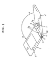
- a collapsible portable phone is composed of an operating member 2 provided at its surface with a phone operating portion 1, and a display member 3 pivotally and collapsibly mounted on the operating member 2 and provided with a display surface 6 that may display Arabic numerals or letters such as phone numbers or names on its surface.
- a biasing mechanism S is interposed in a hinge portion 4 between the operating member 2 and the display member 3, which biasing mechanism may exhibit a closing biasing force for biasing the display member 3 in a closing direction between a closed condition in which the display member 3 is collapsed relative to the operating member 2 and a predetermined angular position A in which the display member 3 is angularly moved in an opening direction, and may exhibit an opening biasing force for biasing the display member 3 in an opening direction between the opened condition in which the display member 3 is fully opened relative to the operating member 2 and a predetermined angular position B in which the display member 3 is angularly moved in the closing direction.
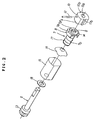
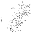
- the biasing mechanism S is composed of a biasing member 11 composed of a rotary shaft 5 and a bearing member 7 formed together with the rotary member 5.
- the rotary shaft 5 of the biasing member 11 is formed of a rod-like member made of suitable metal.
- This rotary shaft 5 is fitted in a ring member 10 made of suitable synthetic resin at its end portion in a rotation-preventing manner through a retainer pin 12.
- a pair of elongated projections 9 are formed radially in a position, facing an opening of a through-hole 10a through which the rotary shaft 5 passes, of the inner surface of this ring member 10.
- a member obtained by pressing a member made of suitable metal or by die-casting may be used as the ring member 10.
- the latter is extremely superior in durability. This has been confirmed experimentally by the present applicant.
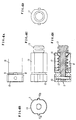
- the elongate projections 9 are formed so as to fit elongate recesses 8 formed in the bearing member 7 to be described later in detail. Each corner portion forming the elongate projections 9 are rounded or beveled.
- elongate projections 10b are formed on right and left side wall cut into flat surfaces for the circumferential surfaces of the ring member 10.
- the elongate projections 10b are used to couple the rotary shaft 5 with the operating member 2 or the display member 3 in a rotation preventing manner.
- This ring member 10 may also be referred to as an engagement portion of the rotary shaft 5.
- a circumferential flange 13 is formed at a proximal end portion of the rotary shaft 5. This circumferential flange 13 is used to couple the rotary shaft 5 to be rotatable relative to a receptacle 15 for receiving the bearing member 7 to be described later in detail.
- the bearing member 7 is formed of a member made of suitable synthetic resin.
- the bearing member 7 is composed of a bearing portion 7a having a substantially square shape as viewed from the front side so as to be fit in a rotation preventing fashion and a cylindrical portion 7b formed integrally with the bearing portion 7a and that may fit in the rotary shaft 5.
- a member made of suitable metal may be used as the bearing member 7 in conformity with the above-described ring member 10.
- the latter is extremely superior in durability. This has been confirmed experimentally by the present applicant.
- an axial hole 7a' is formed in the bearing portion 7a. This axial hole 7a' is formed so that the rotary shaft 5 may pass through the axial hole 7a'.
- a pair of annular projections 14 are formed on an opening circumferential edge of the tip end face of the axial hole 7a' of the bearing portion 7a.
- the annular projections 14 define the pair of recess portions 8 by being cut at two diametrically opposite positions.
- the recess portions 8 are formed so as to be fitted with the elongate projections 9 formed on the ring member 7a engaged with the rotary shaft 5 when the bearing member 7 and the rotary shaft 5 are coupled with each other.
- Each corner portion forming the recess portions 8 are rounded or beveled.
- the bearing member 7 is received in the receptacle 15 made of metal and having a substantially square-shape as viewed from the front side.
- the bearing member 7 is coupled with the rotary member 5 to form the above-described biasing member 11.
- a leaf spring 16 is disposed within the receptacle 15, and a coiled spring 17 is fitted around the cylindrical portion 7b of the bearing member 7.
- the rotary shaft 5 is caused to pass through the receptacle 15 and the bearing member 7 via a washer 18.
- the ring member 10 is fitted and coupled at the tip end portion of the rotary shaft 5.
- the rotary shaft 5 is rotatable relative to the bearing member 7 and the receptacle 15.
- the bearing member 7 is movable in the axial direction (direction indicated by character a in Fig.
- the thus constructed biasing member 11 is constructed so that the condition where the rotary shaft 5 and the bearing member 7 are disengaged from each other is likely to come to the condition where these components are engaged with each other, whereby a rotational biasing force for forcibly rotating the rotary shaft 5 is generated twice.
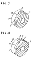
- the elongate projections 9 are likely to be slid in a direction indicated by an arrow c in Fig. 6 and engaged with the recess portions 8 from the condition that the elongate projections 9 are disengaged from the recess portions 8 by a contact relationship between the rounded surfaces of the elongate projections 9 and the recess portions 8 and the depression biasing force of the leaf spring 16 and the coiled spring 17, so that a first rotational biasing force is effected in the rotary shaft 5.
- the elongate projections 9 are provided on the rotary shaft 5 and the recess portions 8 are provided in the bearing member 7.
- the respective ring members 10 of the shaft 5 are fitted in the rotation preventing condition with installation portions 2a provided at right and left positions on the tip end sides of the operating member 2, whereas the respective receptacles 15 receiving the bearing members 7 are fitted in the rotation preventing condition with installation portions 3a provided at right and left positions on the proximal end side of the display member 3. Accordingly, the display member 3 is pivoted to the operating member 2 through the biasing member 11. Incidentally, it is possible to provide the rotary shaft 5 to the display member 3 and to provide the bearing member 7 to the operating member 2.
- one of the rotational biasing forces generated whenever the rotary shaft 5 is rotated around the axis by 180° is applied as the closing biasing force for biasing the display member 3 in the closing direction, and the other is applied as the opening biasing force for biasing the display member 3 in the opening direction.
- the biasing mechanism may exhibit a closing biasing force for biasing the display member 3 in a closing direction between a closed condition in which the display member 3 is collapsed relative to the operating member 2 and a predetermined angular position A in which the display member 3 is angularly moved in an opening direction, and may exhibit an opening biasing force for biasing the display member 3 in an opening direction between the opened condition in which the display member 3 is fully opened relative to the operating member 2 and a predetermined angular position B in which the display member 3 is angularly moved in the closing direction.
- the closing biasing force is applied so as to prevent the display member 3 from being opened accidentally
- the opening biasing force is applied so as to prevent the display member 3 from being closed in case of, for example, conversation.
- the elongate projections 9 provided on the rotary shaft 5 and the recess portions 8 provided in the bearing member 7 are set so as to be disengaged from each other so that any rotational biasing force is not applied and the end faces of the annular projections 14 of the bearing member 7 are always depressed against the elongate projections 9 of the rotary shaft 5 by the leaf spring 16 and the coiled spring 17 used as the biasing members when the display member 3 is rotated relative to the above-described operating member 2 between the above-described predetermined rotational position A and the above-described predetermined rotational position B.
- the damping effect is caused by the contact resistance is generated, so that the depression biasing force of the leaf spring 16 and the coiled spring 17 is used as the holding force for holding the opened condition of the display member 3 relative to the operating member 2. Accordingly, the display member 3 is held in the stop condition (slanted condition) at a desired position relative to the operating member 2 by the above-described damping effect when the display member 3 is rotated between this predetermined rotational position A and the above-described predetermined rotational position B.
- the rotational biasing force (closing biasing force) of the biasing mechanism S further works in the closing direction even in the collapsed closed condition of the display member 3 to the operating member 2.
- the present embodiment is set so that the opened condition (condition shown in Fig. 1) where the display member 3 is fully opened is obtained when the display member 3 is rotated by about 150° to 160° relative to the operating member 2. Accordingly, when the biasing member 11 is assembled with the hinge portion 4, the components are assembled so that the rotational biasing force is left in a predetermined range such that the closing biasing force is further applied even if the display member 3 is kept in the collapsed closed condition relative to the operating member 2 out of the range where the rotational biasing force generated by rotating the rotary shaft 5 about the axis is applied.
- the display member 3 when the display member 3 is rotated in the opening direction from the collapsed closed condition to the predetermined rotational position B relative to the operating member 2, the display member 3 is biased by the opening biasing force of the biasing mechanism S and rotated in the opening direction until it is fully opened.
- the opening biasing force of the biasing mechanism S since the opening biasing force of the biasing mechanism S is always applied to the display member 3. Accordingly, there is no trouble such as a case, for example, where the display member 3 is closed when the user enjoys his or her conversation and so on.
- the display member 3 is always kept in the opened condition.
- the display member 3 when the display member 3 is rotated in the closing direction from the fully opened condition of the display member 3 to the predetermined rotational position A relative to the operating member 2, the display member 3 is biased by the closing biasing force of the biasing mechanism S and rotated in the closing direction until it is fully closed.
- the closing biasing force of the biasing mechanism S since the closing biasing force of the biasing mechanism S is always applied to the display member 3. Accordingly, there is no trouble such as a case, for example, where the display member 3 is opened accidentally.
- the display member 3 is always kept in the closed condition.
- the rotational biasing force of the biasing mechanism S which will become the closing biasing force for biasing the display member 3 to the operating member 2 in the closing direction and the opening biasing force for biasing the display member 3 to the operating member 2 in the opening direction, is composed of a force for engaging the recess portion 8 or the elongate portion 9 provided in the rotary shaft 5 with the elongate portion 9 or the recess portion 8 provided in the bearing member 7 from the disengaged condition. Accordingly, even with a miniaturized size, it is possible to exhibit the good rotational biasing force without fail, and hence it is possible to attain the miniaturization and reduction of weight of the portable phone as a whole.
- the leaf spring 16 (coiled spring 17) for depressingly biasing the bearing member 7 to the rotary shaft 5 is provided so that the depression biasing force of this leaf spring 16 (coiled spring 17) causes a damping effect by the contact resistance between the rotary shaft 5 and the bearing member 7 when the display member 3 is rotated to the operating member 2 between the predetermined rotational position A and the predetermined rotational position B and is served as a holding force for holding the opened condition of the display member 3 to the operating member 2.
- the ring member 10 and the bearing member 7 of the rotary shaft 5 are made of suitable synthetic resin. Accordingly, it is possible to provide the handy portable phone that is superior in mass-productivity in low cost and in addition to more effectively attain the miniaturization and reduction in weight of the portable phone as a whole.
- the biasing member for biasing the bearing member to the rotational shaft is provided, so that the depression biasing force of this biasing member causes the damping effect to the above-described operating member due to the contact resistance between the rotary shaft and the bearing member when the display member is rotated between the above-described predetermined rotational positions to thereby serve it as the holding force for holding the display member to the operating member in the opened condition. Accordingly, it goes without saying that it is easy to simplify the structure in low cost with a high mass-productivity.
- the bearing member in the rotational shaft and the engagement portion engaging the bearing member are made of suitable synthetic resin. Accordingly, it goes without saying that it is easy to simplify the structure in low cost with a high mass-productivity.
Landscapes
- Engineering & Computer Science (AREA)
- Signal Processing (AREA)
- Computer Networks & Wireless Communication (AREA)
- Telephone Set Structure (AREA)
- Pivots And Pivotal Connections (AREA)
- Casings For Electric Apparatus (AREA)
- Mobile Radio Communication Systems (AREA)
Applications Claiming Priority (4)
| Application Number | Priority Date | Filing Date | Title |
|---|---|---|---|
| JP29355799 | 1999-10-15 | ||
| JP29355799 | 1999-10-15 | ||
| JP33768299 | 1999-11-29 | ||
| JP33768299A JP3602389B2 (ja) | 1999-10-15 | 1999-11-29 | 折り畳み携帯式電話の枢着構造 |
Publications (3)
| Publication Number | Publication Date |
|---|---|
| EP1093274A2 true EP1093274A2 (fr) | 2001-04-18 |
| EP1093274A3 EP1093274A3 (fr) | 2004-02-11 |
| EP1093274B1 EP1093274B1 (fr) | 2005-05-11 |
Family
ID=26559474
Family Applications (1)
| Application Number | Title | Priority Date | Filing Date |
|---|---|---|---|
| EP00119328A Expired - Lifetime EP1093274B1 (fr) | 1999-10-15 | 2000-09-07 | Structure de charnière pour un téléphone portable et pliable |
Country Status (5)
| Country | Link |
|---|---|
| US (1) | US6633643B1 (fr) |
| EP (1) | EP1093274B1 (fr) |
| JP (1) | JP3602389B2 (fr) |
| KR (1) | KR100439066B1 (fr) |
| DE (1) | DE60020049D1 (fr) |
Cited By (6)
| Publication number | Priority date | Publication date | Assignee | Title |
|---|---|---|---|---|
| EP1615406A1 (fr) * | 2004-07-07 | 2006-01-11 | Samsung Electronics Co., Ltd. | Dispositif de verrouillage d'un module à charnière pivotante pour terminaux de réseaux mobiles |
| CN1318769C (zh) * | 2002-02-21 | 2007-05-30 | 思嘎茨讷工业株式会社 | 铰接装置和便携式机器 |
| WO2008040832A1 (fr) * | 2006-10-06 | 2008-04-10 | Famar Muebles, S.L. | Charnière pour mobilier |
| WO2008058771A1 (fr) * | 2006-11-17 | 2008-05-22 | Sony Ericsson Mobile Communications Ab | Mécanisme d'articulation à ressort |
| CN102215650A (zh) * | 2010-04-01 | 2011-10-12 | 鸿富锦精密工业(深圳)有限公司 | 具有锁紧装置的电子设备 |
| CN109561178A (zh) * | 2018-11-30 | 2019-04-02 | 京东方科技集团股份有限公司 | 一种铰接件、终端设备的折叠机构及终端设备 |
Families Citing this family (36)
| Publication number | Priority date | Publication date | Assignee | Title |
|---|---|---|---|---|
| JP2001355371A (ja) * | 2000-06-14 | 2001-12-26 | Kato Electrical Mach Co Ltd | 小型ヒンジ装置 |
| JP2002125142A (ja) * | 2000-10-16 | 2002-04-26 | Matsushita Electric Ind Co Ltd | 虹彩撮像装置 |
| KR20010099386A (ko) * | 2001-09-24 | 2001-11-09 | 전광 | 휴대폰의 덮개 개폐장치 |
| KR100457749B1 (ko) * | 2001-11-21 | 2004-11-18 | 피닉스코리아 주식회사 | 힌지장치 |
| US7173825B2 (en) | 2001-11-21 | 2007-02-06 | Phoenix Korea Co., Ltd. | Hinge device and electronic device using the same |
| AU2003210019A1 (en) * | 2002-03-02 | 2003-09-16 | M2Sys Co., Ltd. | Rotary hinge mechanism of portable phone |
| KR100469361B1 (ko) * | 2002-07-24 | 2005-01-31 | 삼성전기주식회사 | 휴대전화기의 폴더 구동장치 |
| TW572125U (en) * | 2003-05-30 | 2004-01-11 | Hon Hai Prec Ind Co Ltd | Hinge mechanism |
| TW573903U (en) * | 2003-06-06 | 2004-01-21 | Hon Hai Prec Ind Co Ltd | Hinge of handy machine |
| KR100560682B1 (ko) | 2003-06-19 | 2006-03-16 | 삼성전자주식회사 | 저장고 |
| US6985580B2 (en) * | 2003-09-08 | 2006-01-10 | Shin Zu Shing Co., Ltd. | Auto-released hinge for a mobile phone |
| TWM243864U (en) * | 2003-09-26 | 2004-09-11 | Hon Hai Prec Ind Co Ltd | Rotary type hinge mechanism |
| JP2005137536A (ja) * | 2003-11-06 | 2005-06-02 | Yoshida Industry Co Ltd | コンパクト容器 |
| TWM250024U (en) * | 2003-11-07 | 2004-11-11 | Fih Co Ltd | Hinge assembly |
| JP4397225B2 (ja) * | 2003-12-04 | 2010-01-13 | 日本発條株式会社 | ヒンジ装置 |
| KR100631670B1 (ko) * | 2003-12-09 | 2006-10-09 | 엘지전자 주식회사 | 휴대용 단말기 |
| TWM249424U (en) * | 2003-12-31 | 2004-11-01 | Hon Hai Prec Ind Co Ltd | Hinge |
| TWM251407U (en) * | 2004-01-09 | 2004-11-21 | Hon Hai Prec Ind Co Ltd | Hinge |
| TWM254061U (en) * | 2004-02-06 | 2004-12-21 | Hon Hai Prec Ind Co Ltd | Hinge structure |
| US7184805B2 (en) * | 2004-04-02 | 2007-02-27 | Samsung Electronics Co., Ltd. | Hinge device of swing-type portable terminal |
| TWI239751B (en) * | 2004-05-28 | 2005-09-11 | Benq Corp | Foldable electronic device |
| JP2005348886A (ja) * | 2004-06-09 | 2005-12-22 | Yoshida Industry Co Ltd | コンパクト容器 |
| US20060003818A1 (en) * | 2004-06-30 | 2006-01-05 | Jacob Navntoft | Hinge lock |
| CN2737127Y (zh) * | 2004-07-16 | 2005-10-26 | 鸿富锦精密工业(深圳)有限公司 | 铰链结构 |
| KR100630229B1 (ko) | 2004-08-17 | 2006-09-28 | 주식회사 이피텍 | 엘시디모니터 지지대용 힌지 |
| CN2745324Y (zh) * | 2004-10-05 | 2005-12-07 | 鸿富锦精密工业(深圳)有限公司 | 铰链结构 |
| KR100596465B1 (ko) * | 2004-12-22 | 2006-07-04 | 주식회사 이피텍 | 엘시디모니터 지지대용 힌지 |
| CN2777915Y (zh) * | 2004-12-30 | 2006-05-03 | 鸿富锦精密工业(深圳)有限公司 | 铰链结构 |
| US7832055B2 (en) * | 2004-12-30 | 2010-11-16 | Sony Ericsson Mobile Communications Ab | Hinge |
| WO2007007817A1 (fr) * | 2005-07-08 | 2007-01-18 | Citizen Holdings Co., Ltd. | Dispositif à charnière |
| JP2007143639A (ja) * | 2005-11-24 | 2007-06-14 | Key Tranding Co Ltd | 容器 |
| US8868143B2 (en) | 2007-01-22 | 2014-10-21 | William Frederick Ryann | Garment securable mobile device |
| CN101876338B (zh) * | 2009-04-29 | 2013-10-09 | 鸿富锦精密工业(深圳)有限公司 | 铰链结构及采用该铰链结构的电子装置 |
| CN102374228A (zh) * | 2010-08-06 | 2012-03-14 | 深圳富泰宏精密工业有限公司 | 铰链结构及应用该铰链结构的便携式电子装置 |
| CN102374226A (zh) * | 2010-08-06 | 2012-03-14 | 深圳富泰宏精密工业有限公司 | 套筒、铰链结构及应用该铰链结构的便携式电子装置 |
| JP5912512B2 (ja) * | 2011-12-21 | 2016-04-27 | 吉田プラ工業株式会社 | 化粧料容器 |
Family Cites Families (15)
| Publication number | Priority date | Publication date | Assignee | Title |
|---|---|---|---|---|
| JP2534114Y2 (ja) * | 1991-09-30 | 1997-04-30 | 日本電気株式会社 | 折畳型電子機器の構造 |
| JPH0865369A (ja) * | 1994-08-24 | 1996-03-08 | Nifco Inc | ヒンジ部材 |
| JP3984305B2 (ja) * | 1994-10-20 | 2007-10-03 | 加藤電機株式会社 | 携帯用電話器並びにその開閉装置 |
| JPH08247134A (ja) * | 1995-03-13 | 1996-09-24 | Kato Spring Seisakusho:Kk | ヒンジ装置 |
| JP2677247B2 (ja) * | 1995-04-26 | 1997-11-17 | 日本電気株式会社 | 折り畳み型携帯電話機 |
| JPH10205522A (ja) * | 1997-01-17 | 1998-08-04 | Ricoh Co Ltd | 開閉体用のヒンジ装置 |
| JPH10252739A (ja) * | 1997-03-07 | 1998-09-22 | Sutoroberii Corp:Kk | ヒンジ装置 |
| TW411069U (en) * | 1997-10-08 | 2000-11-01 | Kato Electric & Machinary Co | Hinge device |
| US5937062A (en) * | 1997-10-29 | 1999-08-10 | Acer Peripherals, Inc. | Hinge module for mounting a flip onto a portable telephone set |
| WO1999027694A1 (fr) * | 1997-11-25 | 1999-06-03 | Ericsson Ge Mobile Inc | Ressort en materiau foisonne compressible pour dispositif de telecommunication |
| US6141831A (en) * | 1997-12-09 | 2000-11-07 | Cema Technologies, Inc. | Bistable hinge mechanism |
| KR19990026978U (ko) * | 1997-12-22 | 1999-07-15 | 구자홍 | 통신단말기용 커버의 개폐각도 조절장치 |
| GB2333558A (en) * | 1998-01-26 | 1999-07-28 | Motorola Inc | Hinge for a wireless communication device |
| JPH11282377A (ja) * | 1998-03-27 | 1999-10-15 | Canon Inc | ヒンジ部材及び該ヒンジ部材を用いたヘッドマウントディスプレイ装置 |
| JPH11325051A (ja) * | 1998-05-21 | 1999-11-26 | Sony Corp | ヒンジ |
-
1999
- 1999-11-29 JP JP33768299A patent/JP3602389B2/ja not_active Expired - Fee Related
-
2000
- 2000-09-07 DE DE60020049T patent/DE60020049D1/de not_active Expired - Lifetime
- 2000-09-07 EP EP00119328A patent/EP1093274B1/fr not_active Expired - Lifetime
- 2000-09-11 US US09/659,457 patent/US6633643B1/en not_active Expired - Fee Related
- 2000-10-06 KR KR10-2000-0058791A patent/KR100439066B1/ko not_active Expired - Fee Related
Cited By (8)
| Publication number | Priority date | Publication date | Assignee | Title |
|---|---|---|---|---|
| CN1318769C (zh) * | 2002-02-21 | 2007-05-30 | 思嘎茨讷工业株式会社 | 铰接装置和便携式机器 |
| EP1615406A1 (fr) * | 2004-07-07 | 2006-01-11 | Samsung Electronics Co., Ltd. | Dispositif de verrouillage d'un module à charnière pivotante pour terminaux de réseaux mobiles |
| US7590435B2 (en) | 2004-07-07 | 2009-09-15 | Samsung Electronics Co., Ltd | Locking apparatus of swing hinge module for mobile communication terminals |
| WO2008040832A1 (fr) * | 2006-10-06 | 2008-04-10 | Famar Muebles, S.L. | Charnière pour mobilier |
| WO2008058771A1 (fr) * | 2006-11-17 | 2008-05-22 | Sony Ericsson Mobile Communications Ab | Mécanisme d'articulation à ressort |
| CN102215650A (zh) * | 2010-04-01 | 2011-10-12 | 鸿富锦精密工业(深圳)有限公司 | 具有锁紧装置的电子设备 |
| CN109561178A (zh) * | 2018-11-30 | 2019-04-02 | 京东方科技集团股份有限公司 | 一种铰接件、终端设备的折叠机构及终端设备 |
| US11283911B2 (en) | 2018-11-30 | 2022-03-22 | Chengdu Boe Optoelectronics Technology Co., Ltd. | Hinge, folding mechanism, and terminal device |
Also Published As
| Publication number | Publication date |
|---|---|
| DE60020049D1 (de) | 2005-06-16 |
| JP3602389B2 (ja) | 2004-12-15 |
| HK1036715A1 (en) | 2002-01-11 |
| KR20010050892A (ko) | 2001-06-25 |
| EP1093274A3 (fr) | 2004-02-11 |
| KR100439066B1 (ko) | 2004-07-14 |
| US6633643B1 (en) | 2003-10-14 |
| EP1093274B1 (fr) | 2005-05-11 |
| JP2001185868A (ja) | 2001-07-06 |
Similar Documents
| Publication | Publication Date | Title |
|---|---|---|
| US6633643B1 (en) | Hinge structure for collapsible portable phone | |
| US7653968B2 (en) | Hinge device and electronic instrument using the hinge device | |
| AU749400B2 (en) | Hinge construction with a snap-open, snap-shut feel, for a folding mobile phone handset | |
| EP0713313A1 (fr) | Téléphone portable et pliable | |
| US7513010B2 (en) | Automatic opening hinge assembly for portable electronic device | |
| JPWO2002068833A1 (ja) | ヒンジ装置 | |
| US20070294859A1 (en) | Hinge assembly and foldable electronic device with same | |
| JPWO2002077472A1 (ja) | ロータリーアクチュエータを備えたヒンジ構造 | |
| US20050220294A1 (en) | Push-button hinge for handheld devices | |
| US8082632B2 (en) | Hinge device for portable terminal having sub-housing stopper | |
| JP3889393B2 (ja) | 携帯用端末機のヒンジ装置 | |
| US6985759B2 (en) | Opening/closing structure for a flip attached to a portable phone | |
| US7657027B2 (en) | Portable terminal with hinge apparatus | |
| JP3734659B2 (ja) | ヒンジ装置 | |
| JP4488490B2 (ja) | ヒンジ装置 | |
| JP2002227824A (ja) | スナップフィットヒンジ | |
| CN101218443A (zh) | 铰链装置 | |
| HK1036715B (en) | Hinge structure for collapsible portable phone | |
| JP2004052887A (ja) | 折畳式機器の開閉保持用ヒンジ装置 | |
| US20080092336A1 (en) | Hinge mechanism and portable terminal | |
| JP2005147344A (ja) | ヒンジ装置 | |
| JP2003184859A (ja) | ヒンジ装置 | |
| EP1445501A1 (fr) | Dispositif d'articulation et telephone cellulaire pliable utilisant cette charniere | |
| JP2003113833A (ja) | ヒンジ装置並びにヒンジ装置を用いた電子機器 | |
| JP2009138785A (ja) | ヒンジ装置および携帯端末 |
Legal Events
| Date | Code | Title | Description |
|---|---|---|---|
| PUAI | Public reference made under article 153(3) epc to a published international application that has entered the european phase |
Free format text: ORIGINAL CODE: 0009012 |
|
| AK | Designated contracting states |
Kind code of ref document: A2 Designated state(s): AT BE CH CY DE DK ES FI FR GB GR IE IT LI LU MC NL PT SE |
|
| AX | Request for extension of the european patent |
Free format text: AL;LT;LV;MK;RO;SI |
|
| PUAL | Search report despatched |
Free format text: ORIGINAL CODE: 0009013 |
|
| AK | Designated contracting states |
Kind code of ref document: A3 Designated state(s): AT BE CH CY DE DK ES FI FR GB GR IE IT LI LU MC NL PT SE |
|
| AX | Request for extension of the european patent |
Extension state: AL LT LV MK RO SI |
|
| 17P | Request for examination filed |
Effective date: 20040421 |
|
| 17Q | First examination report despatched |
Effective date: 20040528 |
|
| AKX | Designation fees paid |
Designated state(s): DE DK FI FR GB SE |
|
| GRAP | Despatch of communication of intention to grant a patent |
Free format text: ORIGINAL CODE: EPIDOSNIGR1 |
|
| GRAS | Grant fee paid |
Free format text: ORIGINAL CODE: EPIDOSNIGR3 |
|
| GRAA | (expected) grant |
Free format text: ORIGINAL CODE: 0009210 |
|
| AK | Designated contracting states |
Kind code of ref document: B1 Designated state(s): DE DK FI FR GB SE |
|
| REG | Reference to a national code |
Ref country code: GB Ref legal event code: FG4D |
|
| REG | Reference to a national code |
Ref country code: IE Ref legal event code: FG4D |
|
| REF | Corresponds to: |
Ref document number: 60020049 Country of ref document: DE Date of ref document: 20050616 Kind code of ref document: P |
|
| PG25 | Lapsed in a contracting state [announced via postgrant information from national office to epo] |
Ref country code: DK Free format text: LAPSE BECAUSE OF FAILURE TO SUBMIT A TRANSLATION OF THE DESCRIPTION OR TO PAY THE FEE WITHIN THE PRESCRIBED TIME-LIMIT Effective date: 20050811 Ref country code: SE Free format text: LAPSE BECAUSE OF FAILURE TO SUBMIT A TRANSLATION OF THE DESCRIPTION OR TO PAY THE FEE WITHIN THE PRESCRIBED TIME-LIMIT Effective date: 20050811 |
|
| PG25 | Lapsed in a contracting state [announced via postgrant information from national office to epo] |
Ref country code: DE Free format text: LAPSE BECAUSE OF FAILURE TO SUBMIT A TRANSLATION OF THE DESCRIPTION OR TO PAY THE FEE WITHIN THE PRESCRIBED TIME-LIMIT Effective date: 20050812 |
|
| REG | Reference to a national code |
Ref country code: HK Ref legal event code: GR Ref document number: 1036715 Country of ref document: HK |
|
| PLBE | No opposition filed within time limit |
Free format text: ORIGINAL CODE: 0009261 |
|
| STAA | Information on the status of an ep patent application or granted ep patent |
Free format text: STATUS: NO OPPOSITION FILED WITHIN TIME LIMIT |
|
| 26N | No opposition filed |
Effective date: 20060214 |
|
| EN | Fr: translation not filed | ||
| PG25 | Lapsed in a contracting state [announced via postgrant information from national office to epo] |
Ref country code: FR Free format text: LAPSE BECAUSE OF NON-PAYMENT OF DUE FEES Effective date: 20050930 |
|
| PG25 | Lapsed in a contracting state [announced via postgrant information from national office to epo] |
Ref country code: FR Free format text: LAPSE BECAUSE OF NON-PAYMENT OF DUE FEES Effective date: 20050511 |
|
| PGFP | Annual fee paid to national office [announced via postgrant information from national office to epo] |
Ref country code: FI Payment date: 20100910 Year of fee payment: 11 |
|
| PGFP | Annual fee paid to national office [announced via postgrant information from national office to epo] |
Ref country code: GB Payment date: 20100901 Year of fee payment: 11 |
|
| GBPC | Gb: european patent ceased through non-payment of renewal fee |
Effective date: 20110907 |
|
| PG25 | Lapsed in a contracting state [announced via postgrant information from national office to epo] |
Ref country code: FI Free format text: LAPSE BECAUSE OF NON-PAYMENT OF DUE FEES Effective date: 20110907 |
|
| PG25 | Lapsed in a contracting state [announced via postgrant information from national office to epo] |
Ref country code: GB Free format text: LAPSE BECAUSE OF NON-PAYMENT OF DUE FEES Effective date: 20110907 |