EP1093749A1 - Sanitäreinrichtung - Google Patents
Sanitäreinrichtung Download PDFInfo
- Publication number
- EP1093749A1 EP1093749A1 EP99121126A EP99121126A EP1093749A1 EP 1093749 A1 EP1093749 A1 EP 1093749A1 EP 99121126 A EP99121126 A EP 99121126A EP 99121126 A EP99121126 A EP 99121126A EP 1093749 A1 EP1093749 A1 EP 1093749A1
- Authority
- EP
- European Patent Office
- Prior art keywords
- tub
- panels
- sanitary device
- edge
- cladding
- Prior art date
- Legal status (The legal status is an assumption and is not a legal conclusion. Google has not performed a legal analysis and makes no representation as to the accuracy of the status listed.)
- Granted
Links
Images

Classifications
-
- A—HUMAN NECESSITIES
- A47—FURNITURE; DOMESTIC ARTICLES OR APPLIANCES; COFFEE MILLS; SPICE MILLS; SUCTION CLEANERS IN GENERAL
- A47K—SANITARY EQUIPMENT; ACCESSORIES THEREFOR, e.g. TOILET ACCESSORIES
- A47K3/00—Baths; Showers; Appurtenances therefor
- A47K3/16—Devices for fastening baths to floors or walls; Adjustable bath feet ; Lining panels or attachments therefor
- A47K3/161—Bathtub aprons
Definitions
- the invention relates to a sanitary device with a Tub and a tub panel. It likes the tub a shower tray, a bathtub or even a The whirlpool tub act on the outside of the necessary Installations are connected.
- the tub is in a tub support embedded in foamed plastic.
- foamed plastic panels used to the Tub supports are connected.
- the trained as a foam body Tub support is disadvantageous if on the outside the tub, e.g. B. in a whirlpool tub, expensive Installations are required.
- a tub is on Feet is arranged as well as an outside tub cladding is provided, which consists of a support structure and attached thin-walled cladding elements exists (DE-A 198 01 043).
- this version has a sufficient installation space between Tub and tub paneling available for installations can be used, but is the tub cladding structurally complex and has no sound absorption capacity on. Structure-borne noise is transmitted uninsulated. Bumps against the cladding, e.g. B. when cleaning the tub cladding, are with annoying noises that are also called Rattling or booming noises are felt, connected.
- the invention has for its object a sound absorbing Tub cladding to indicate the sufficient Installation space for installations, especially for installations on a whirlpool tub.
- the object of the invention and solution to this problem is a Sanitary facility with a tub arranged on feet and a tub trim, the tub trim is constructed as a load-bearing component from panels and where at least the panels visible in one room from one hard polyurethane integral foam and a Have decorative coating.
- the tub cladding that can directly adjoin a room wall other materials, e.g. B. polystyrene sheets used become.
- all wall parts consist of rigid polyurethane integral foam panels, whereby panels, which connect to a room wall and not visible are, can be carried out without decorative coating.
- the panels produced as rigid integral foam bodies can have complicated shapes. In addition to aesthetically pleasing designs on the front, reinforcing ribs on the inside can be molded on to improve the dimensional stability. Due to the cell structure, which is also present in the case of relatively solid molded plates, the tub cladding according to the invention, which at the same time forms a load-bearing tub frame, has a good absorption capacity for structure-borne noise.
- the panels can have a density of 200 to 800 kg / m 3 , a range up to about 600 kg / m 3 being preferred.
- the panels or molded parts can be coated with a topcoat. However, the decorative coating of the panels preferably consists of a plastic film.
- the tub cladding according to the invention supports the tub against tipping.
- the one from the tub cladding and the tub existing arrangement can be pre-assembled as a mobile, factory Sanitary equipment transported and finished in one furnished bathroom and set up in a few simple steps connected to the existing installation become.
- the tub can come out of the tub cladding be highlighted, however, it is within the tub cladding fixed.
- One leg of the holder reaches behind an angled edge of the tub. A parallel to that arranged leg extends as a spacer in a gap between the tub rim and the neighboring wall.
- the holders can be screwed to the wall, with the wall-side Contact surface of the holder preferably with elements is designed for sound decoupling.
- An extensive one Sound decoupling can be achieved, for example, if the Place the holder on the wall on linear or punctiform Contact points is limited.
- elastomeric damping elements can be used.
- the holders with fastening legs on the underside are useful formed which U-shaped the top edge of the panel mounting.
- the panels are covered by internal fittings, e.g. B. by Hinges and / or angles, can be connected in a frame-like manner.
- internal fittings e.g. B. by Hinges and / or angles
- the abutting edges of the panels are also useful shaped as miter faces.
- a wall-side panel formed with a lower height is as a front panel visible in the room as well supported on feet that form a mounting space is. Due to the installation clearance, the interior is between Tub cladding and tub accessible. It can be used are used for the laying of connecting lines on-site installations. It is understood that at the Recesses are also provided on the rear wall of the tub cladding could be.
- the Tub cladding expediently arranged a sealing lip, which lies on the underside of the tub rim. Furthermore, the top edge of the panels with one in front of the tub rim arranged cover strip can be formed. The cover strip is conveniently molded in one piece and with the decorative coating of the panel.
- the edge of the tub of a sanitary tub shows in practice frequently rounded corners. With large radii of curvature can gusset in the corner areas of the tub cladding arise that need to be sealed. A seal with conventional sealants is optically unsatisfactory.
- Gauges are connected to corner fillers on the tub edge, some to the rounded corners of the tub rim have adapted contact surface and in the corner areas the tub cladding gusset between the tub rim and cover the angled panels.
- the corner filler pieces can be glued to the tub rim and optically adapted to the surface of the sanitary tub.
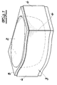
- the basic structure of the sanitary device shown in the figures includes a sanitary tub 2 arranged on feet 1 and a tub cladding 3 designed as a load-bearing component.
- the tub cladding 3 is constructed from panels 4, 4 'which consist of a hard integral polyurethane foam. At least the panels 4 visible in the room have a decorative coating.
- the panels 4, 4 ' are designed as molded parts and have a density of 200 to 800 kg / m 3 , a range up to 600 kg / m 3 being preferred.
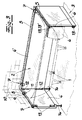
- the molded parts have a cellular structure that can absorb structure-borne noise. Between the tub 2 and the tub cladding 3 there remains a free installation space which, as can be seen in FIG. 3, can be used for installations.
- the abutting edges of the panels can be designed as mitred surfaces, resulting in a butt joint 6, as shown in FIG. 1.
- the decorative coating of the panels preferably consists of a plastic film. However, other coatings should not be excluded.
- the tub 2 can move upward out of the tub cladding 3 be lifted out, but within the tub cladding 3 do not slip.
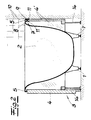
- the upper leg 8, 9 have. 2 shows that a leg 8 encloses an angled edge of the tub 3 and that a leg 9 arranged parallel thereto as a spacer in a gap between the tub edge 5 and the adjacent wall 10 z.
- the holders 7 are on the wall 10 screwable. Your wall-side contact surface can with Be designed for sound decoupling elements.
- the underside is the holder 7 with fastening legs 11 provided, which surround the top edge of the panel in a U-shape.
- the panels 4, 4 ' are by fittings 12 on the inside connected to each other in a frame.
- the fittings 12 can as hinges, angles or as in the exemplary embodiment as Connector be executed.
- the front panel, that is easily accessible in the room is to assembly and Removable for inspection purposes. It is made by fittings fitting parts 13, 13 'which can be locked together releasably the adjacent panels of the tub cladding connected (Fig. 3).
- a wall assigned panels 4 ' one in the exemplary embodiment Long side and an end face, with a lower height are designed as the panels visible in the room 4.
- the wall-side panels 4 ' are supported on feet 14 which form a mounting space.
- a Sealing lip 15 adjacent to the tub edge (FIG. 4).
- the upper edge of the in Panels 4 visible in space with one in front of the tub rim arranged cover strip 16 may be formed, which a Joint 17 between the tub edge 5 and the panels 4 optically covered (Fig. 5).
- the tub edge 5 of a sanitary tub often has rounded Corners on. With large radii of curvature, the Corner areas of the bath paneling gusset between the panels 4, 4 'and the Tub edge 5 result. These must prevent moisture from entering be sealed.
- 6 is a corner filler 18 shown, the one at the rounded corners of the Has tub edge adapted contact surface 19 and to the Tub edge 5 can be glued.
- the corner fillers 18 cover the resulting gusset between the angled interconnected panels 4, 4 'and the tub rim 5 from and are in terms of their surface design especially in color on the surface of the sanitary tub 2 customized.
Landscapes
- Public Health (AREA)
- Health & Medical Sciences (AREA)
- Epidemiology (AREA)
- General Health & Medical Sciences (AREA)
- Residential Or Office Buildings (AREA)
- Bathtub Accessories (AREA)
- Finishing Walls (AREA)
- Infusion, Injection, And Reservoir Apparatuses (AREA)
- Percussion Or Vibration Massage (AREA)
- Bidet-Like Cleaning Device And Other Flush Toilet Accessories (AREA)
- Devices For Medical Bathing And Washing (AREA)
- Beans For Foods Or Fodder (AREA)
- Confectionery (AREA)
- Laminated Bodies (AREA)
- Bathtubs, Showers, And Their Attachments (AREA)
- Polarising Elements (AREA)
Abstract
Description
- Fig. 1
- die perspektivische Darstellung einer erfindungsgemäßen Sanitäreinrichtung mit Wanne und Wannenverkleidung,
- Fig. 2
- einen Schnitt durch den in Fig. 1 dargestellten Gegenstand,
- Fig. 3
- eine weitere Ausgestaltung der erfindungsgemäßen Sanitäreinrichtung in perspektivischer Darstellung, bei teilweise abgenommener Wannenverkleidung,
- Fig. 4 und 5
- weitere Ausgestaltungen der erfindungsgemäßen Sanitäreinrichtung, ausschnittsweise, und
- Fig. 6
- ein Eckenfüllstück zum Anschluß an die erfindungsgemäße Sanitäreinrichtung.
Claims (13)
- Sanitäreinrichtung mit einer auf Füßen (1) angeordneten Wanne (2) und einer Wannenverkleidung (3),
wobei die Wannenverkleidung (3) als tragendes Bauteil aus Paneelen (4, 4') aufgebaut ist und wobei zumindest die in einem Raum sichtbaren Paneele (4) aus einem harten Polyurethan-Integralschaumstoff bestehen und eine Dekorbeschichtung aufweisen. - Sanitäreinrichtung nach Anspruch 1, wobei die Integralschaumstoffkörper eine Dichte von 200 bis 600 kg/m3 aufweisen.
- Sanitäreinrichtung nach Anspruch 1 oder 2, wobei die Dekorbeschichtung der Paneele (4) aus einer Kunststoffolie bestehen.
- Sanitäreinrichtung nach einem der Ansprüche 1 bis 3, wobei zur Lagefixierung der Wanne (2) auf die Oberkante mindestens eines wandseitig angeordneten Paneels (4') Halter (7) aufgesteckt sind, die oberseitige Schenkel (8, 9) aufweisen, wobei ein Schenkel (8) der Halter (7) einen abgewinkelten Rand (5) der Wanne hinterfaßt und ein parallel dazu angeordneter Schenkel (9) sich als Abstandshalter in einen Spalt zwischen dem Wannenrand (5) und einer benachbarten Wand (10) erstreckt.
- Sanitäreinrichtung nach Anspruch 4, wobei die Halter (7) Befestigungsschenkel (11) aufweisen, welche die Paneeloberkante U-förmig einfassen.
- Sanitäreinrichtung nach Anspruch 4 oder 5, wobei die wandseitige Anlagefläche der Halter (7) mit Elementen zur Schallentkopplung ausgebildet ist.
- Sanitäreinrichtung nach einem der Ansprüche 1 bis 6, wobei die Paneele (4, 4') durch innenseitige Beschläge (12) rahmenförmig verbunden sind.
- Sanitäreinrichtung nach einem der Ansprüche 1 bis 7, wobei zumindest ein im Raum zugängliches Paneel (4) durch Beschläge (12) aus miteinander verrastbaren Beschlagteilen (13, 13') lösbar an die benachbarten Paneele (4, 4') der Wannenverkleidung angeschlossen ist.
- Sanitäreinrichtung nach einem der Ansprüche 1 bis 8, wobei die Stoßkanten der Paneele (4, 4') als Gehrungsflächen ausgebildet sind.
- Sanitäreinrichtung nach einem der Ansprüche 1 bis 9, wobei ein wandseitiges Paneel (4') mit einer geringeren Höhe ausgebildet ist als ein im Raum sichtbares frontseitiges Paneel (4) und wobei das wandseitige Paneel (4') auf Füßen (14), die einen Montagefreiraum bilden, abgestützt ist.
- Sanitäreinrichtung nach einem der Ansprüche 1 bis 10, wobei an der Oberkante der Wannenverkleidung (3) eine am Wannenrand (5) anliegende Dichtlippe (15) angeordnet ist.
- Sanitäreinrichtung nach einem der Ansprüche 1 bis 11, wobei die Oberkante der Paneele (4) mit einer vor dem Wannenrand angeordneten Blendleiste ausgebildet ist.
- Sanitäreinrichtung nach einem der Ansprüche 1 bis 12, wobei an den Wannenrand (5) Eckenfüllstücke (18) angeschlossen sind, die eine an gerundete Ecken des Wannenrandes (5) angepaßte Kontaktfläche (19) aufweisen und in den Eckbereichen der Wannenverkleidung (3) Zwickel zwischen dem Wannenrand (5) und den winkelig miteinander verbundenen Paneelen (4, 4') überdecken.
Priority Applications (8)
| Application Number | Priority Date | Filing Date | Title |
|---|---|---|---|
| ES99121126T ES2167982T3 (es) | 1999-10-22 | 1999-10-22 | Instalacion sanitaria. |
| PT99121126T PT1093749E (pt) | 1999-10-22 | 1999-10-22 | Dispositivo sanitario |
| DE59900647T DE59900647D1 (de) | 1999-10-22 | 1999-10-22 | Sanitäreinrichtung |
| EP99121126A EP1093749B1 (de) | 1999-10-22 | 1999-10-22 | Sanitäreinrichtung |
| AT99121126T ATE211370T1 (de) | 1999-10-22 | 1999-10-22 | Sanitäreinrichtung |
| PL00343234A PL343234A1 (en) | 1999-10-22 | 2000-10-17 | Sanitary appliance |
| US09/691,708 US6363546B1 (en) | 1999-10-22 | 2000-10-18 | Sanitary device |
| HU0004119A HU222533B1 (hu) | 1999-10-22 | 2000-10-20 | Szaniterberendezés |
Applications Claiming Priority (1)
| Application Number | Priority Date | Filing Date | Title |
|---|---|---|---|
| EP99121126A EP1093749B1 (de) | 1999-10-22 | 1999-10-22 | Sanitäreinrichtung |
Publications (2)
| Publication Number | Publication Date |
|---|---|
| EP1093749A1 true EP1093749A1 (de) | 2001-04-25 |
| EP1093749B1 EP1093749B1 (de) | 2002-01-02 |
Family
ID=8239265
Family Applications (1)
| Application Number | Title | Priority Date | Filing Date |
|---|---|---|---|
| EP99121126A Expired - Lifetime EP1093749B1 (de) | 1999-10-22 | 1999-10-22 | Sanitäreinrichtung |
Country Status (8)
| Country | Link |
|---|---|
| US (1) | US6363546B1 (de) |
| EP (1) | EP1093749B1 (de) |
| AT (1) | ATE211370T1 (de) |
| DE (1) | DE59900647D1 (de) |
| ES (1) | ES2167982T3 (de) |
| HU (1) | HU222533B1 (de) |
| PL (1) | PL343234A1 (de) |
| PT (1) | PT1093749E (de) |
Cited By (3)
| Publication number | Priority date | Publication date | Assignee | Title |
|---|---|---|---|---|
| CH703416A1 (de) * | 2010-07-09 | 2012-01-13 | Urs Gassmann | Eckausgleichs-Profil. |
| AT13176U1 (de) * | 2008-05-19 | 2013-07-15 | Alpha Bad Gmbh | Klappbare verkleidung für badewannen |
| RU2664269C1 (ru) * | 2017-03-15 | 2018-08-15 | Общество с ограниченной ответственностью "ВАННБОК" | Экран для ванн |
Families Citing this family (4)
| Publication number | Priority date | Publication date | Assignee | Title |
|---|---|---|---|---|
| US7278175B2 (en) * | 2003-11-11 | 2007-10-09 | Lasco Bathware, Inc. | Tub skirt panel system |
| CA2662300A1 (en) * | 2008-04-10 | 2009-10-10 | Maax Bath Inc. | Magnetized apron assembly |
| US20100301175A1 (en) * | 2009-05-31 | 2010-12-02 | Bennett Grayson | Sink brace |
| JP2023176132A (ja) * | 2022-05-31 | 2023-12-13 | パナソニックIpマネジメント株式会社 | 浴槽 |
Citations (4)
| Publication number | Priority date | Publication date | Assignee | Title |
|---|---|---|---|---|
| DE3616421A1 (de) * | 1986-05-15 | 1987-11-26 | Kaldewei Franz Gmbh & Co | Wannentraeger |
| DE19649120A1 (de) * | 1996-11-27 | 1998-05-28 | Villeroy & Boch | Bausatz für die Errichtung von Badewannenverkleidungen |
| DE29905123U1 (de) * | 1999-03-22 | 1999-07-22 | Franz Kaldewei GmbH & Co, 59229 Ahlen | Plattenförmiges Element |
| DE19801043A1 (de) | 1998-01-14 | 1999-07-22 | Kaldewei Franz Gmbh & Co | Verkleidungssystem für eine Wanne, vorzugsweise Badewanne |
Family Cites Families (15)
| Publication number | Priority date | Publication date | Assignee | Title |
|---|---|---|---|---|
| US1882514A (en) * | 1931-12-18 | 1932-10-11 | Andrew Main | Bathtub support |
| US2117233A (en) * | 1937-05-07 | 1938-05-10 | Rufus B Clark | Bathtub support |
| US2305846A (en) * | 1940-08-15 | 1942-12-22 | Briggs Mfg Co | Bathtub |
| US2697231A (en) * | 1953-06-25 | 1954-12-21 | Carl A Strand | Lightweight bathtub construction |
| US2982972A (en) * | 1958-11-06 | 1961-05-09 | Allianceware Inc | Bathtub |
| GB1140809A (en) | 1966-12-01 | 1969-01-22 | Arenco Ab | A device for cutting cigar wrappers or binders |
| CH519327A (de) * | 1969-08-28 | 1972-02-29 | Correcta Werke Ges Mit Beschra | Verfahren für den Einbau einer Badewanne in ein Bauwerk und hierfür vorgesehener Badewannenträger |
| US4290154A (en) * | 1979-11-13 | 1981-09-22 | Benjamin Manufacturing Company, Inc. | Bathtub structure |
| DE3329649A1 (de) * | 1983-08-17 | 1985-02-28 | Correcta GmbH, 3590 Bad Wildungen | Wannenschuerze |
| GB2224202B (en) * | 1986-02-19 | 1990-10-17 | Carron Plastics | Method of mounting plastics vessels |
| GB8705115D0 (en) * | 1987-03-05 | 1987-04-08 | Ideal Standard | Bath/shower-tray installation |
| US5428849A (en) * | 1994-03-03 | 1995-07-04 | Watkins Manufacturing Corporation | Portable spa with integral bottom pan, interchangeable side skirt, and interlocking cover |
| US5477568A (en) * | 1995-01-03 | 1995-12-26 | Wang; Sung-Shun | Bathtub assembly |
| DE19627836A1 (de) * | 1996-07-10 | 1998-01-15 | Missel Gmbh & Co E | Vorrichtung zur körperschallentkoppelten Fixierung der Ränder von Bade- und Duschwannen |
| US5960489A (en) * | 1997-07-29 | 1999-10-05 | E. Missel Gmbh | Support system for bath or shower tubs |
-
1999
- 1999-10-22 PT PT99121126T patent/PT1093749E/pt unknown
- 1999-10-22 AT AT99121126T patent/ATE211370T1/de not_active IP Right Cessation
- 1999-10-22 ES ES99121126T patent/ES2167982T3/es not_active Expired - Lifetime
- 1999-10-22 EP EP99121126A patent/EP1093749B1/de not_active Expired - Lifetime
- 1999-10-22 DE DE59900647T patent/DE59900647D1/de not_active Expired - Fee Related
-
2000
- 2000-10-17 PL PL00343234A patent/PL343234A1/xx not_active IP Right Cessation
- 2000-10-18 US US09/691,708 patent/US6363546B1/en not_active Expired - Fee Related
- 2000-10-20 HU HU0004119A patent/HU222533B1/hu not_active IP Right Cessation
Patent Citations (4)
| Publication number | Priority date | Publication date | Assignee | Title |
|---|---|---|---|---|
| DE3616421A1 (de) * | 1986-05-15 | 1987-11-26 | Kaldewei Franz Gmbh & Co | Wannentraeger |
| DE19649120A1 (de) * | 1996-11-27 | 1998-05-28 | Villeroy & Boch | Bausatz für die Errichtung von Badewannenverkleidungen |
| DE19801043A1 (de) | 1998-01-14 | 1999-07-22 | Kaldewei Franz Gmbh & Co | Verkleidungssystem für eine Wanne, vorzugsweise Badewanne |
| DE29905123U1 (de) * | 1999-03-22 | 1999-07-22 | Franz Kaldewei GmbH & Co, 59229 Ahlen | Plattenförmiges Element |
Cited By (3)
| Publication number | Priority date | Publication date | Assignee | Title |
|---|---|---|---|---|
| AT13176U1 (de) * | 2008-05-19 | 2013-07-15 | Alpha Bad Gmbh | Klappbare verkleidung für badewannen |
| CH703416A1 (de) * | 2010-07-09 | 2012-01-13 | Urs Gassmann | Eckausgleichs-Profil. |
| RU2664269C1 (ru) * | 2017-03-15 | 2018-08-15 | Общество с ограниченной ответственностью "ВАННБОК" | Экран для ванн |
Also Published As
| Publication number | Publication date |
|---|---|
| HU0004119D0 (en) | 2000-12-28 |
| US6363546B1 (en) | 2002-04-02 |
| HU222533B1 (hu) | 2003-08-28 |
| PT1093749E (pt) | 2002-06-28 |
| PL343234A1 (en) | 2001-04-23 |
| ATE211370T1 (de) | 2002-01-15 |
| ES2167982T3 (es) | 2002-05-16 |
| DE59900647D1 (de) | 2002-02-21 |
| EP1093749B1 (de) | 2002-01-02 |
| HUP0004119A2 (hu) | 2001-09-28 |
Similar Documents
| Publication | Publication Date | Title |
|---|---|---|
| EP0870459B1 (de) | Trägersystem für Bade-, Dusch- oder Whirlwannen | |
| EP1093749B1 (de) | Sanitäreinrichtung | |
| DE102012111579A1 (de) | Sanitärwanne und Wanneninstallation | |
| DE3602962A1 (de) | Fertigbauelement fuer eine aus teilstuecken zusammensetzbare rinne | |
| DE4126383C2 (de) | Verfahren und Montageelement zur Montage von Bade- und Duschwannen | |
| EP0281957A1 (de) | Segmentförmige Wanne | |
| DE8507269U1 (de) | Vorrichtung zum Abstützen und Verkleiden von Sanitärbecken, insbesondere von Badewannen und Brausetassen | |
| DE102012105555A1 (de) | Aufnahmeeinheit zur Aufnahme einer Wiegeeinheit und Anordnung zur Ermittlung einer Masse | |
| DE202018105009U1 (de) | Sanitäreinrichtung | |
| EP1174066B1 (de) | Fixiervorrichtung | |
| DE69108872T2 (de) | Verbindungseinrichtung zwischen dem Rand eines Doppelbodens und der benachbarten Wand. | |
| EP0723757A1 (de) | Trägersystem für Bade- oder Duschwannen | |
| DE10311845B3 (de) | Rohbaumontagesystem mit einem Montagerahmen und einer Bad-oder Duschwanne | |
| EP1511145A2 (de) | Im Bodenaufbau verlegbarer Kanal | |
| DE9410545U1 (de) | Trageinrichtung für eine Bade- oder Duschwanne | |
| EP1445554B1 (de) | Heizgerät | |
| DE202012102345U1 (de) | Aufnahmeeinheit zur Aufnahme einer Wiegeeinheit und Anordnung zur Ermittlung einer Masse | |
| DE20303281U1 (de) | Wannenverkleidung für eine Sanitärbadewanne | |
| EP0865751A2 (de) | Wannenverkleidung | |
| DE29905138U1 (de) | Wannen-Verkleidung | |
| DE29505183U1 (de) | Verteilerkasten | |
| DE102004011827A1 (de) | Untergestell für Sanitärwannen | |
| DE8703583U1 (de) | Segmentförmige Wanne | |
| DE29602829U1 (de) | Dusch- und Badeanordnung | |
| DE4244562A1 (de) | Trägersystem für eine Bade- oder Brausewanne |
Legal Events
| Date | Code | Title | Description |
|---|---|---|---|
| PUAI | Public reference made under article 153(3) epc to a published international application that has entered the european phase |
Free format text: ORIGINAL CODE: 0009012 |
|
| 17P | Request for examination filed |
Effective date: 20000429 |
|
| AK | Designated contracting states |
Kind code of ref document: A1 Designated state(s): AT BE CH CY DE DK ES FI FR GB GR IE IT LI LU MC NL PT SE |
|
| AX | Request for extension of the european patent |
Free format text: AL;LT;LV;MK;RO;SI |
|
| GRAG | Despatch of communication of intention to grant |
Free format text: ORIGINAL CODE: EPIDOS AGRA |
|
| GRAG | Despatch of communication of intention to grant |
Free format text: ORIGINAL CODE: EPIDOS AGRA |
|
| GRAH | Despatch of communication of intention to grant a patent |
Free format text: ORIGINAL CODE: EPIDOS IGRA |
|
| GRAH | Despatch of communication of intention to grant a patent |
Free format text: ORIGINAL CODE: EPIDOS IGRA |
|
| RAP1 | Party data changed (applicant data changed or rights of an application transferred) |
Owner name: FRANZ KALDEWEI GMBH & CO.KG |
|
| GRAA | (expected) grant |
Free format text: ORIGINAL CODE: 0009210 |
|
| REG | Reference to a national code |
Ref country code: GB Ref legal event code: IF02 |
|
| AK | Designated contracting states |
Kind code of ref document: B1 Designated state(s): AT BE CH CY DE DK ES FI FR GB GR IE IT LI LU MC NL PT SE |
|
| PG25 | Lapsed in a contracting state [announced via postgrant information from national office to epo] |
Ref country code: IE Free format text: LAPSE BECAUSE OF FAILURE TO SUBMIT A TRANSLATION OF THE DESCRIPTION OR TO PAY THE FEE WITHIN THE PRESCRIBED TIME-LIMIT Effective date: 20020102 Ref country code: GR Free format text: LAPSE BECAUSE OF FAILURE TO SUBMIT A TRANSLATION OF THE DESCRIPTION OR TO PAY THE FEE WITHIN THE PRESCRIBED TIME-LIMIT Effective date: 20020102 Ref country code: FI Free format text: LAPSE BECAUSE OF FAILURE TO SUBMIT A TRANSLATION OF THE DESCRIPTION OR TO PAY THE FEE WITHIN THE PRESCRIBED TIME-LIMIT Effective date: 20020102 |
|
| REF | Corresponds to: |
Ref document number: 211370 Country of ref document: AT Date of ref document: 20020115 Kind code of ref document: T |
|
| REG | Reference to a national code |
Ref country code: CH Ref legal event code: NV Representative=s name: KELLER & PARTNER PATENTANWAELTE AG Ref country code: CH Ref legal event code: EP |
|
| AKX | Designation fees paid |
Free format text: AT BE CH CY DE DK ES FI FR GB GR IE IT LI LU MC NL PT SE |
|
| REG | Reference to a national code |
Ref country code: IE Ref legal event code: FG4D Free format text: GERMAN |
|
| REF | Corresponds to: |
Ref document number: 59900647 Country of ref document: DE Date of ref document: 20020221 |
|
| PG25 | Lapsed in a contracting state [announced via postgrant information from national office to epo] |
Ref country code: SE Free format text: LAPSE BECAUSE OF FAILURE TO SUBMIT A TRANSLATION OF THE DESCRIPTION OR TO PAY THE FEE WITHIN THE PRESCRIBED TIME-LIMIT Effective date: 20020402 Ref country code: DK Free format text: LAPSE BECAUSE OF FAILURE TO SUBMIT A TRANSLATION OF THE DESCRIPTION OR TO PAY THE FEE WITHIN THE PRESCRIBED TIME-LIMIT Effective date: 20020402 |
|
| GBT | Gb: translation of ep patent filed (gb section 77(6)(a)/1977) |
Effective date: 20020404 |
|
| REG | Reference to a national code |
Ref country code: ES Ref legal event code: FG2A Ref document number: 2167982 Country of ref document: ES Kind code of ref document: T3 |
|
| ET | Fr: translation filed | ||
| REG | Reference to a national code |
Ref country code: PT Ref legal event code: SC4A Free format text: AVAILABILITY OF NATIONAL TRANSLATION Effective date: 20020313 |
|
| REG | Reference to a national code |
Ref country code: IE Ref legal event code: FD4D |
|
| PGFP | Annual fee paid to national office [announced via postgrant information from national office to epo] |
Ref country code: AT Payment date: 20021008 Year of fee payment: 4 |
|
| PGFP | Annual fee paid to national office [announced via postgrant information from national office to epo] |
Ref country code: FR Payment date: 20021010 Year of fee payment: 4 |
|
| PGFP | Annual fee paid to national office [announced via postgrant information from national office to epo] |
Ref country code: PT Payment date: 20021018 Year of fee payment: 4 |
|
| PGFP | Annual fee paid to national office [announced via postgrant information from national office to epo] |
Ref country code: LU Payment date: 20021024 Year of fee payment: 4 |
|
| PG25 | Lapsed in a contracting state [announced via postgrant information from national office to epo] |
Ref country code: CY Free format text: LAPSE BECAUSE OF FAILURE TO SUBMIT A TRANSLATION OF THE DESCRIPTION OR TO PAY THE FEE WITHIN THE PRESCRIBED TIME-LIMIT Effective date: 20021031 |
|
| PGFP | Annual fee paid to national office [announced via postgrant information from national office to epo] |
Ref country code: ES Payment date: 20021108 Year of fee payment: 4 |
|
| PLBE | No opposition filed within time limit |
Free format text: ORIGINAL CODE: 0009261 |
|
| STAA | Information on the status of an ep patent application or granted ep patent |
Free format text: STATUS: NO OPPOSITION FILED WITHIN TIME LIMIT |
|
| PGFP | Annual fee paid to national office [announced via postgrant information from national office to epo] |
Ref country code: BE Payment date: 20021122 Year of fee payment: 4 |
|
| 26N | No opposition filed | ||
| PG25 | Lapsed in a contracting state [announced via postgrant information from national office to epo] |
Ref country code: MC Free format text: LAPSE BECAUSE OF NON-PAYMENT OF DUE FEES Effective date: 20030501 |
|
| PG25 | Lapsed in a contracting state [announced via postgrant information from national office to epo] |
Ref country code: LU Free format text: LAPSE BECAUSE OF NON-PAYMENT OF DUE FEES Effective date: 20031022 Ref country code: GB Free format text: LAPSE BECAUSE OF NON-PAYMENT OF DUE FEES Effective date: 20031022 Ref country code: AT Free format text: LAPSE BECAUSE OF NON-PAYMENT OF DUE FEES Effective date: 20031022 |
|
| PG25 | Lapsed in a contracting state [announced via postgrant information from national office to epo] |
Ref country code: ES Free format text: LAPSE BECAUSE OF NON-PAYMENT OF DUE FEES Effective date: 20031023 |
|
| PG25 | Lapsed in a contracting state [announced via postgrant information from national office to epo] |
Ref country code: LI Free format text: LAPSE BECAUSE OF NON-PAYMENT OF DUE FEES Effective date: 20031031 Ref country code: CH Free format text: LAPSE BECAUSE OF NON-PAYMENT OF DUE FEES Effective date: 20031031 Ref country code: BE Free format text: LAPSE BECAUSE OF NON-PAYMENT OF DUE FEES Effective date: 20031031 |
|
| BERE | Be: lapsed |
Owner name: FRANZ *KALDEWEI G.M.B.H. & CO. K.G. Effective date: 20031031 |
|
| PG25 | Lapsed in a contracting state [announced via postgrant information from national office to epo] |
Ref country code: PT Free format text: LAPSE BECAUSE OF NON-PAYMENT OF DUE FEES Effective date: 20040430 |
|
| PG25 | Lapsed in a contracting state [announced via postgrant information from national office to epo] |
Ref country code: NL Free format text: LAPSE BECAUSE OF NON-PAYMENT OF DUE FEES Effective date: 20040501 |
|
| GBPC | Gb: european patent ceased through non-payment of renewal fee |
Effective date: 20031022 |
|
| REG | Reference to a national code |
Ref country code: CH Ref legal event code: PL |
|
| PG25 | Lapsed in a contracting state [announced via postgrant information from national office to epo] |
Ref country code: FR Free format text: LAPSE BECAUSE OF NON-PAYMENT OF DUE FEES Effective date: 20040630 |
|
| NLV4 | Nl: lapsed or anulled due to non-payment of the annual fee |
Effective date: 20040501 |
|
| REG | Reference to a national code |
Ref country code: FR Ref legal event code: ST Ref country code: PT Ref legal event code: MM4A Free format text: LAPSE DUE TO NON-PAYMENT OF FEES Effective date: 20040430 |
|
| REG | Reference to a national code |
Ref country code: ES Ref legal event code: FD2A Effective date: 20031023 |
|
| PGFP | Annual fee paid to national office [announced via postgrant information from national office to epo] |
Ref country code: DE Payment date: 20050722 Year of fee payment: 7 |
|
| PG25 | Lapsed in a contracting state [announced via postgrant information from national office to epo] |
Ref country code: IT Free format text: LAPSE BECAUSE OF NON-PAYMENT OF DUE FEES Effective date: 20051022 |
|
| PG25 | Lapsed in a contracting state [announced via postgrant information from national office to epo] |
Ref country code: DE Free format text: LAPSE BECAUSE OF NON-PAYMENT OF DUE FEES Effective date: 20070501 |