EP0723757A1 - Trägersystem für Bade- oder Duschwannen - Google Patents
Trägersystem für Bade- oder Duschwannen Download PDFInfo
- Publication number
- EP0723757A1 EP0723757A1 EP95111633A EP95111633A EP0723757A1 EP 0723757 A1 EP0723757 A1 EP 0723757A1 EP 95111633 A EP95111633 A EP 95111633A EP 95111633 A EP95111633 A EP 95111633A EP 0723757 A1 EP0723757 A1 EP 0723757A1
- Authority
- EP
- European Patent Office
- Prior art keywords
- wall
- tub
- sound
- support
- layer
- Prior art date
- Legal status (The legal status is an assumption and is not a legal conclusion. Google has not performed a legal analysis and makes no representation as to the accuracy of the status listed.)
- Granted
Links
Images









Classifications
-
- A—HUMAN NECESSITIES
- A47—FURNITURE; DOMESTIC ARTICLES OR APPLIANCES; COFFEE MILLS; SPICE MILLS; SUCTION CLEANERS IN GENERAL
- A47K—SANITARY EQUIPMENT; ACCESSORIES THEREFOR, e.g. TOILET ACCESSORIES
- A47K3/00—Baths; Showers; Appurtenances therefor
- A47K3/008—Sealing between wall and bathtub or shower tray
Definitions
- the invention relates to a support system for bathtubs or shower trays, which are provided with a peripheral rim in particular, with at least one mounting rail which can be fastened on the wall and support members which can be provided between the tub and the floor.
- This object is achieved according to the invention essentially in that the surfaces of the wall and / or the mounting rail facing the tub edge are covered at least in regions with a sound decoupling layer, that the support members have at least one sound-decoupling insulating element, and that a sound-decoupling profile element is provided, which between the tub rim and the area facing it, a support wall that can be erected below the tub rim can be positioned.
- the principle according to the invention is that sound decoupling is provided consistently at all those points at which the trough is connected to the structure or is supported on an element connected to the structure. Since the tubs are supported on the one hand via their tub edge on support rails connected to the structure or support walls erected in front of the tub and on the other hand because of the tub floor on floating screeds or raw ceilings, sound-decoupling materials are provided according to the invention at these locations between the tub and the element supporting it .
- This consistent sound decoupling means that, when using a carrier system according to the invention, it is possible, for example, to dispense with acoustically decoupling support walls or load-bearing drywall walls or the floor area located under the tub from the rest of the structure. Since the sound decoupling of retaining walls, load-bearing drywall or floor areas represents a considerable outlay in comparison to the attachment of the carrier system according to the invention, the invention creates a system which is very economical and easy to handle compared to the prior art, with which, in addition, a system compared to the prior art Technology improved sound decoupling of the tub from the building is achievable.
- the sound level of bathtubs and shower trays which are held by a carrier system according to the invention is less than 30 dB (A) for a diagonal measurement, while for systems according to the prior art sound levels above 40 dB (A) are measured.
- the carrier system according to the invention can be used for all commercially available bathtubs and shower trays of any shape, these shower trays being made of steel, cast iron or plastic.
- these shower trays being made of steel, cast iron or plastic.
- straight support rails or profile elements can be provided, while when using differently shaped, for example round, semicircular or oval tubs of this shape, correspondingly adapted support rails or profile elements must be used.
- the simple construction of the carrier system according to the invention has proven to be particularly advantageous, on the basis of which the assembly can be learned and carried out easily, the assembly effort being limited to a minimum.
- the simple structure ensures that the parts used in the framework of the carrier system according to the invention are so robust that they can easily withstand construction site operation without losing their acoustic or sound-decoupling properties.
- the individual parts of the carrier system according to the invention can be made available in different sizes or can be assembled into different sizes in a modular manner, little or no waste is produced when the carrier system according to the invention is assembled, which is an advantage from an environmental point of view.
- the support system according to the invention can be used to attach a tub at any installation height customary in sanitary engineering practice, since the mounting rails can each be attached to a wall at any height, and the profile elements are provided on supporting walls of any height can and the floor-side support members either adjustable or can be provided at different heights, so that different distances between the screed or raw ceiling and tub floor can be realized.
- the fitter can easily adjust to various installation situations, that is to say the support system can be attached both before and after tiling a bath, both thin and thick bed tiling being able to be used.
- This flexible application of the support system according to the invention is explained in more detail in the context of the figure description, reference being made in particular to the fact that tubs can be attached without problems with one, two or three-sided wall connection.
- the measures described ensure, on the one hand, that there is no direct contact between the mounting rail and the tub rim in the context of the wall connection of the tub, on the other hand, a wall-side sound decoupling element can also be provided, which is between the wall on which the Carrier rail is attached, and the area of the tub edge facing it can be positioned.
- the tub supported on the support rail covered with the sound decoupling layer can in this case during installation not slide so close to the wall that there is direct contact between the tub and the wall, since the mentioned additional sound decoupling element is provided between the tub and the wall.
- the additional sound decoupling element can also serve to ensure a uniform distance between the tub and the wall or between the tub and a tiling to be applied subsequently.
- sound-decoupling materials that can be used in the context of the invention, in particular the sound decoupling layer of the mounting rail, the insulating element of the support members, the profile element of the support wall and the wall-side sound decoupling element can be made of soft springy material, soft plastic, polystyrene, cork, elastomeric substances, rubber , Natural rubber, coconut, soft foam, in particular PE foam, rigid foam or the like, or consist of combinations of these materials.
- the mounting rail, the profile element which can be positioned between the tub edge and the support wall and / or the wall-side sound decoupling element are designed as individual parts which can be attached to one another in the longitudinal direction and in particular have a length of 60, 90 or 120 cm.
- the carrier system according to the invention can be adapted to different tub sizes without difficulty and also be sold in small, handy packaging units.
- all parts of the carrier system according to the invention are designed to be moisture-resistant.
- FIG. 1 a shows the top view of a bathtub 1 which is supported on two sides on a wall 3 and on at least one further side on a support wall 4, 12 with a carrier system according to the invention.
- the tub floor 6 is supported against the screed by a support member 7a.
- two further support members 7b are provided, which also support the tub rim in two of its corner areas with respect to the screed.
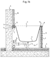
- FIG. 1b shows a sectional view along the section line AA according to FIG. 1a.
- the sectional view of the bathtub 1 can be seen, which is supported with a carrier system according to the invention on the one hand via a mounting rail 2 on the wall 3 and on the other hand on the support wall 4 opposite the mounting rail 2.
- three support members 7a, 7b are provided between the screed 5 and the tub edge and / or the tub floor 6, only two of which are visible in FIG. 1.
- An embodiment is also conceivable in which only two or even more than three support members 7a, 7b are provided.
- the tub 1 has a circumferential, outwardly bent tub rim 8, by means of which the tub 1 is supported on the support wall 4, on the support rail 2 and on the support members 7b.
- the tub rim 8 can also be supported only on one or more support members, the structure of which corresponds to the support members 7b shown in FIG. 1 can, however, the length of the screed 5 - tub edge 8 must be adjusted in length.
- the mounting rail 2 has a Z-shaped profile and is attached to the wall 3, for example by means of a screw connection.
- the mounting rail 2 attached to the wall 3 forms, together with the wall 3, a U-shaped, upwardly open receptacle for a sound decoupling layer 9, the profile of which is adapted to the mounting rail and on which the tub edge 8 is supported.
- the wall 3 is provided with a tiling 10, which ends above the tub edge 8.
- a sound-decoupling element 11 with an L-shaped cross section is provided, which brings about an additional sound decoupling of trough 1 with respect to wall 3 or tiling 10 and also a constant and uniform distance between Tub edge 8 and tiling 10 or between tub edge 8 and wall 3 ensures.
- the support wall 4 which is also provided with a tiling 12, is covered in its upper region with a sound-decoupling profile element 13, which is adapted in shape to the tiled support wall 2 and ensures that direct contact between the tub edge 8 or tub 1 and the supporting wall 4 or Tiling 12 is avoided.
- the support members 7a, 7b have at least one sound-decoupling insulating element, which ensures that no structure-borne sound bridges can arise between the tub floor 6 and the screed 5 or between the tub edge 8 and the screed 5.
- a possible embodiment of a support member 7a, 7b is shown for example in FIGS. 13a and 13b.
- the support members are arranged on the side of the tub or the tub bottom 6 facing away from the mounting rail 2. In this way, sufficient space for the provision of pipelines 14 is created on the side of the trough base 6 facing the mounting rail 2.
- the support members are each offset approximately at the same distance from the wall 3 in the longitudinal direction of the tub.
- FIG. 1c essentially corresponds to FIG. 1b, only the support members 7b arranged in the corner regions of the tub 1 can be seen completely here. These support members 7b are variable in length and thus adaptable to the distance between the tub edge 8 and screed 5.
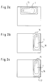
- FIG. 2a to 2c show different situations that may exist when installing a bathtub in a bathroom.
- the tub 1 is only with one of its long sides against a wall 15.
- the tub 1 is held on the wall 15 by means of a mounting rail according to the invention.
- the other three sides of the tub 1 are supported on supporting walls erected below it.
- FIG. 2b shows a two-sided wall connection of the tub 1 to the walls 15 and 16, the two sides of the tub 1 opposite the walls 15 and 16 each being supported by supporting walls.
- 2c shows a three-sided wall connection of the tub 1 to the walls 15, 16 and 17, the tub 1 being supported by a supporting wall only on the side opposite the wall 16.
- the tub In an installation situation according to FIGS. 2b and 2c, the tub must be held on at least one of the walls 15, 16 or 15, 16, 17 by means of a support rail, but it is also possible for the tub 1 to be attached to several of the walls 15, 16 16 or 15, 16, 17 is held by means of a mounting rail.
- the number of mounting rails used in an installation situation according to FIGS. 2b and 2c depends, for example, on the tub material used, with all-round edge support generally being required for plastic tubs, while support is also required for tubs made of steel or cast iron on only one retaining wall and an opposite wall can suffice.
- Fig. 14 If dry planking (Fig. 14) is used instead of walling in, it is necessary to support a tub with its tub edge using at least two support elements on the floor and at the edge. Furthermore, the floor of the tub is to be supported on the floor by at least one support member. Possible embodiments of suitable support members are described in connection with FIGS. 13a and 13b.
- a sound-decoupling wall attachment must be provided, which can be accomplished, for example, with a suitably designed tension anchor (DE 43 24 133.6, EP 94 110 896.1) or a similar device.
- FIG. 3 shows a detailed view of the carrier system according to the invention, in which a tub rim 8 which is bent outwards in a conventional manner is fastened to a wall 3 via a mounting rail 2.
- the mounting rail 2 is designed in accordance with FIG. 1 and in this way creates, together with the wall 3, an upwardly open receptacle for a sound-decoupling layer 18 which is essentially U-shaped in cross section, which in turn has an upwardly open receptacle for the tub edge 8.
- Galvanized steel, aluminum and the like are suitable, for example, for the production of the mounting rail 2, it being preferred to ensure that the material used is moisture-resistant.
- the opening of the sound decoupling layer 18, which is open at the top and is suitable for receiving the tub edge 8, is covered with a load distribution layer 19, which is made in particular from hard plastic, aluminum or the like can.
- the load distribution layer 19 is preferably glued or pressed into the recess of the sound decoupling layer 18. Through the load distribution layer 19, the tub load or the total load of the tub, water and user can be distributed uniformly over the length of the mounting rail 2.
- the load distribution layer 19 is not required if a material is used as the sound decoupling layer 18 which has both good sound decoupling properties and is mechanically resilient without resulting in excessive deformation.
- a material is used as the sound decoupling layer 18 which has both good sound decoupling properties and is mechanically resilient without resulting in excessive deformation.
- the use of a polyurethane elastomer offers itself.
- a sound decoupling element 20 is provided which has an L-shaped cross section, one leg of this sound decoupling element 20 extending horizontally above the tub rim 8 and the other leg vertically between the tub rim 8 and wall 3 .
- the sound decoupling element 20 performs two tasks: On the one hand, the sound decoupling element 20 brings about an effective sound decoupling between the tub edge 8 and the wall 3. The provision of the sound decoupling element 20 makes it impossible for the tub to slip, for example, in such a way that the tub edge 8 comes to rest directly on the wall 3 and in this way a sound bridge arises.
- the sound decoupling element which has a constant cross-section over its entire length, ensures that a uniform distance is maintained between the tub edge 8 and the wall 3 and also a constant distance between a tiling 21 attached to the wall 3 above the tub edge 8 on the tub edge 8 is ensured.
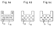
- FIG. 4 shows possible embodiments of the sound decoupling layer 18 according to FIG. 3.
- it can be provided with openings which extend in particular in the direction of its longitudinal axis or also transversely thereto.
- These openings which can also be contained in other sound-decoupling elements of the carrier system according to the invention, preferably have the following cross sections:
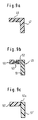
- FIG. 4a shows openings in the form of elongated holes 22
- FIG. 4b shows openings in the form of bores 23
- FIG. 4c shows openings in the form of rectangular openings 24.
- any other shapes of the openings 22, 23, 24 can also be used realize.
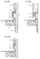
- Fig. 5 shows an embodiment in which a tub with its tub edge 8 is attached to an already tiled wall 25 by means of a mounting rail 2.
- Support rail 2 sound decoupling element 18 'and load distribution layer 19' are designed analogously to FIG. 3, it being apparent from FIG. 5 that other cross-sectional shapes are also possible with regard to the cross section of the sound decoupling layer 18 and the load distribution layer 19 according to FIG. 3.
- the sound decoupling element 20 serves on the one hand to soundproof the tub edge 8 and wall 25 and on the other hand ensures a constant distance between the tub edge 8 and wall 25.
- the cross section of the sound decoupling element 20 in the embodiment according to FIG. 5 can be selected to be rectangular, since the sound decoupling element 20 ′, in contrast to the embodiment according to FIG. 3, in which it has an L-shaped cross section, does not have a constant vertical distance between tiling and tub edge 8 must take care, since the wall 25 according to FIG. 5 is already completely tiled.
- a permanently elastic for example from, is above the sound decoupling element 20 'between the tub edge 8 and the wall 25 Silicone existing joint 26 is provided.
- the joint can also be used to adjust the color, for example.
- a major advantage of the system according to the invention is that the joint 26 no longer has to take on an acoustic, sound-decoupling function in comparison to the prior art, and when the joint 26 is attached no consideration needs to be given to such sound-decoupling properties, since the sound decoupling already takes place through the Provided the sound decoupling layer 18 'and the sound decoupling element 20' is ensured.
- FIG. 6a to 6c show possible cross-sectional shapes of a sound decoupling element which can be provided between the tub edge 8 and the wall 3.
- the sound decoupling element 27 according to FIG. 6a is dimensioned such that it can be used in connection with a thick-bed tiling 28 attached to the wall 3.
- the sound decoupling element 27 specifies the corresponding distance. Likewise, there is a comparatively smaller distance between the tub edge 8 and wall 3 in its lower region in the thick bed tiling according to FIG. 6a.
- the sound decoupling element 27 'according to FIG. 6b essentially corresponds to the sound decoupling element 27 according to FIG. 6a, a recess 29 being provided according to FIG. 6b in the area located above the tub edge 8 and facing the tiles.
- the sound decoupling element 27 ' is also suitable for thick-bed tiling 28.
- FIGS. 6a and 6b shows a sound decoupling element 27 ′′ which is suitable for thin-bed tiling 30.
- the horizontal dimensions of the sound decoupling element 27 ′′ in the area located between the wall 3 and the tiles is correspondingly smaller here in comparison to FIGS. 6a and 6b.
- All sound decoupling elements 27, 27 ', 27' 'according to FIGS. 6a to 6c are provided with a sealing lip 31 which extends horizontally above the tub edge 8 from the wall 3 and is rounded in its end region, which ensures that no splashing and splashing water can penetrate into the area between the tub rim 8 and wall 3.
- the provision of the sealing lip 31, which rests in particular on the upper side of the tub rim 8 under prestress, makes the use of an additional silicone joint superfluous, as a result of which the assembly effort is further reduced.
- the sound decoupling elements 33 to 35 according to FIGS. 7a to 7c are suitable for use with a wall to be retrofitted.
- the upper region of the sound decoupling elements 33 to 35 is designed such that when the sound decoupling element is inserted it essentially has the appearance of a joint which tapers along the wall 3 and along the rim 8 of the tub.
- the sound decoupling elements 33 to 35 seal the gap existing between the tub edge 8 and the wall 3.
- FIG. 7a shows a sound decoupling element 33, which has a tapered sealing lip 37 which rests under prestress on the tub edge 8.
- a corresponding sealing lip 37 ' also has the sound decoupling element 34 according to FIG. 7b, wherein the two legs of the sound decoupling element 34 which run at right angles to one another after installation can run at an acute angle to one another before installation, for example, in order to likewise preload after installation To reach sealing lip 37 opposite the tub rim 8.
- a particularly good sealing effect can be achieved with the described pre-tensioning according to FIGS. 7a and 7b.
- the sound decoupling element 35 according to FIG. 7c has a groove 38 which extends vertically downward from its upper edge and into which a tile 39 can engage.
- the width of the groove 38 is adapted to the thickness of the tile 39, a particularly good seal between the tiled wall and the tub edge 8 can be achieved.
- FIG. 8 shows the wall-side support of a tub edge 40, which is not bent outwards and downwards in a conventional manner, but is designed as a raised tub edge 40.
- the carrier system according to the invention can also be used advantageously in connection with such support edges 40.
- a likewise Z-shaped mounting rail 2 offers the use of a sound-decoupling layer 41 which is essentially L-shaped in cross section and which, with its thinner, vertically upwardly extending leg, defines the distance between the tub rim 40 and the wall 3.
- the sound decoupling layer 41 can be covered with a load distribution layer 42 in accordance with the examples already described, but this is now adapted to the shape of the sound decoupling layer 41 and consequently likewise has an L-shaped cross section.
- a Z-shaped retaining profile 43 is fastened to the wall 3, which overlaps the upwardly bent area of the tub rim 40 from above, forming a gap between the tub rim 40 and the retaining profile 43.
- a sound decoupling element 44 is arranged, which extends vertically in this gap and horizontally towards the wall 3 above the tub edge 40, so that the sound decoupling element 44 has an overall L-shaped cross section.
- Tiles 45 attached to the wall 3 end immediately above the horizontally extending area of the holding profile 43, so that this area of the holding profile 43, which runs at a constant vertical distance from the tub edge 42, ensures a constant distance between the tiles 45 and the tub edge 40.
- a gap which may be present between tiles 45 and holding profile 43 can be sealed by means of a joint 46, which is made in particular of silicone.
- the horizontal dimensions of the holding profile 43 and the sound decoupling element 44 can also be chosen to be correspondingly smaller in accordance with FIG. 8b, so as to create a flush transition on the room side between tiles 45 'and the lower, vertically running region of the holding profile 43'. With this flush transition, there is no need to use a silicone joint.
- FIGS. 8a and 8b are each suitable for use with a thin bed tiling.
- FIG. 8c shows an embodiment which is suitable for use with thick-bed tiling.
- the horizontal dimensions of the holding profile 43 ′′ and the sound decoupling element 44 ′′ are chosen to be correspondingly larger.
- FIG. 9a to 9c show possible embodiments of a sound decoupling element, such as can be used in a device according to FIG. 3, for example.
- the sound decoupling element 47 according to FIG. 9 a can be provided with a predetermined breaking point 48 at which a part of the sound decoupling element can be broken off, and so on to be able to shorten its horizontal area according to the respective requirements. It is also possible to provide a plurality of predetermined breaking points 48 at a distance from one another.
- the sound decoupling element 47 can also be cut off before or after assembly, for example by means of a knife, in accordance with the respective requirements.
- 9b shows a sound decoupling element 49 which has an essentially L-shaped cross section and consists of two parts 50, 51.
- the substantially vertically extending part 51 has a horizontal groove 52 into which a spring 53 attached to the essentially horizontally extending part engages.
- the spring 53 is horizontally displaceable in the groove 52.
- This configuration makes it possible to adjust the horizontal dimensions of the sound decoupling element 49 by moving the two parts 50, 52 relative to one another in accordance with the respective requirements.
- 10a to 10c show further possible embodiments of a sound decoupling layer, with which a mounting rail 2 can be covered.
- the sound decoupling layers according to FIGS. 10a to 10c all have the following layer structure:
- the outermost layer which is in direct contact with the mounting rail or the wall 3, is formed by a film 54, in particular reinforced by a lattice structure.
- a fiber layer 55 On the inside there is a fiber layer 55, on the inside of which a foam layer 56 is in turn arranged.
- the layer composite 54, 55, 56 has an essentially U-shaped cross section, the free inner cross section of which is filled in its lower region with a sound-absorbing cushion layer 57.
- FIG. 10b essentially corresponds to the described embodiment according to FIG. 10a the difference that the inner foam layer 56 'according to FIG. 10b is provided with a groove profile.
- the top of the cushion layer 57, on which the tub edge of the tub, which is not shown in FIG. 10, is finally deposited, can be covered, according to FIG. 10a, with a load distribution layer 58, which is made of hard plastic or aluminum, for example, and which ensures that the through the tub force exerted on the cushion layer 57 evenly distributed.
- a further layer or a layer composite 59 which consists of a foam, fiber and / or film layer, can preferably be arranged above the load distribution layer 58, it being possible for the film layer to be lattice-reinforced.
- the layers 58, 59 can also be provided in the embodiments according to FIGS. 10b and 10c.
- the wall-side vertical leg of the sound decoupling layer extends further upwards than in the embodiments according to FIGS. 10a and 10b, this elongated leg being bent at right angles away from the wall 3 in its upper region, as a result of which a contact surface or distance mark 60 for tiles to be retrofitted on wall 3 above the support surface or distance mark 60.
- the elongated vertical region 61 forms a sound decoupling layer between the edge of the tub to be supported on the cushion layer 57 and the wall 3.
- the correspondingly shaped layer composite shown in FIG. 10c simultaneously takes on the tasks of the sound decoupling layer according to the invention and the sound-decoupling element on the wall side.
- This one-piece design of the sound decoupling layer and sound decoupling element also simplifies assembly, since the number of parts required is correspondingly reduced. In addition, there is a cost saving in production.
- the cushion layer 57 can be obtained in a particularly advantageous and simple manner by correspondingly cutting open a compact insulation sleeve, which is now known from the prior art, for insulating pipelines. In this way, commercially available products can be used to produce the required insulating materials without a new manufacturing process being necessary.
- FIG. 11 shows the support of a tub edge 62 of a commercially available plastic tub on a support wall 63 which is erected below the tub edge 62 in front of the tub and which is provided with a thin bed tiling 64.
- the upper end of the support wall 63 is covered with a sound-decoupling profile element 65 of a U-shaped cross section, the vertical leg of which is on the outside of the tub and adjoins the tiling 64 on the end face.
- the vertically extending outside area of the tub edge 62 ends just above the tiling 64, so that a gap is formed between the end face of the tub edge 62 and the tiling 64.
- This gap can be provided with a permanently elastic joint 66, which is made in particular of silicone.
- the total thickness of profile element 65 and tub edge 62 corresponds to the thickness of the thin-bed tiling 64, so that there is a flush transition between the tub edge 62 and tiling 64 on the outside of the tub.
- FIG. 11b shows an embodiment in which, in contrast to FIG. 11a, a thinner support wall 63 ', but instead a thick-bed tiling 64' is used.
- the profile element 65 according to FIG. 11b has the same dimensions as the profile element 65 according to FIG. 11a.
- a cavity 67 is formed between the vertical leg of the profile element 65 on the outside of the tub and the opposite region of the support wall 63', but this does not have a disruptive effect.
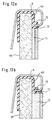
- the upper area of the support wall 68 is covered both in the embodiment according to FIG. 8a and in the embodiment according to FIG. 8b with a sound-decoupling profile element 69, which reliably prevents direct contact between the tub edge and the support wall 68.
- a groove 70 is formed, which serves to receive the front end of the tub rim 8.
- a thin bed tiling 71 is provided below the groove area of the profile element 69, a thin bed tiling 71 is provided according to FIG. 8a and a thick bed tiling 72 on the support wall 68 according to FIG. 12b.
- the gap between the tub edge 8 of the tub and the tiling 71 and 72 is sealed with a joint 73 made of permanently elastic material, in particular silicone.
- FIG. 13a shows a support member 7 according to the invention, which can be arranged between the tub floor and the screed or the raw floor.
- the support member 7 consists of an internally threaded support foot 73 into which a threaded rod 74 is screwed.
- a lock nut 75 is provided.
- the height of the support member 7 can be adjusted and adapted to the respective requirements by means of the elements 73, 74, 75.
- the height of the entire support member is adjustable in a range from 110 to 190 mm.
- the lower end of the support foot 73 is covered by a sound-decoupling cap 76. After attaching the support member to a tub, only the cap 76 is connected to the screed or the raw floor, whereby an effective sound isolation between the tub and the screed or raw floor is achieved.
- a ball joint 77 is arranged at the upper end of the threaded rod 74, via which the threaded rod 74 is coupled to a self-adhesive support disk 78 in particular.
- the support disk 78 can be adapted to the inclination of the tub floor in such a way that a full-surface contact of the support disk 78 on the tub floor results.
- the support disk 78 can be designed to be sound-decoupling at the top and / or bottom or, for example, also be connected to additional sound-decoupling disks, so that there is no structure-borne sound bridge between the tub and the support member.
- the upper end of the threaded rod 74 can be screwed into a tube with an internal thread, which is then placed directly on the tub base or via a support disk.
- a further lock nut can be provided in order to prevent an unintentional adjustment of the threaded rod 74 in the tube.
- the threaded rod 74 can also be connected at its upper end to an angular profile element, for example an angle or support element, drywall panels for dry planking being attachable to this support element (FIG. 14).
- an angular profile element for example an angle or support element, drywall panels for dry planking being attachable to this support element (FIG. 14).
- the threaded rod 74, the above-mentioned tube with internal thread and / or the support foot 73 can be encased with an insulating element, which can consist, for example, of an airborne sound-absorbing foam-fleece composite, which can be protected from damage on the outside by a grid-film layer.
- an insulating element which can consist, for example, of an airborne sound-absorbing foam-fleece composite, which can be protected from damage on the outside by a grid-film layer.
- the support members are also acoustically separated from the masonry.
- FIG. 13b shows such a support element, which is encased with an insulation element or with an insulation hose 79.
- the support member according to FIG. 13b has a support foot 80 which can be designed, for example, as a square tube. This support foot 80 is covered with the insulation hose 79 over its entire height.
- the support foot 80 is closed off with a square plug 81, on the underside of which is connected a sound-absorbing pane 82 which is preferably adhesive on one side and which decouples the support member from the screed.
- the support foot 80 is provided with a square threaded plug 83, into which a threaded rod 84 can be screwed.
- the threaded rod 84 is held in an adjustable position by means of a lock nut 85 in the support foot 80.
- the support member shown in FIG. 13b can be adjusted to different heights.
- a screw base 86 is fixedly connected to the latter, the upper side of which is covered with a further soundproof pane 87.
- This soundproof pane 87 can be used to acoustically decouple the tub rim from the support element shown.
- support wedges or support blocks made of sound-decoupling solid material can also be used.
- FIG. 14 shows a carrier system according to the invention when using the dry construction method.
- the tub 88 shown is supported on one side by a support rail 89 on the wall 90.
- At least three support members 91 are provided, which can be designed, for example, according to FIG. 13b. These support members 91 are each arranged in the corner areas of the tub edge 92 and support it against the screed.
- the tub edge 8 can also be arranged in a sound-decoupled manner in relation to the wall 90 in those areas in which there is no support rail 89.
- the support members 91 each carry two horizontally arranged dry planking rails 93, which are firmly connected to the wall 90 at their wall-side ends.
- connection point between dry cladding rails 93 and wall 90 is shown in detail in FIG. 14 at the top right.
- a soundproofing plug 94 is shown here, which is inserted into the wall 90 and into which a screw 95 can be screwed, which holds a bracket 96 with the interposition of a decoupling strip 97 on the wall 90.
- Decoupling strips 97 and soundproofing plugs 94 ensure sound decoupling of the dry planking rails 93 from the wall 90.
- a dry paneling can be attached to the dry paneling rails 93 in a conventional manner.
Landscapes
- Health & Medical Sciences (AREA)
- Public Health (AREA)
- Epidemiology (AREA)
- General Health & Medical Sciences (AREA)
- Building Environments (AREA)
- Devices For Medical Bathing And Washing (AREA)
- Bathtubs, Showers, And Their Attachments (AREA)
- Catalysts (AREA)
Abstract
Description
- Die Erfindung betrifft ein Trägersystem für Bade- oder Duschwannen, die mit einem insbesondere umlaufenden Wannenrand versehen sind, mit zumindest einer wandseitig befestigbaren Tragschiene und zwischen Wanne und Boden vorsehbaren Stützorganen.
- Bei der Montage von Bade- oder Duschwannen besteht generell das Problem, daß durch die sich beim Einbau ergebenden Verbindungen mit dem Baukörper Brücken zur Körperschallübertragung entstehen, die nicht nur unerwünscht sind, sondern es häufig auch verhindern, daß den bestehenden Vorschriften und anerkannten Regeln der Technik bezüglich der Körperschalldämmung Rechnung getragen wird.
- Auch wenn es möglich sein sollte, die geforderte Körperschalldämmung bodenseitig aufgrund der sich unterhalb eines schwimmenden Estrichs befindenden Wärme- und Trittschalldämmung in der erforderlichen Weise zu gewährleisten, so bleibt das Problem, daß über die Wannenränder und insbesondere auch über die vor der Wanne anzubringende Stützwand bzw. Schürze ausgesprochen störende Schallbrücken entstehen.
- Grundsätzlich wäre es zwar möglich, durch gezielte, aber auch aufwendige Maßnahmen bei der Montage derartiger Wannen die geforderte Schalldämmung bzw. Körperschalldämmung zu erreichen. Derartige Spezialmontagen sind jedoch auf normalen Baustellen, wo im Regelfall unter Zeit- und Kostendruck und auch mit weniger qualifiziertem Personal gearbeitet werden muß, nicht zu realisieren.
- Eine Aufgabe der Erfindung besteht darin, ein Trägersystem der eingangs genannten Art zu schaffen, das äußerst einfach handhabbar, insbesondere ohne außergewöhnliche Fachkenntnisse sachgerecht montierbar ist und dabei sicherstellt, daß störende Körperschallübertragungen in den Baukörper zuverlässig ausgeschlossen werden, wodurch schließlich eine sachgerechte und den bestehenden Bestimmungen und anerkannten Regeln der Technik entsprechende Wannenmontage ermöglicht werden soll.
- Gelöst wird diese Aufgabe nach der Erfindung im wesentlichen dadurch, daß die dem Wannenrand zugewandten Flächen der Wand und/oder der Tragschiene zumindest bereichsweise mit einer Schallentkopplungsschicht belegt sind, daß die Stützorgane zumindest ein schallentkoppelndes Dämmelement aufweisen, und daß ein schallentkoppelndes Profilelement vorgesehen ist, welches zwischen dem Wannenrand und dem ihm zugewandten Bereich einer unterhalb des Wannenrandes errichtbaren Stützwand positionierbar ist.
- Das erfindungsgemäße Prinzip besteht darin, daß konsequent an all denjenigen Stellen, an denen die Wanne mit dem Baukörper verbunden ist oder an einem mit dem Baukörper verbundenen Element abgestützt wird, eine Schallentkopplung vorgesehen ist. Da die Wannen einerseits über ihren Wannenrand an mit dem Baukörper verbundenen Tragschienen bzw. vor der Wanne errichteten Stützwänden und andererseits über denn Wannenboden auf schwimmenden Estrichen oder Rohdecken abgestützt werden, sind erfindungsgemäß an diesen Stellen zwischen der Wanne und dem sie jeweils abstützenden Element schallentkoppelnde Materialien vorgesehen.
- Die Schallentkopplung wird erfindungsgemäß konkret dadurch erreicht,
- daß die Tragschiene mit einer Schallentkopplungsschicht belegt ist, auf welcher sich der Wannenrand der eingebauten Wanne abstützt, wobei der Wannenrand ausschließlich mit der Schallentkopplungsschicht und nicht mit der Tragschiene selbst in Kontakt kommt und vom Baukörper durch schallentkoppelnde Schichten oder Profile getrennt ist,
- daß auf bzw. an einer vor der Wanne errichteten Stützwand bzw. Schürze ein schallentkoppelndes Profilelement vorgesehen ist, welches so angeordnet ist, daß der Wannenrand im Bereich der Stützwand bzw. der Schürze ausschließlich mit dem Profilelement und nicht mit der Stützwand bzw. der Schürze selbst in Kontakt kommt, und
- daß die am Wannenrand oder bodenseitig vorzusehenden Stützorgane ein die Wanne vom Estrich bzw. von der Rohdecke schallentkoppelndes Dämmelement aufweisen bzw. aus schallentkoppelndem Vollmaterial gefertigt sind.
- Durch diese konsequente Schallentkopplung kann bei Verwendung eines erfindungsgemäßen Trägersystems beispielsweise darauf verzichtet werden, Stützwände oder tragende Trockenbauwände oder den unter der Wanne befindlichen Bodenbereich gesondert vom übrigen Baukörper akustisch zu entkoppeln. Da die Schallentkopplung von Stützwänden, tragenden Trockenbauwänden oder Bodenbereichen im Vergleich zur Anbringung des erfindungsgemäßen Trägersystems einen erheblichen Aufwand darstellt, wird durch die Erfindung ein im Vergleich zum Stand der Technik sehr wirtschaftliches und einfach handzuhabendes System geschaffen, mit dem zudem eine im Vergleich zum Stand der Technik verbesserte Schallentkopplung der Wanne vom Baukörper erreichbar ist.
- Aus bisher durchgeführten Messungen ist bereits ersichtlich, daß der Schallpegel von Bade- und Duschwannen, welche von einem erfindungsgemäßen Trägersystem gehalten werden, bei einer Diagonalmessung unter 30 dB(A) liegt, während bei Systemen gemäß dem Stand der Technik Schallpegel oberhalb von 40 dB(A) gemessen werden.
- Das erfindungsgemäße Trägersystem kann für alle handelsüblichen Bade- und Duschwannen beliebiger Form eingesetzt werden, wobei diese Duschwannen aus Stahl, Gußeisen oder Kunststoff bestehen können. Bei Verwendung von rechteckigen oder quadratischen Wannen können gerade Tragschienen bzw. Profilelemente vorgesehen werden, während bei der Verwendung von anders geformten, beispielsweise runden, halbrunden oder ovalen Wannen dieser Form entsprechend angepaßte Tragschienen bzw. Profilelemente eingesetzt werden müssen.
- Als besonders vorteilhaft erweist sich der einfache Aufbau des erfindungsgemäßen Trägersystems, aufgrund dessen die Montage leicht erlern- und durchführbar ist, wobei der Montageaufwand auf ein Minimum begrenzt wird. Zudem ist durch den einfachen Aufbau gewährleistet, daß die im Rahmen des erfindungsgemäßen Trägersystems verwendeten Teile so robust sind, daß sie dem Baustellenbetrieb ohne weiteres standhalten können, ohne dabei ihre akustischen bzw. schallentkoppelnden Eigenschaften zu verlieren.
- Da die einzelnen Teile des erfindungsgemäßen Trägersystems in verschiedenen Größen zur Verfügung gestellt werden können bzw. modulartig zu verschiedenen Größen zusammensetzbar sind, entsteht bei der Montage des erfindungsgemäßen Trägersystems kein bzw. nur geringer Abfall, was unter umweltpolitischen Gesichtspunkten einen Vorteil darstellt.
- Das erfindungsgemäße Trägersystem kann zur Anbringung einer Wanne in jeder, in der sanitärtechnischen Praxis üblichen Einbauhöhe verwendet werden, da die Tragschienen jeweils in beliebiger Höhe an einer Wand angebracht werden können, die Profilelemente an Stützwänden beliebiger Höhe vorgesehen werden können und die bodenseitigen Stützorgane entweder verstellbar ausgebildet oder in verschiedenen Höhen bereitgestellt werden können, so daß unterschiedliche Abstände zwischen Estrich bzw. Rohdecke und Wannenboden realisierbar sind.
- Mit dem erfindungsgemäßen Trägersystem kann sich der Monteur ohne weiteres auf verschiedene Einbausituationen einstellen, das heißt, das Trägersystem kann sowohl vor als auch nach der Verfliesung eines Bades angebracht werden, wobei sowohl Dünn- als auch Dickbettverfliesungen zum Einsatz kommen können. Diese flexible Einsatzmöglichkeit des erfindungsgemäßen Trägersystems wird im Rahmen der Figurenbeschreibung noch näher erläutert, wobei insbesondere auch darauf Bezug genommen wird, daß Wannen problemlos mit ein-, zwei- oder dreiseitiger Wandanbindung befestigbar sind.
- Bei einer bevorzugten Ausführungsform der Erfindung wird zum einen durch die beschriebenen Maßnahmen sichergestellt, daß im Rahmen der Wandanbindung der Wanne kein direkter Kontakt zwischen Tragschiene und Wannenrand besteht, wobei zum anderen zusätzlich ein wandseitiges Schallentkopplungselement vorgesehen werden kann, welches zwischen der Wand, an der die Tragschiene befestigt ist, und dem ihr zugewandten Bereich des Wannenrandes positionierbar ist. Die auf der mit der Schallentkopplungsschicht belegten Tragschiene abgestützte Wanne kann in diesem Fall während der Montage keinesfalls so nahe an die Wand rutschen, daß sich ein direkter Kontakt zwischen Wanne und Wand ergibt, da zwischen Wanne und Wand das erwähnte zusätzliche Schallentkopplungselement vorgesehen ist. Das zusätzliche Schallentkopplungselement kann dabei auch noch dazu dienen, einen gleichmäßigen Abstand zwischen Wanne und Wand bzw. zwischen Wanne und einer nachfolgend anzubringenden Verfliesung sicherzustellen.
- Alle beschriebenen und noch zu beschreibenden, im Rahmen der Erfindung verwendbare schallentkoppelnde Materalien, insbesondere die Schallentkopplungsschicht der Tragschiene, das Dämmelement der Stützorgane, das Profilelement der Stützwand und das wandseitige Schallentkopplungselement können aus weichfederndem Material, weichem Kunststoff, Polystyrol, Kork, elastomeren Stoffen, Gummi, Naturkautschuk, Kokos, Weichschaum, insbesondere PE-Schaum, Hartschaum oder dergleichen oder aus Kombinationen dieser Materialien bestehen.
- Bei einer bevorzugten Ausführungsform der Erfindung werden die Tragschiene, das zwischen Wannenrand und Stützwand positionierbare Profilelement und/oder das wandseitige Schallentkopplungselement als in Längsrichtung aneinander anstückelbare Einzelteile ausgebildet, die insbesondere eine Länge von 60, 90 oder 120 cm aufweisen. Auf diese Weise läßt sich das erfindungsgemäße Trägersystem ohne Schwierigkeiten an verschiedene Wannengrößen anpassen und zudem in kleinen, handlichen Verpackungseinheiten vertreiben.
- Bei einer weiteren bevorzugten Ausführungsform der Erfindung sind alle Teile des erfindungsgemäßen Trägersystems feuchtigkeitsresistent ausgebildet.
- Weitere bevorzugte Ausführungsformen der Erfindung sind in den Unteransprüchen sowie im Rahmen der nachfolgenden Figurenbeschreibung angegeben.
- Die Erfindung wird im folgenden anhand von Beispielen unter Bezugnahme auf die Zeichnung erläutert; es zeigt
- Fig. 1 a
- eine Draufsicht auf eine mit einem erfindungsgemäßen Trägersystem befestigte Badewanne,
- Fig. 1 b
- einen Vertikalschnitt gemäß Schnittlinie A - A der Fig. 1 a,
- Fig. 1 c
- einen Vertikalschnitt gemäß Schnittlinie B - B der Fig. 1 a,
- Fig. 2a bis 2c
- verschiedene Einbausituationen einer Badewanne,
- Fig. 3
- eine erfindungsgemäße Anbringungsmöglichkeit einer Wanne an einer Wand mittels einer Tragschiene,
- Fig. 4a bis 4c
- unterschiedliche Ausführungsformen einer in Verbindung mit einer Tragschiene verwendbaren Schallentkopplungsschicht,
- Fig. 5
- eine weitere Anbringungsmöglichkeit einer Wanne an einer Wand mittels einer Tragschiene,
- Fig. 6a bis 6c
- verschiedene Profile eines erfindungsgemäß zwischen Wannenrand und Wand positionierbaren Schallentkopplungselements,
- Fig. 7a bis 7c
- weitere mögliche Profile eines erfindungsgemäß zwischen Wannenrand und Wand positionierbaren Schallentkopplungselements,
- Fig. 8a bis 8c
- verschiedene Abringungsmöglichkeiten einer Wanne mit aufgestelltem Wannenrand an einer Wand mittels einer Tragschiene,
- Fig. 9a bis 9c
- mögliche Ausführungsformen eines wandseitig zwischen Wand und Wannenrand positionierbaren Schallentkopplungselements,
- Fig. 10a bis 10c
- weitere Ausführungsformen einer in Verbindung mit einer Tragschiene verwendbaren Schallentkopplungsschicht,
- Fig. 11a, 11b
- erfindungsgemäße Abstützmöglichkeiten eines Wannenrandes auf einer Stützwand,
- Fig. 12a, 12b
- weitere erfindungsgemäße Abstützmöglichkeiten eines Wannenrandes auf einer Stützwand, und
- Fig. 13a
- eine mögliche Ausführungsform eines erfindungsgemäßen Stützorgans.
- Fig. 13b
- eine weitere mögliche Ausführungsform eines erfindungsgemäßen Stützorgans.
- Fig. 14
- ein erfindungsgemäßes Trägersystem bei Einsatz der Trockenbauweise.
- Fig. 1a zeigt die Draufsicht auf eine Badewanne 1, die mit einem erfindungsgemäßen Trägersystem an zwei Seiten an einer Wand 3 und an zumindest einer weiteren Seite an einer Stützwand 4, 12 abgestützt ist. Zudem ist der Wannenboden 6 über ein Stützorgan 7a gegenüber dem Estrich abgestützt. Schließlich sind noch zwei weitere Stützorgane 7b vorgesehen, die den Wannenrand in zwei seiner Eckbereiche ebenfalls gegenüber dem Estrich abstützen.
- Fig. 1b zeigt eine Schnittdarstellung entlang der Schnittlinie A-A gemäß Fig. 1a.
- Zu sehen ist die Schnittdarstellung der Badewanne 1, die mit einem erfindungsgemäßen Trägersystem einerseits über eine Tragschiene 2 an der Wand 3 und andererseits auf der der Tragschiene 2 gegenüberliegenden Stützwand 4 abgestützt ist. Zudem sind zwischen Estrich 5 und Wannenrand und/oder Wannenboden 6 drei Stützorgane 7a, 7b vorgesehen, von denen in Fig. 1 lediglich zwei sichtbar ist. Es ist auch eine Ausführungsform denkbar, bei der nur zwei oder aber auch mehr als drei Stützorgane 7a, 7b vorgesehen sind.
- Die Wanne 1 weist einen umlaufenden, nach außen umgebogenen Wannenrand 8 auf, über welchen die Wanne 1 an der Stützwand 4, an der Tragschiene 2 und an den Stützorganen 7b abgestützt ist.
- Falls bei einer alternativen Anwendungsform keine Stützwand vorhanden sein sollte (sog. Trockenbauweise, vgl. auch Fig. 14), kann der Wannenrand 8 auch nur an einem oder mehreren Stützorganen abgestützt werden, die in ihrem Aufbau den in Fig. 1 dargestellten Stützorganen 7b entsprechen können, jedoch in ihrer Länge dem Abstand Estrich 5 - Wannenrand 8 angepaßt werden müssen.
- Die Tragschiene 2 besitzt ein Z-förmiges Profil und ist beispielsweise mittels einer Schraubverbindung an der Wand 3 angebracht. Die an der Wand 3 angebrachte Tragschiene 2 bildet gemeinsam mit der Wand 3 eine im Querschnitt U-förmige, nach oben offene Aufnahme für eine Schallentkopplungsschicht 9, die in ihrem Profil an die Tragschiene angepaßt ist und an der der Wannenrand 8 abgestützt ist.
- Die Wand 3 ist mit einer Verfliesung 10 versehen, welche oberhalb des Wannenrandes 8 endet.
- Zwischen Verfliesung 10 und Wannenrand 8 bzw. zwischen Wand 3 und Wannenrand 8 ist ein im Querschnitt L-förmiges Schallentkopplungselement 11 vorgesehen, welches eine zusätzliche Schallentkopplung der Wanne 1 gegenüber der Wand 3 bzw. der Verfliesung 10 bewirkt und zudem einen konstanten und gleichmäßigen Abstand zwischen Wannenrand 8 und Verfliesung 10 bzw. zwischen Wannenrand 8 und Wand 3 sicherstellt.
- Die ebenfalls mit einer Verfliesung 12 versehene Stützwand 4 ist in ihrem oberen Bereich mit einem schallentkoppelnden Profilelement 13 belegt, welches in seiner Form der verfliesten Stützwand 2 angepaßt ist und sicherstellt, daß ein direkter Kontakt zwischen Wannenrand 8 bzw. Wanne 1 und Stützwand 4 bzw. Verfliesung 12 vermieden wird.
- Die Stützorgane 7a, 7b weisen zumindest ein schallentkoppelndes Dämmelement auf, welches gewährleistet, daß zwischen dem Wannenboden 6 und dem Estrich 5 bzw. zwischen dem Wannenrand 8 und dem Estrich 5 keine Körperschallbrücken entstehen können. Eine mögliche Ausbildungsform eines Stützorgans 7a, 7b ist beispielsweise in den Fig. 13a und 13b gezeigt.
- Bei einer bevorzugten Ausführungsform der Erfindung werden die Stützorgane auf der der Tragschiene 2 abgewandten Seite der Wanne bzw. des Wannenbodens 6 angeordnet. Auf diese Weise wird auf der der Tragschiene 2 zugewandten Seite des Wannenbodens 6 ausreichend Platz für die Vorsehung von Rohrleitungen 14 geschaffen. Die Stützorgane werden dabei jeweils ungefähr im gleichen Abstand zur Wand 3 in Längsrichtung der Wanne versetzt zueinander angeordnet.
- Fig. 1c entspricht im wesentlichen Fig. 1b, es sind hier lediglich die in den Eckbereichen der Wanne 1 angeordneten Stützorgane 7b vollständig zu sehen. Diese Stützorgane 7b sind in ihrer Länge variabel und somit an den Abstand zwischen Wannenrand 8 und Estrich 5 anpaßbar.
- Fig. 2a bis 2c zeigen verschiedene Situationen, die beim Einbau einer Badewanne in einem Badezimmer gegeben sein können. In Fig. 2a liegt die Wanne 1 lediglich mit einer ihrer Längsseiten an einer Wand 15 an. Bei dieser einseitigen Wandanbindung ist die Wanne 1 an der Wand 15 mittels einer erfindungsgemäßen Tragschiene gehalten.
- Die anderen drei Seiten der Wanne 1 sind dabei auf unter ihr errichteten Stützwänden abgestützt.
- Fig. 2b zeigt eine zweiseitige Wandanbindung der Wanne 1 an die Wände 15 und 16, wobei hier die beiden den Wänden 15 und 16 gegenüberliegenden Seiten der Wanne 1 jeweils von Stützwänden getragen werden.
- Fig. 2c zeigt eine dreiseitige Wandanbindung der Wanne 1 an die Wände 15, 16 und 17, wobei die Wanne 1 lediglich an der der Wand 16 gegenüberliegenden Seite von einer Stützwand getragen wird.
- Bei einer Einbausituation gemäß den Fig. 2b und 2c muß die Wanne an zumindest einer der Wände 15, 16 bzw. 15, 16, 17 mittels einer Tragschiene gehalten werden, es ist jedoch auch möglich, daß die Wanne 1 an mehreren der Wände 15, 16 bzw. 15, 16, 17 mittels jeweils einer Tragschiene gehalten ist.
- Die Anzahl der verwendeten Tragschienen bei einer Einbausituation gemäß den Fig. 2b und 2c ist beispielsweise vom verwendeten Wannenmaterial abhängig, wobei für Kunststoffwannen in der Regel eine allseitige Randunterstützung erforderlich ist, während bei Wannen aus Stahl oder Guß auch eine Abstützung an lediglich einer Stützwand und einer gegenüberliegenden Wand ausreichen kann.
- Bei Einsatz einer Trockenbeplankung (Fig. 14) anstelle einer Einmauerung ist es nötig, eine Wanne mit ihrem Wannenrand über mindestens zwei Stützorgane bodenseitig und am Rand abzustützen. Weiterhin ist der Wannenboden über mindestens ein Stützorgan bodenseitig abzustützen. Mögliche Ausführungsformen geeigneter Stützorgane sind in Zusammenhang mit Fig. 13a und 13b beschrieben.
Zusätzlich muß für eine schallentkoppelnde Wandbefestigung gesorgt werden, die beispielsweise mit einem entsprechend ausgebildeten Spannanker (DE 43 24 133.6, EP 94 110 896.1) oder einer ähnlichen Vorrichtung bewerkstelligbar ist. - Fig. 3 zeigt eine Detailansicht des erfindungsgemäßen Trägersystems, bei der ein in herkömmlicher Weise nach außen umgebogener Wannenrand 8 über eine Tragschiene 2 an einer Wand 3 befestigt ist.
- Die Tragschiene 2 ist entsprechend Fig. 1 ausgebildet und schafft auf diese Weise gemeinsam mit der Wand 3 eine nach oben offene Aufnahme für eine im Querschnitt im wesentlichen U-förmige Schallentkopplungsschicht 18, welche wiederum eine nach oben offene Aufnahme für den Wannenrand 8 aufweist.
- Für die Herstellung der Tragschiene 2 eignet sich beispielsweise verzinkter Stahl, Aluminium und dergleichen, wobei vorzugsweise darauf zu achten ist, daß das verwendete Material feuchtigkeitsresistent ist.
- Die nach oben offene und zur Aufnahme des Wannenrandes 8 geeignete Ausnehmung der Schallentkopplungsschicht 18 ist mit einer Lastverteilungsschicht 19 belegt, die insbesondere aus Hartkunststoff, Aluminium oder dergleichen gefertigt sein kann. Die Lastverteilungsschicht 19 wird vorzugsweise in die Ausnehmung der Schallentkopplungsschicht 18 eingeklebt oder eingepreßt. Durch die Lastverteilungsschicht 19 kann die Wannenlast bzw. die Gesamtlast von Wanne, Wasser und Benutzer gleichmäßig auf die Länge der Tragschiene 2 verteilt werden.
- Die Lastverteilungsschicht 19 ist nicht erforderlich, wenn als Schallentkopplungsschicht 18 ein Material verwendet wird, das sowohl gute schallentkoppelnde Eigenschaften aufweist als auch mechanisch belastbar ist, ohne daß sich eine zu starke Verformung ergibt. Diesbezüglich bietet sich beispielsweise die Verwendung eines Polyurethan-Elastomers an.
- Zwischen der Wand 3 und dem ihr zugewandten Bereich des Wannenrandes 8 ist ein Schallentkopplungselement 20 vorgesehen, welches einen L-förmigen Querschnitt aufweist, wobei sich ein Schenkel dieses Schallentkopplungselements 20 horizontal oberhalb des Wannenrandes 8 und der andere Schenkel vertikal zwischen Wannenrand 8 und Wand 3 erstreckt.
- Das Schallentkopplungselement 20 übernimmt zweierlei Aufgaben:
Einerseits bewirkt das Schallentkopplungselement 20 eine wirksame Schallentkopplung zwischen Wannenrand 8 und Wand 3. Es ist durch die Vorsehung des Schallentkopplungselements 20 unmöglich, daß die Wanne beispielsweise derart verrutscht, daß der Wannenrand 8 direkt an der Wand 3 zur Anlage kommt und auf diese Weise eine Schallbrücke entsteht. - Andererseits gewährleistet das Schallentkopplungselement, welches über seine gesamte Länge einen konstanten Querschnitt aufweist, daß zwischen dem Wannenrand 8 und der Wand 3 ein gleichmäßiger Abstand eingehalten wird und zudem auch ein konstanter Abstand einer oberhalb des Wannenrandes 8 an der Wand 3 angebrachten Verfliesung 21 zum Wannenrand 8 gewährleistet ist.
- Bevorzugte Ausführungsformen des Schallentkopplungselements 20 werden nachfolgend im Zusammenhang mit den Fig. 5 bis 9 beschrieben.
- Fig. 4 zeigt mögliche Ausbildungsformen der Schallentkopplungsschicht 18 gemäß Fig. 3. Um die schalldämmende Wirkung der Schallentkopplungsschicht 18 zu erhöhen, kann sie mit Öffnungen versehen werden, welche sich insbesondere in Richtung ihrer Längsachse oder auch quer dazu erstrecken. Diese Öffnungen, die auch in anderen schallentkoppelnden Elementen des erfindungsgemäßen Trägersystems enthalten sein können, weisen bevorzugt folgende Querschnitte auf:
- Fig. 4a zeigt beispielsweise Öffnungen in Form von Langlöchern 22, Fig. 4b zeigt Öffnungen in Form von Bohrungen 23 und Fig. 4c zeigt Öffnungen in Form von rechteckigen Durchbrechungen 24. Es lassen sich jedoch auch beliebige andere Formen der Öffnungen 22, 23, 24 realisieren.
- Fig. 5 zeigt ein Ausführungsbeispiel, bei dem eine Wanne mit ihrem Wannenrand 8 an einer bereits fertig verfliesten Wand 25 mittels einer Tragschiene 2 angebracht wird.
- Tragschiene 2, Schallentkopplungselement 18' und Lastverteilungsschicht 19' sind analog zu Fig. 3 ausgebildet, wobei aus Fig. 5 ersichtlich ist, daß bezüglich des Querschnittes der Schallentkopplungsschicht 18 und der Lastverteilungsschicht 19 gemäß Fig. 3 auch andere Querschnittsformen möglich sind.
- Das Schallentkopplungselement 20' dient bei der Ausbildungsform gemäß Fig. 5 einerseits der Schallentkopplung von Wannenrand 8 und Wand 25 und stellt andererseits einen konstanten Abstand zwischen Wannenrand 8 und Wand 25 sicher. Der Querschnitt des Schallentkopplungselements 20 kann bei der Ausbildungsform gemäß Fig. 5 rechteckig gewählt werden, da das Schallentkopplungselement 20' im Gegensatz zur Ausbildungsform gemäß Fig. 3, bei dem es einen L-förmigen Querschnitt aufweist, nicht für einen konstanten Vertikal-Abstand zwischen Verfliesung und Wannenrand 8 sorgen muß, da die Wand 25 gemäß Fig. 5 bereits vollständig verfliest ist.
- Um ein Eindringen von Spritz- oder Schwallwasser in den zwischen Wannenrand 8 und Wand 25 bestehenden Zwischenraum zu verhindern und um ein für den Benutzer gefälliges Aussehen der Gesamtanordnung zu erzielen, ist oberhalb des Schallentkopplungselements 20' zwischen Wannenrand 8 und Wand 25 eine dauerelastische, beispielsweise aus Silikon bestehende Fuge 26 vorgesehen. Durch die Fuge kann beispielsweise auch eine eventuell erforderliche Farbanpassung vorgenommen werden.
- Ein wesentlicher Vorteil des erfindungsgemäßen Systems besteht darin, daß die Fuge 26 im Vergleich zum Stand der Technik nun keine akustische, schallentkoppelnde Funktion mehr übernehmen muß und beim Anbringen der Fuge 26 keine Rücksicht auf derartige schallentkoppelnde Eigenschaften zu nehmen ist, da die Schallentkopplung bereits durch die Vorsehung der Schallentkopplungsschicht 18' und des Schallentkopplungselements 20' sichergestellt ist.
- Fig. 6a bis 6c zeigen mögliche Querschnittsformen eines zwischen Wannenrand 8 und Wand 3 vorsehbaren Schallentkopplungselements. Das Schallentkopplungselement 27 gemäß Fig. 6a ist so bemessen, daß es im Zusammenhang mit einer an der Wand 3 angebrachten Dickbettverfliesung 28 verwendet werden kann.
- In dem zwischen Fliesen und Wand befindlichen oberen Bereich gibt das Schallentkopplungselement 27 den entsprechenden Abstand vor. Ebenso gibt es einen bei der Dickbettverfliesung gemäß Fig. 6a vergleichsweise kleineren Abstand zwischen Wannenrand 8 und Wand 3 in seinem unteren Bereich vor.
- Das Schallentkopplungselement 27' gemäß Fig. 6b entspricht im wesentlichen dem Schallentkopplungselement 27 gemäß Fig. 6a, wobei gemäß Fig. 6b in dem oberhalb des Wannenrandes 8 gelegenen und den Fliesen zugewandten Bereich eine Ausnehmung 29 vorgesehen ist. Auch das Schallentkopplungselement 27' ist für eine Dickbettverfliesung 28 geeignet.
- Fig. 6c zeigt ein Schallentkopplungselement 27'' welches für eine Dünnbettverfliesung 30 geeignet ist. Die Horizontalabmessungen des Schallentkopplungselements 27'' in dem zwischen Wand 3 und Fliesen befindlichen Bereich ist hier im Vergleich zu den Fig. 6a und 6b entsprechend geringer.
- Alle Schallentkopplungselemente 27, 27', 27'' gemäß den Fig. 6a bis 6c sind mit einer sich horizontal oberhalb des Wannenrandes 8 von der Wand 3 wegerstreckenden und in ihrem Endbereich abgerundeten Dichtlippe 31 versehen, welche dafür sorgt, daß kein Schwall- und Spritzwasser in den zwischen Wannenrand 8 und Wand 3 befindlichen Bereich eindringen kann. Die Vorsehung der Dichtlippe 31, welche insbesondere unter Vorspannung auf der Oberseite des Wannenrandes 8 aufliegt, macht die Verwendung einer zusätzlichen Silikonfuge überflüssig, wodurch der Montageaufwand weiter verringert wird.
- Die Fig. 7a bis 7c zeigen weitere mögliche Ausbildungsformen von Schallentkopplungselementen gemäß Fig. 6.
- Die Schallentkopplungselemente 33 bis 35 gemäß den Fig. 7a bis 7c sind zur Verwendung mit einer nachträglich zu fliesenden Wand geeignet sind.
- Der obere Bereich der Schallentkopplungselemente 33 bis 35 ist jeweils so ausgebildet, daß er bei eingesetztem Schallentkopplungselement im wesentlichen das Aussehen einer Fuge aufweist, die sich entlang der Wand 3 und entlang des Wannenrandes 8 verjüngt.
- Durch die Schallentkopplungselemente 33 bis 35 wird eine Abdichtung des zwischen Wannenrand 8 und Wand 3 bestehenden Spaltes erzielt.
- Fig. 7a zeigt ein Schallentkopplungselement 33, welches eine unter Vorspannung auf den Wannenrand 8 aufliegende, sich verjüngende Dichtlippe 37 aufweist.
- Eine entsprechende Dichtlippe 37' weist auch das Schallentkopplungselement 34 gemäß Fig. 7b auf, wobei die beiden nach dem Einbau rechtwinklig zueinander verlaufenden Schenkel des Schallentkopplungselements 34 vor dem Einbau beispielsweise in einem spitzeren Winkel zueinander verlaufen können, um so nach der Montage ebenfalls eine Vorspannung der Dichtlippe 37 gegenüber dem Wannenrand 8 zu erreichen.
- Mit der beschriebenen Vorspannung gemäß Fig. 7a und 7b läßt sich eine besonders gute Dichtwirkung erreichen.
- Das Schallentkopplungselement 35 gemäß Fig. 7c weist eine sich von dessen oberem Rand vertikal nach unten erstreckende Nut 38 auf, in die eine Fliese 39 eingreifen kann.
- Wenn die Breite der Nut 38 an die Dicke der Fliese 39 angepaßt ist, läßt sich so eine besonders gute Abdichtung zwischen der verfliesten Wand und dem Wannenrand 8 erzielen.
- Fig. 8 zeigt im Gegensatz zu den bisher beschriebenen Beispielen die wandseitige Abstützung eines Wannenrandes 40, welcher nicht in herkömmlicher Weise nach außen und unten umgebogen, sondern als aufgestellter Wannenrand 40 ausgebildet ist. Auch in Verbindung mit solchen Stützrändern 40 läßt sich das erfindungsgemäße Trägersystem auf vorteilhafte Weise verwenden.
- Bei einem aufgestellten Wannenrand 40 bietet sich beim Einsatz einer ebenfalls Z-förmigen Tragschiene 2 die Verwendung einer im Querschnitt im wesentlichen L-förmigen Schallentkopplungsschicht 41 an, die mit ihrem dünneren, vertikal nach oben verlaufenden Schenkel den Abstand des Wannenrandes 40 zur Wand 3 festlegt.
- Die Schallentkopplungsschicht 41 kann bei der bevorzugten Ausführungsform gemäß Fig. 8a entsprechend den bereits beschriebenen Beispielen mit einer Lastverteilungsschicht 42 belegt werden, welche nun jedoch entsprechend an die Form der Schallentkopplungsschicht 41 angepaßt ist und demzufolge ebenfalls einen L-förmigen Querschnitt aufweist.
- Oberhalb des nach oben umgebogenen Endes des Wannenrandes 40 ist an der Wand 3 ein Z-förmiges Halteprofil 43 befestigt, welches den nach oben umgebogenen Bereich des Wannenrandes 40 von oben her unter Ausbildung eines Spaltes zwischen Wannenrand 40 und Halteprofil 43 übergreift.
- In dem erwähnten Spalt ist ein Schallentkopplungselement 44 angeordnet, welches sich in diesem Spalt vertikal und oberhalb des Wannenrandes 40 horizontal zur Wand 3 hin erstreckt, so daß das Schallentkopplungselement 44 insgesamt einen L-förmigen Querschnitt aufweist.
- An der Wand 3 angebrachte Fliesen 45 enden unmittelbar oberhalb des horizontal verlaufenden Bereichs des Halteprofils 43, so daß dieser Bereich des Halteprofils 43, welcher in einem konstanten Vertikalabstand zum Wannenrand 42 verläuft, für einen konstanten Abstand der Fliesen 45 zum Wannenrand 40 sorgt.
- Ein eventuell zwischen Fliesen 45 und Halteprofil 43 vorhandener Spalt kann mittels einer insbesondere aus Silikon bestehenden Fuge 46 abgedichtet werden.
- Die Horizontalabmessungen von Halteprofil 43 und Schallentkopplungselement 44 können auch gemäß Fig. 8b entsprechend kleiner gewählt werden, um so einen raumseitig bündigen Übergang zwischen Fliesen 45' und dem unteren, vertikal verlaufenden Bereich des Halteprofils 43' zu schaffen. Bei diesem bündigen Übergang kann auf die Verwendung einer Silikonfuge verzichtet werden.
- Die in den Fig. 8a und 8b dargestellten Ausbildungsformen sind jeweils für die Verwendung mit einer Dünnbett-Verfliesung geeignet.
- Fig. 8c zeigt eine Ausbildungsform, welche für die Verwendung mit einer Dickbett-Verfliesung geeignet ist. Hier sind die Horizontalabmessungen von Halteprofil 43'' und Schallentkopplungselement 44'' entsprechend größer gewählt.
- Die Fig. 9a bis 9c zeigen mögliche Ausbildungsformen eines Schallentkopplungselements, wie es beispielsweise in einer Vorrichtung gemäß Fig. 3 verwendet werden kann .
- Um der jeweiligen Dicke der verwendeten Fliesen bzw. einer wahlweise verwendbaren Dünn- oder Dickbett-Verfliesung Rechnung tragen zu können, kann das Schallentkopplungselement 47 gemäß Fig. 9a mit einer Sollbruchstelle 48 versehen werden, an der ein Teil des Schallentkopplungselements abgebrochen werden kann, um so dessen horizontal verlaufenden Bereich entsprechend den jeweiligen Anforderungen verkürzen zu können. Es ist ebenso möglich, beabstandet voneinander mehrere Sollbruchstellen 48 vorzusehen.
- Falls auf die Sollbruchstellen 48 vollständig verzichtet wird, kann das Schallentkopplungselement 47 vor oder nach der Montage beispielsweise auch mittels eines Messers entsprechend den jeweiligen Anforderungen abgeschnitten werden.
- Fig. 9b zeigt ein Schallentkopplungselement 49, welches einen im wesentlichen L-förmigen Querschnitt aufweist und aus zwei Teilen 50, 51 besteht.
- Der sich im wesentlichen vertikal erstreckende Teil 51 weist eine horizontale Nut 52 auf, in die eine am sich im wesentlichen horizontal erstreckenden Teil angebrachte Feder 53 eingreift. Die Feder 53 ist dabei in der Nut 52 horizontal verschieblich.
- Durch diese Ausbildung ist es möglich, die horizontalen Abmessungen des Schallentkopplungsements 49 durch ein relatives Verschieben der beiden Teile 50, 52 zueinander entsprechend den jeweiligen Anforderungen einzustellen.
- Alternativ ist es möglich, gemäß Fig. 9 c die beiden Schenkel 50', 51' des Schallentkopplungslements durch eine Klebung 50a miteinander zu verbinden und bei Bedarf (z.B. nach fertiger Verfliesung) einen nicht benötigten Schenkel abzureißen.
- Bezüglich des zwischen Wand und Wannenrand vorzusehenden Schallentkopplungselements sei an dieser Stelle ausdrücklich erwähnt, daß sich dieses auch ohne die sonstigen Merkmale der Erfindung sinnvoll bei aus dem Stand der Technik bekannten Trägersystemen einsetzen läßt, wobei sich bereits allein durch den Einsatz dieses Schallentkopplungselements eine wesentliche Verbesserung der erzielbaren Schalldämmeigenschaften erreichen läßt. Im Rahmen der Erfindung wird auch Schutz dafür beansprucht, das erwähnte Schallentkopplungselement nur in Kombination mit aus dem Stand der Technik bekannten Trägersystemen einzusetzen.
- Die Fig. 10a bis 10c zeigen weitere mögliche Ausbildungsformen einer Schallentkopplungsschicht, mit welcher eine Tragschiene 2 belegt werden kann.
- Die Schallentkopplungsschichten gemäß den Fig. 10a bis 10c weisen alle folgenden Schichtaufbau auf:
Die äußerste und direkt mit der Tragschiene bzw. der Wand 3 in Kontakt stehende Schicht ist durch eine insbesondere durch eine Gitterstruktur verstärkte Folie 54 gebildet. Innenliegend schließt sich eine Faserschicht 55 an, an deren Innenseite wiederum eine Schaumstoffschicht 56 angeordnet ist. - Der Schichtenverbund 54, 55, 56 besitzt einen im wesentlichen U-förmigen Querschnitt, dessen freier innerer Querschnitt in seinem unteren Bereich mit einer schalldämmenden Polsterlage 57 ausgefüllt ist.
- Die Ausführungsform gemäß Fig. 10b entspricht im wesentlichen der beschriebenen Ausführungsform gemäß Fig. 10a mit dem Unterschied, daß die innenliegende Schaumstoffschicht 56' gemäß Fig. 10b mit einem Rillenprofil versehen ist.
- Die Oberseite der Polsterlage 57, auf der schließlich der in Fig. 10 nicht dargestellte Wannenrand der Wanne abgelegt wird, kann entsprechend Fig. 10a mit einer beispielsweise aus Hartkunststoff oder Aluminium bestehenden Lastverteilungsschicht 58 belegt sein, welche dafür sorgt, daß sich die durch die Wanne auf die Polsterlage 57 ausgeübte Kraft gleichmäßig verteilt.
- Oberhalb der Lastverteilungsschicht 58 kann vorzugsweise eine weitere Schicht bzw. ein Schichtverbund 59 angeordnet sein, welcher aus einer Schaumstoff-, Faser- und/oder Folienschicht besteht, wobei die Folienschicht gitterverstärkt ausgebildet sein kann.
- Die Schichten 58, 59 können ebenso bei den Ausbildungsformen gemäß Fig. 10b und 10c vorgesehen werden.
- Bei der Ausführungsform gemäß Fig. 10c erstreckt sich der wandseitige Vertikalschenkel der Schallentkopplungsschicht weiter nach oben als bei den Ausführungsformen gemäß den Fig. 10a und 10b, wobei dieser verlängerte Schenkel in seinem oberen Bereich rechtwinklig von der Wand 3 weg abgeknickt ist, wodurch sich eine Auflagefläche bzw. Abstandsmarkierung 60 für oberhalb der Auflagefläche bzw. Abstandsmarkierung 60 nachträglich an der Wand 3 anzubringende Fliesen ergibt.
- Zugleich bildet der verlängerte vertikale Bereich 61 eine Schallentkopplungsschicht zwischen dem auf der Polsterlage 57 abzustützenden Rand der Wanne und der Wand 3.
- Auf diese Weise übernimmt der in Fig. 10c dargestellte und entsprechend ausgeformte Schichtverbund zugleich die Aufgaben der erfindungsgemäßen, mit der Tragschiene gekoppelten Schallentkopplungsschicht und dem wandseitigen Schallentkopplungselement. Durch diese einstückige Ausführung von Schallentkopplungsschicht und Schallentkopplungselement wird die Montage zusätzlich vereinfacht, da die Anzahl der benötigten Teile entsprechend reduziert ist. Zudem ergibt sich eine Kostenersparnis bei der Herstellung.
- Die Schichtverbundmaterialien gemäß Fig. 10, gegebenenfalls einschließlich der Polsterlage 57, kann man auf besonders vorteilhafte und einfache Weise dadurch erhalten, daß man eine aus dem Stand der Technik mittlerweile bekannte Kompaktdämmhülse zur Dämmung von Rohrleitungen entsprechend aufschneidet. So kann zur Herstellung der benötigten Dämmaterialien auf handelsübliche Produkte zurückgegriffen werden, ohne daß ein neuer Herstellungsprozeß nötig ist.
- Fig. 11 zeigt die Abstützung eines Wannenrandes 62 einer handelsüblichen Kunststoffwanne auf einer unterhalb des Wannenrandes 62 vor der Wanne errichteten Stützwand 63, welche mit einer Dünnbett-Verfliesung 64 versehen ist.
- Das obere Ende der Stützwand 63 ist mit einem schallentkoppelnden Profilelement 65 U-förmigen Querschnitts belegt, dessen wannenaußenseitiger Vertikalschenkel stirnseitig an die Verfliesung 64 angrenzt.
- Der vertikal verlaufende außenseitige Bereich des Wannenrandes 62 endet kurz oberhalb der Verfliesung 64, so daß zwischen der Stirnseite des Wannenrandes 62 und der Verfliesung 64 ein Spalt ausgebildet wird.
- Dieser Spalt kann mit einer insbesondere aus Silikon bestehenden dauerelastischen Verfugung 66 versehen werden.
- Die Gesamtstärke von Profilelement 65 und Wannenrand 62 entspricht der Stärke der Dünnbett-Verfliesung 64, so daß sich wannenaußenseitig zwischen Wannenrand 62 und Verfliesung 64 ein bündiger Übergang ergibt.
- Fig. 11b zeigt eine Ausführungsform, bei der im Unterschied zu Fig. 11a eine dünnere Stützwand 63', dafür jedoch eine Dickbett-Verfliesung 64' verwendet ist.
- Das Profilelement 65 gemäß Fig. 11b weist die gleichen Abmessungen auf, wie das Profilelement 65 gemäß Fig. 11a.
- Da in Fig. 11b eine dünnere Stützwand 63' zum Einsatz kommt, bildet sich zwischen dem wannenaußenseitigen Vertikalschenkel des Profilelements 65 und dem gegenüberliegenden Bereich der Stützwand 63' ein Hohlraum 67, der sich jedoch nicht störend auswirkt.
- Fig. 12a und 12b zeigen jeweils die Abstützung eines nach außen und nach unten umgebogenen Wannenrandes 8 einer herkömmlichen Stahlbadewanne auf einer Stützwand 68.
- Der obere Bereich der Stützwand 68 ist sowohl in der Ausführungsform gemäß Fig. 8a als auch in der Ausführungsform gemäß Fig. 8b mit einem schallentkoppelnden Profilelement 69 belegt, welches zuverlässig einen direkten Kontakt zwischen Wannenrand und Stützwand 68 verhindert.
- An den der Wanne abgewandten Vertikalschenkel des Profilelements 69 ist eine Nut 70 angeformt, welche zur Aufnahme des stirnseitigen Endes des Wannenrandes 8 dient.
- Unterhalb des Nutbereichs des Profilelements 69 ist gemäß Fig. 8a eine Dünnbett-Verfliesung 71 und gemäß Fig. 12b eine Dickbett-Verfliesung 72 an der Stützwand 68 vorgesehen.
- Der zwischen dem Wannenrand 8 der Wanne und der Verfliesung 71 bzw. 72 bestehende Spalt ist jeweils mit einer Fuge 73 aus dauerelastischem Material, insbesondere aus Silikon abgedichtet.
- Fig. 13a zeigt ein erfindungsgemäßes Stützorgan 7, welches zwischen dem Wannenboden und dem Estrich bzw. dem Rohfußboden angeordnet werden kann.
- Das Stützorgan 7 besteht aus einem mit einem Innengewinde versehenen Stützfuß 73, in welchen eine Gewindestange 74 eingeschraubt ist.
- Um ein ungewolltes Verstellen der Gewindestange 74 im Stützfuß 23 zu verhindern, ist eine Kontermutter 75 vorgesehen.
- Mittels der Elemente 73, 74, 75 kann die Höhe des Stützorgans 7 verstellt und an die jeweiligen Anforderungen angepaßt werden. Insbesondere ist die Höhe des gesamten Stützorgans in einem Bereich von 110 bis 190 mm verstellbar.
- Das untere Ende des Stützfußes 73 ist mittels einer schallentkoppelnden Kappe 76 abgedeckt. Nach Anbringung des Stützorgans an einer Wanne steht ausschließlich die Kappe 76 mit dem Estrich bzw. dem Rohfußboden in Verbindung, wodurch eine wirksame Schallentkopplung zwischen Wanne und Estrich bzw. Rohfußboden erreicht wird.
- Am oberen Ende der Gewindestange 74 ist ein Kugelgelenk 77 angeordnet, über welches die Gewindestange 74 mit einer insbesondere selbstklebenden Stützscheibe 78 gekoppelt ist.
- Durch das Kugelgelenk 77 kann die Stützscheibe 78 jeweils an die Neigung des Wannenbodens derart angepaßt werden, daß sich eine vollflächige Anlage der Stützscheibe 78 am Wannenboden ergibt. Die Stützscheibe 78 kann oben und/oder unten schallentkoppelnd ausgebildet oder beispielsweise auch mit zusätzlichen schallentkoppelnden Scheiben verbunden werden, so daß keine Körperschallbrücke zwischen Wanne und Stützorgan besteht.
- Bei einer alternativen und stabileren Ausführungsform des Stützorgans wird kein Kugelgelenk vorgesehen, sondern das obere Ende des Stützorgans direkt oder lediglich über eine beispielsweise schallentkoppelnde Stützscheibe am Wannenboden angelegt (Fig. 13 b).
- Das obere Ende der Gewindestange 74 kann bei einer in Fig. 13a nicht dargestellten Ausführungsform in ein Rohr mit Innengewinde eingeschraubt werden, das dann direkt oder über eine Stützscheibe am Wannenboden angelegt wird. Um auch hier ein ungewolltes Verstellen der Gewindestange 74 im Rohr zu verhindern, kann eine weitere Kontermutter vorgesehen werden.
- Die Gewindestange 74 kann an ihrem oberen Ende auch mit einem eckigen Profilelement, beispielsweise einem Winkel- bzw. Stützelement verbunden werden, wobei an diesem Stützelement Trockenbauplatten für eine Trockenbeplankung befestigbar sind (Fig. 14).
- Die Gewindestange 74, das vorstehend erwähnte Rohr mit Innengewinde und/oder der Stützfuß 73 können mit einem Dämmelement ummantelt werden, das beispielsweise aus einem luftschalldämmenden Schaum-Vlies-Verbund bestehen kann, welcher außenseitig durch eine Gitter-Folien-Lage gegen Beschädigungen schützbar ist. Auf diese Weise werden zusätzlich die Stützorgane akustisch vom Mauerwerk getrennt.
- Fig. 13b zeigt ein derartiges Stützelement, das mit einem Dämmelement bzw. mit einem Dämmschlauch 79 ummantelt ist.
- Das Stützorgan gemäß Fig. 13b weist einen Stützfuß 80 auf, der beispielsweise als Vierkantrohr ausgebildet sein kann. Dieser Stützfuß 80 ist über seine gesamte Höhe mit dem Dämmschlauch 79 ummantelt.
- An seinem unteren Ende ist der Stützfuß 80 mit einem Vierkantstopfen 81 abgeschlossen, an dessen Unterseite sich eine bevorzugt einseitig klebende Schallschutzscheibe 82 anschließt, die das Stützorgan gegenüber dem Estrich schallentkoppelt.
- An seinem oberen Ende ist der Stützfuß 80 mit einem Vierkant-Gewindestopfen 83 versehen, in welchen eine Gewindestange 84 einschraubbar ist. Die Gewindestange 84 wird in einer einstellbaren Position mittels einer Kontermutter 85 im Stützfuß 80 gehalten.
- Durch das verschieden tiefe Einschrauben der Gewindestange 84 in den Stützfuß 80 läßt sich das in Fig. 13b dargestellte Stützorgan auf verschiedene Höhen einstellen.
- Am oberen Ende der Gewindestange 84 ist fest mit diesem ein Schraubfuß 86 verbunden, dessen Oberseite mit einer weiteren Schallschutzscheibe 87 belegt ist. Diese Schallschutzscheibe 87 kann dazu dienen, den Wannenrand gegenüber dem dargestellten Stützorgan schalltechnisch zu entkoppeln.
- Anstelle eines Stützorgans gemäß Fig. 13a, b können ebenfalls aus schallentkoppelndem Vollmaterial gefertigte Stützkeile oder Stützblöcke eingesetzt werden.
- Fig. 14 zeigt ein erfindungsgemäßes Trägersystem bei Einsatz der Trockenbauweise.
- Die dargestellte Wanne 88 ist an einer Seite über eine Tragschiene 89 an der Wand 90 abgestützt.
- Weiterhin sind zumindest drei Stützorgane 91 vorgesehen, die beispielsweise gemäß Fig. 13b ausgebildet sein können. Diese Stützorgane 91 sind jeweils in den Eckbereichen des Wannenrandes 92 angeordnet und stützen diesen gegenüber dem Estrich ab.
- Zwischen Tragschiene 89 und Wand 90 bzw. zwischen Tragschiene 89 und Wannenrand 92 besteht eine vorstehend erläuterte Schallentkopplung. Weiterhin kann der Wannenrand 8 gegenüber der Wand 90 auch in denjenigen Bereichen, in denen keine Tragschiene 89 vorhanden ist, schallentkoppelt angeordnet sein.
- Die Stützorgane 91 tragen jeweils zwei horizontal übereinander angeordnete Trockenbeplankungsschienen 93, die an ihren wandseitigen Enden fest mit der Wand 90 verbunden sind.
- Die Verbindungsstelle zwischen Trockenbeplankungsschienen 93 und Wand 90 ist in Fig. 14 rechts oben im Detail dargestellt. Es ist hier ein Schallschutzdübel 94 gezeigt, welcher in die Wand 90 eingesetzt wird und in den eine Schraube 95 einschraubbar ist, die einen Haltewinkel 96 unter Zwischenschaltung eines Entkopplungsstreifens 97 an der Wand 90 hält.
- Entkopplungsstreifen 97 und Schallschutzdübel 94 sorgen für eine Schallentkopplung der Trockenbeplankungsschienen 93 gegenüber der Wand 90.
- An den Trockenbeplankungsschienen 93 kann in üblicher Weise eine Trockenbeplankung angebracht werden.
-
- 1
- Badewanne
- 2
- Tragschiene
- 3
- Wand
- 4
- Stützwand
- 5
- Estrich
- 6
- Wannenboden
- 7a
- Stützorgane
- 7b
- Stützorgane
- 8
- Wannenrand
- 9
- Schallentkopplungselement
- 10
- Verfliesung
- 11
- Schallentkopplungselement
- 12
- Verfliesung
- 13
- Profilelement
- 14
- Rohrleitungen
- 15
- Wand
- 16
- Wand
- 17
- Wand
- 18
- Schallentkopplungsschicht
- 18'
- Schallentkopplungsschicht
- 19
- Lastverteilungsschicht
- 19'
- Lastverteilungsschicht
- 20
- Schallentkopplungselement
- 20'
- Schallentkopplungselement
- 21
- Verfliesung
- 22
- Langlöcher
- 23
- Bohrungen
- 24
- Durchbrechungen
- 25
- verflieste Wand
- 26
- Fuge
- 27
- Schallentkopplungselement
- 27'
- Schallentkopplungselement
- 27''
- Schallentkopplungselement
- 28
- Dickbett-Verfliesung
- 29
- Ausnehmung
- 30
- Dünnbett-Verfliesung
- 31
- Dichtlippe
- 33
- Schallentkopplungselement
- 34
- Schallentkopplungselement
- 35
- Schallentkopplungselement
- 37
- Dichtlippe
- 38
- Nut
- 39
- Fliese
- 40
- Stützrand
- 41
- Schallentkopplungsschicht
- 42
- Lastverteilungsschicht
- 43
- Halteprofil
- 43'
- Halteprofil
- 43''
- Halteprofil
- 44
- Schallentkopplungselement
- 44'
- Schallentkopplungselement
- 44''
- Schallentkopplungselement
- 45
- Fliesen
- 45'
- Fliesen
- 45''
- Fliesen
- 46
- Fuge
- 47
- Schallentkopplungselement
- 48
- Sollbruchstelle
- 49
- Schallentkopplungselement
- 50
- Teil
- 50'
- Schenkel
- 50a
- Klebung
- 51
- Teil
- 51'
- Schenkel
- 52
- Nut
- 53
- Feder
- 54
- Folie
- 55
- Faserschicht
- 56
- Schaumstoffschicht
- 56'
- Schaumstoffschicht
- 57
- Polsterlage
- 58
- Lastverteilungsschicht
- 59
- Schicht/Schichtverbund
- 60
- Auflagefläche/Abstandsmarkierung
- 61
- verlängerter Schenkel
- 62
- Wannenrand
- 63
- Stützwand
- 63'
- Stützwand
- 64
- Dünnbett-Verfliesung
- 65
- Profilelement
- 66
- Fuge
- 67
- Hohlraum
- 68
- Stützwand
- 69
- Profilelement
- 70
- Nut
- 71
- Dünnbett-Verfliesung
- 72
- Dickbett-Verfliesung
- 73
- Stützfuß
- 74
- Gewindestange
- 75
- Kontermutter
- 76
- Kappe
- 77
- Kugelgelenk
- 78
- Stützscheibe
- 79
- Dämmelement
- 80
- Stützfuß
- 81
- Vierkantstopfen
- 82
- Schallschutzscheibe
- 83
- Vierkant-Gewindestopfen
- 84
- Gewindestange
- 85
- Kontermutter
- 86
- Schraubfuß
- 87
- Schallschutzscheibe
- 88
- Wanne
- 89
- Tragschiene
- 90
- Wand
- 91
- Stützorgane
- 92
- Wannenrand
- 93
- Trockenbeplankungsschienen
- 94
- Schallschutzdübel
- 95
- Schraube
- 96
- Haltewinkel
- 97
- Entkopplungsstreifen
Claims (11)
- Trägersystem für Bade- oder Duschwannen (1), die mit einem insbesondere umlaufenden Wannenrand (8, 40, 62) versehen sind, mit zumindest einer wandseitig befestigbaren Tragschiene (2) und zwischen Wanne (1) und Boden (5) vorsehbaren Stützorganen (7),
dadurch gekennzeichnet,
daß die dem Wannenrand (8, 40, 62) zugewandten Flächen der Wand und/oder der Tragschiene (2) zumindest bereichsweise mit einer Schallentkopplungsschicht (9, 18, 18', 41) belegt sind, daß die Stützorgane (7) zumindest ein schallentkoppelndes Dämmelement (76) aufweisen, und daß ein schallentkoppelndes Profilelement (13, 65, 69) vorgesehen ist, welches zwischen dem Wannenrand (8, 40, 62) und dem ihm zugewandten Bereich einer unterhalb des Wannenrandes (8, 40, 62) errichtbaren Stützwand (4, 63, 63', 68) positionierbar ist. - Trägersystem nach Anspruch 1,
dadurch gekennzeichnet,
daß zusätzlich ein wandseitiges Schallentkopplungselement (11, 20, 20', 27, 27', 27'', 32 - 35, 44, 44' 44'', 47, 49) vorgesehen ist, welches zwischen der Wand (3) und dem ihr zugewandten Bereich des Wannenrandes (8, 40, 62) positionierbar ist und vorzugsweise einen L-förmigen Querschnitt aufweist, wobei insbesondere die Abmessungen des wandseitigen Schallentkopplungselements (11, 20, 20', 27, 27', 27'', 32 - 35, 44, 44', 44'', 47, 49) an eine wandseitig anzubringende oder angebrachte Verfliesung (10, 21, 28, 30, 39, 45, 45', 45'') angepaßt oder anpaßbar sind, wobei insbesondere das wandseitige Schallentkopplungselement (49) aus mehreren miteinander verbundenen oder verbindbaren und insbesondere teleskopartig gegeneinander verschiebbaren Teilelementen (50, 51) besteht und/oder das wandseitige Schallentkopplungselement (47) mit zumindest einer längs verlaufenden Nut (48) versehen ist, welche eine Sollbruchstelle bzw. eine Schnittlinie kennzeichnet. - Trägersystem nach Anspruch 2,
dadurch gekennzeichnet,
daß das wandseitige Schallentkopplungselement (11, 20, 20', 27, 27', 27'', 32 - 35, 44, 44', 44'', 47, 49) zur Abdichtung des zwischen Wannenrand (8, 40, 62) und Wand (3, 25) befindlichen Bereichs gegen Schwall- und Spritzwasser geeignet ist und/oder daß das wandseitige Schallentkopplungselement (44, 44', 44'') mittels eines Halteprofils (43, 43', 43'') an der Wand (3, 25) anbringbar ist. - Trägersystem nach einem der vorhergehenden Ansprüche, dadurch gekennzeichnet,
daß ein, zwei oder drei gerade Tragschienen vorgesehen sind, um eine rechteckig oder quadratisch ausgebildete Wanne (1) an ein, zwei oder drei Wänden abzustützen, wobei insbesondere ein, zwei oder drei gerade Profilelemente vorgesehen sind, um eine rechteckig oder quadratisch ausgebildete Wanne (1) an ein, zwei oder drei Stützwänden abzustützen und/oder die insbesondere aus Metall gefertigte Tragschiene (2) einen im wesentlichen Z-förmigen Querschnitt aufweist. - Trägersystem nach einem der vorhergehenden Ansprüche, dadurch gekennzeichnet,
daß die Schallentkopplungsschicht (9, 18, 18', 41) der Tragschiene (2) auf der der Tragschiene (2) abgewandten Seite mit einer insbesondere aus Hartkunststoff, Aluminium oder dgl. gefertigten Lastverteilungsschicht (19, 19', 42) belegt ist und/oder daß die Schallentkopplungsschicht (9, 18, 18') der Tragschiene (2) einen im wesentlichen U-förmigen Querschnitt aufweist - Trägersystem nach einem der vorhergehenden Ansprüche, dadurch gekennzeichnet,
daß die Schallentkopplungsschicht aus einer innenliegenden Schaumstoffschicht (56, 56'), einer außen angrenzenden Faserschicht (55) und einer außen an die Faserschicht angrenzenden Folienschicht (54) besteht, wobei letztere insbesondere durch eine Gitterstruktur verstärkt ist, wobei insbesondere die innenliegende Schaumstoffschicht (56') auf ihrer Innenseite mit einem Rillenprofil versehen ist und/oder der untere Bereich des freien inneren Querschnitts der Schaumstoffschicht (56, 56') mit einer schalldämmenden Polsterlage (57) ausgefüllt ist, wobei insbesondere die Polsterlage (57) auf ihrer dem Wannenrand zugewandten Seite mit einer insbesondere aus Hartkunststoff, Aluminium oder dgl. gefertigten Lastverteilungsschicht (58) belegt ist, die ihrerseits vorzugsweise auf ihrer dem Wannenrand zugewandten Seite mit einer Schaumstoff-, Faser- und/oder insbesondere gitterverstärkten Folienschicht (59) belegt ist. - Trägersystem nach einem der vorhergehenden Ansprüche, dadurch gekennzeichnet,
daß das zwischen der Wand und dem ihr zugewandten Bereich des Wannenrandes positionierbare Schallentkopplungselement (61) einen Schichtaufbau gemäß Anspruch 6 aufweist und/oder daß das Schallentkopplungselement und die Schallentkopplungsschicht einstückig ausgebildet sind und /oder daß mindestens zwei Stützorgane (7) vorgesehen sind, wobei die Stützorgane mit ihrem oberen Ende am Wannenboden und/oder am Wannenrand der Wanne abstützbar sind und/oder daß die Stützorgane (7) höhenverstellbar ausgebildet sind, wobei insbesondere deren der Wanne abgewandtes Ende mittels einer schallentkoppelnden Kappe (76) abgedeckt ist und/oder daß das der Wanne zugewandte Ende der Stützorgane (7) eine vorzugsweise schallentkoppelnde Auflagefläche (78) aufweist, die insbesondere verschwenkbar und somit an die Neigung des Wannenbodens anpaßbar ausgebildet ist und/oder daß die Stützorgane als aus schallentkoppelndem Material bestehende Stützkeile oder Stützblöcke ausgebildet sind. - Trägersystem nach einem der vorhergehenden Ansprüche, dadurch gekennzeichnet,
daß das zwischen Wannenrand (8, 40, 62) und Stützwand (4, 63, 63', 68) positionierbare Profilelement (13, 65, 69) einen im wesentlichen U-förmigen Querschnitt mit insbesondere unterschiedlich langen Schenkeln aufweist und/oder daß das zwischen Wannenrand (8) und Stützwand (68) positionierbare Profilelement (69) eine Nut zur Aufnahme eines nach außen umgebogenen Wannenrandes (8) aufweist. - Trägersystem nach einem der vorhergehenden Ansprüche, dadurch gekennzeichnet,
daß das schallentkoppelnde Material aus weichfederndem Material, weichem Kunststoff, Polystyrol, Kork, elastomeren Stoffen, Gummi, Naturkautschuk, Kokos, Weichschaum, insbesondere PE-Schaum, Hartschaum, Polyurethan-Elastomer oder dgl. besteht und/oder daß die schallentkoppelnden Materialien die Dämmwirkung verbessernde Öffnungen wie z.B. Bohrungen (23), Langlöcher (22), Schlitze (24) oder dgl. aufweisen, die sich insbesondere in Richtung der Längsachse der schallentkoppelnden Materialien oder quer dazu erstrecken. - Trägersystem nach einem der vorhergehenden Ansprüche, dadurch gekennzeichnet,
daß die Tragschiene, das zwischen Wannenrand und Stützwand positionierbare Profilelement und/oder das wandseitige Schallentkopplungselement als in Längsrichtung aneinander anstückelbare Einzelteile ausgebildet sind, die insbesondere eine Länge von 60, 90 oder 120 cm aufweisen und/oder daß alle Teile feuchtigkeitsresistent ausgebildet sind. - Verfahren zur Schallentkopplung von Bade- oder Duschwannen gegenüber einem Baukörper,
dadurch gekennzeichnet,
daß zwischen einem insbesondere umlaufenden Wannenrand (8, 40, 62) der Wanne (1) und einer horizontal von diesem beabstandeten Wand (3, 25) ein Schallentkopplungselement (11, 20, 20', 27, 27', 27'', 32 - 35, 44, 44', 44'', 47, 49) angebracht wird, welches vorzugsweise einen L-förmigen Querschnitt aufweist, wobei insbesondere das Schallentkopplungselement (11, 20, 20', 27, 27', 27'', 32 - 35, 44, 44', 44'', 47, 49) gemäß einem der vorhergehenden Ansprüche ausgebildet ist.
Applications Claiming Priority (2)
| Application Number | Priority Date | Filing Date | Title |
|---|---|---|---|
| DE19502864A DE19502864A1 (de) | 1995-01-30 | 1995-01-30 | Trägersystem für Bade- oder Duschwannen |
| DE19502864 | 1995-01-30 |
Publications (2)
| Publication Number | Publication Date |
|---|---|
| EP0723757A1 true EP0723757A1 (de) | 1996-07-31 |
| EP0723757B1 EP0723757B1 (de) | 2001-11-07 |
Family
ID=7752659
Family Applications (1)
| Application Number | Title | Priority Date | Filing Date |
|---|---|---|---|
| EP95111633A Expired - Lifetime EP0723757B1 (de) | 1995-01-30 | 1995-07-24 | Trägersystem für Bade- oder Duschwannen |
Country Status (5)
| Country | Link |
|---|---|
| EP (1) | EP0723757B1 (de) |
| AT (1) | ATE208158T1 (de) |
| DE (2) | DE19502864A1 (de) |
| DK (1) | DK0723757T3 (de) |
| ES (1) | ES2162882T3 (de) |
Cited By (3)
| Publication number | Priority date | Publication date | Assignee | Title |
|---|---|---|---|---|
| US5946861A (en) * | 1996-07-10 | 1999-09-07 | E. Missel Gmbh | Apparatus for the fixation of the rims of bath and shower tubs relative to a wall |
| FR2871357A1 (fr) * | 2004-06-14 | 2005-12-16 | Alexandre Jacques Bano | Rebord de baignoire ou similaire a partie finale etanche et deformable avec bourrelet d'appui |
| EP3045094A1 (de) * | 2015-01-19 | 2016-07-20 | Franz Kaldewei GmbH & Co. KG | Sanitärwannenanordnung sowie verfahren zur installation einer sanitärwanne |
Families Citing this family (2)
| Publication number | Priority date | Publication date | Assignee | Title |
|---|---|---|---|---|
| DE10219017A1 (de) * | 2002-04-27 | 2003-11-06 | Geberit Technik Ag | Befestigungsvorrichtung für WC |
| DE102019122003A1 (de) * | 2019-05-15 | 2020-11-19 | Aqseptence Group Gmbh | Installationsanordnung für eine Toilettenschüssel |
Citations (5)
| Publication number | Priority date | Publication date | Assignee | Title |
|---|---|---|---|---|
| GB586748A (en) * | 1944-09-21 | 1947-03-28 | George Edric Neel | An improved means for sealing joints about sinks, baths and other domestic fixtures |
| DE2419253A1 (de) * | 1974-04-22 | 1975-10-30 | Pauli | Profilleiste |
| FR2344259A1 (fr) * | 1976-03-19 | 1977-10-14 | Matec Holding | Perfectionnements aux dispositifs pour isoler acoustiquement les baignoires de leurs supports |
| DE3525187A1 (de) * | 1985-07-15 | 1987-01-22 | Armin Bauer | Seitenverkleidung von bade- oder duschwannen |
| DE4126383A1 (de) * | 1991-08-09 | 1993-02-18 | Wolfgang Taube | Verfahren und montageelement zur montage von bade- und duschwannen |
Family Cites Families (2)
| Publication number | Priority date | Publication date | Assignee | Title |
|---|---|---|---|---|
| DE8420372U1 (de) * | 1984-07-07 | 1984-11-29 | Menden, Leo, 5342 Rheinbreitbach | Traggestell zur aufnahme von bade- oder brausewannen |
| DE3907804A1 (de) * | 1988-10-14 | 1990-06-13 | Roth Werke Gmbh | Verfahren zum einbau einer wanne und wanne, insbesondere zur verwendung bei dem verfahren |
-
1995
- 1995-01-30 DE DE19502864A patent/DE19502864A1/de not_active Ceased
- 1995-07-24 DK DK95111633T patent/DK0723757T3/da active
- 1995-07-24 EP EP95111633A patent/EP0723757B1/de not_active Expired - Lifetime
- 1995-07-24 ES ES95111633T patent/ES2162882T3/es not_active Expired - Lifetime
- 1995-07-24 DE DE59509809T patent/DE59509809D1/de not_active Expired - Lifetime
- 1995-07-24 AT AT95111633T patent/ATE208158T1/de not_active IP Right Cessation
Patent Citations (5)
| Publication number | Priority date | Publication date | Assignee | Title |
|---|---|---|---|---|
| GB586748A (en) * | 1944-09-21 | 1947-03-28 | George Edric Neel | An improved means for sealing joints about sinks, baths and other domestic fixtures |
| DE2419253A1 (de) * | 1974-04-22 | 1975-10-30 | Pauli | Profilleiste |
| FR2344259A1 (fr) * | 1976-03-19 | 1977-10-14 | Matec Holding | Perfectionnements aux dispositifs pour isoler acoustiquement les baignoires de leurs supports |
| DE3525187A1 (de) * | 1985-07-15 | 1987-01-22 | Armin Bauer | Seitenverkleidung von bade- oder duschwannen |
| DE4126383A1 (de) * | 1991-08-09 | 1993-02-18 | Wolfgang Taube | Verfahren und montageelement zur montage von bade- und duschwannen |
Non-Patent Citations (1)
| Title |
|---|
| MISSET'S BOUWWERELD, vol. 63, no. 6, 17 March 1967 (1967-03-17), pages 706, XP002003210 * |
Cited By (3)
| Publication number | Priority date | Publication date | Assignee | Title |
|---|---|---|---|---|
| US5946861A (en) * | 1996-07-10 | 1999-09-07 | E. Missel Gmbh | Apparatus for the fixation of the rims of bath and shower tubs relative to a wall |
| FR2871357A1 (fr) * | 2004-06-14 | 2005-12-16 | Alexandre Jacques Bano | Rebord de baignoire ou similaire a partie finale etanche et deformable avec bourrelet d'appui |
| EP3045094A1 (de) * | 2015-01-19 | 2016-07-20 | Franz Kaldewei GmbH & Co. KG | Sanitärwannenanordnung sowie verfahren zur installation einer sanitärwanne |
Also Published As
| Publication number | Publication date |
|---|---|
| DE59509809D1 (de) | 2001-12-13 |
| ES2162882T3 (es) | 2002-01-16 |
| ATE208158T1 (de) | 2001-11-15 |
| DK0723757T3 (da) | 2001-12-27 |
| DE19502864A1 (de) | 1996-08-08 |
| EP0723757B1 (de) | 2001-11-07 |
Similar Documents
| Publication | Publication Date | Title |
|---|---|---|
| EP2333174A2 (de) | Duschablaufsystem und Aufnahmeelement für ein Duschablaufsystem | |
| DE102020128292A1 (de) | Rahmen für einen Bodenablauf | |
| EP2182140B1 (de) | Bausatz für eine Sanitärzelle und Sanitärzelle hergestellt aus einem solchen Bausatz | |
| EP0748179A1 (de) | Zarge zur herstellung von wandabschlüssen | |
| EP0044055B1 (de) | Sanitärzelle aus vorgefertigten Bauelementen | |
| EP0723757B1 (de) | Trägersystem für Bade- oder Duschwannen | |
| EP0495238B1 (de) | Bauelementsatz für Rundduschen | |
| EP0818172A1 (de) | Vorrichtung zur körperschallentkoppelten Fixierung der Ränder von Bade- und Duschwannen | |
| DE102004049130A1 (de) | Duschwanne mit auf einem höhenverstellbaren Duschwannenträger aufsetzbarer Duschwannenschale | |
| DE4401086C2 (de) | Verfahren zur Vorwand-Installation von Sanitärobjekten sowie Halteelement und Installationswand zur Durchführung des Verfahrens | |
| DE9402979U1 (de) | Sanaitärkabine | |
| EP0324443A1 (de) | Sanitärzelle und Verfahren zu ihrer Herstellung | |
| EP2177689B1 (de) | Fassung mit Deckel | |
| DE19539665A1 (de) | Halt- und Verbindungselemente für Bauplatten | |
| DE10227217A1 (de) | Unterflur-Bodendose | |
| DE3413813C2 (de) | ||
| CH690162A5 (de) | Zarge zur Herstellung von Wandabschlüssen | |
| EP0116012B1 (de) | Vorgefertigtes Sockelelement für Bade- und Dusch-Wannen | |
| DE19801043C2 (de) | Verkleidungssystem für eine Wanne, vorzugsweise Badewanne | |
| CH669510A5 (de) | ||
| DE9421198U1 (de) | Vorrichtung zur Vorwandinstallation von Sanitärobjekten | |
| DE29502428U1 (de) | Zarge zur Herstellung von Wandabschlüssen | |
| EP3339522A1 (de) | Duschrinnen-einbausatz bzw.- anordnung | |
| DE10311845B3 (de) | Rohbaumontagesystem mit einem Montagerahmen und einer Bad-oder Duschwanne | |
| DE20303281U1 (de) | Wannenverkleidung für eine Sanitärbadewanne |
Legal Events
| Date | Code | Title | Description |
|---|---|---|---|
| PUAI | Public reference made under article 153(3) epc to a published international application that has entered the european phase |
Free format text: ORIGINAL CODE: 0009012 |
|
| AK | Designated contracting states |
Kind code of ref document: A1 Designated state(s): AT BE CH DE DK ES FR GB GR IE IT LI LU NL SE |
|
| 17P | Request for examination filed |
Effective date: 19960823 |
|
| 17Q | First examination report despatched |
Effective date: 19990630 |
|
| RAP1 | Party data changed (applicant data changed or rights of an application transferred) |
Owner name: E. MISSEL GMBH & CO. |
|
| GRAG | Despatch of communication of intention to grant |
Free format text: ORIGINAL CODE: EPIDOS AGRA |
|
| GRAG | Despatch of communication of intention to grant |
Free format text: ORIGINAL CODE: EPIDOS AGRA |
|
| GRAH | Despatch of communication of intention to grant a patent |
Free format text: ORIGINAL CODE: EPIDOS IGRA |
|
| GRAH | Despatch of communication of intention to grant a patent |
Free format text: ORIGINAL CODE: EPIDOS IGRA |
|
| GRAA | (expected) grant |
Free format text: ORIGINAL CODE: 0009210 |
|
| AK | Designated contracting states |
Kind code of ref document: B1 Designated state(s): AT BE CH DE DK ES FR GB GR IE IT LI LU NL SE |
|
| PG25 | Lapsed in a contracting state [announced via postgrant information from national office to epo] |
Ref country code: GR Free format text: LAPSE BECAUSE OF FAILURE TO SUBMIT A TRANSLATION OF THE DESCRIPTION OR TO PAY THE FEE WITHIN THE PRESCRIBED TIME-LIMIT Effective date: 20011107 |
|
| REF | Corresponds to: |
Ref document number: 208158 Country of ref document: AT Date of ref document: 20011115 Kind code of ref document: T |
|
| REG | Reference to a national code |
Ref country code: CH Ref legal event code: EP |
|
| GBT | Gb: translation of ep patent filed (gb section 77(6)(a)/1977) |
Effective date: 20011107 |
|
| REG | Reference to a national code |
Ref country code: IE Ref legal event code: FG4D Free format text: GERMAN |
|
| REF | Corresponds to: |
Ref document number: 59509809 Country of ref document: DE Date of ref document: 20011213 |
|
| REG | Reference to a national code |
Ref country code: GB Ref legal event code: IF02 |
|
| ET | Fr: translation filed | ||
| REG | Reference to a national code |
Ref country code: ES Ref legal event code: FG2A Ref document number: 2162882 Country of ref document: ES Kind code of ref document: T3 |
|
| PGFP | Annual fee paid to national office [announced via postgrant information from national office to epo] |
Ref country code: GR Payment date: 20020524 Year of fee payment: 8 |
|
| REG | Reference to a national code |
Ref country code: GR Ref legal event code: EP Ref document number: 20020400236 Country of ref document: GR |
|
| PGFP | Annual fee paid to national office [announced via postgrant information from national office to epo] |
Ref country code: IE Payment date: 20020530 Year of fee payment: 8 |
|
| PGFP | Annual fee paid to national office [announced via postgrant information from national office to epo] |
Ref country code: SE Payment date: 20020723 Year of fee payment: 8 |
|
| PLBE | No opposition filed within time limit |
Free format text: ORIGINAL CODE: 0009261 |
|
| STAA | Information on the status of an ep patent application or granted ep patent |
Free format text: STATUS: NO OPPOSITION FILED WITHIN TIME LIMIT |
|
| 26N | No opposition filed | ||
| PG25 | Lapsed in a contracting state [announced via postgrant information from national office to epo] |
Ref country code: IE Free format text: LAPSE BECAUSE OF NON-PAYMENT OF DUE FEES Effective date: 20030724 |
|
| PG25 | Lapsed in a contracting state [announced via postgrant information from national office to epo] |
Ref country code: SE Free format text: LAPSE BECAUSE OF NON-PAYMENT OF DUE FEES Effective date: 20030725 |
|
| EUG | Se: european patent has lapsed | ||
| REG | Reference to a national code |
Ref country code: IE Ref legal event code: MM4A |
|
| PGFP | Annual fee paid to national office [announced via postgrant information from national office to epo] |
Ref country code: GB Payment date: 20040713 Year of fee payment: 10 |
|
| PGFP | Annual fee paid to national office [announced via postgrant information from national office to epo] |
Ref country code: FR Payment date: 20040720 Year of fee payment: 10 |
|
| PGFP | Annual fee paid to national office [announced via postgrant information from national office to epo] |
Ref country code: NL Payment date: 20040722 Year of fee payment: 10 Ref country code: AT Payment date: 20040722 Year of fee payment: 10 |
|
| PGFP | Annual fee paid to national office [announced via postgrant information from national office to epo] |
Ref country code: LU Payment date: 20040723 Year of fee payment: 10 Ref country code: CH Payment date: 20040723 Year of fee payment: 10 Ref country code: BE Payment date: 20040723 Year of fee payment: 10 |
|
| PGFP | Annual fee paid to national office [announced via postgrant information from national office to epo] |
Ref country code: ES Payment date: 20040726 Year of fee payment: 10 |
|
| PGFP | Annual fee paid to national office [announced via postgrant information from national office to epo] |
Ref country code: DK Payment date: 20040727 Year of fee payment: 10 |
|
| PG25 | Lapsed in a contracting state [announced via postgrant information from national office to epo] |
Ref country code: LU Free format text: LAPSE BECAUSE OF NON-PAYMENT OF DUE FEES Effective date: 20050724 Ref country code: IT Free format text: LAPSE BECAUSE OF NON-PAYMENT OF DUE FEES;WARNING: LAPSES OF ITALIAN PATENTS WITH EFFECTIVE DATE BEFORE 2007 MAY HAVE OCCURRED AT ANY TIME BEFORE 2007. THE CORRECT EFFECTIVE DATE MAY BE DIFFERENT FROM THE ONE RECORDED. Effective date: 20050724 Ref country code: GB Free format text: LAPSE BECAUSE OF NON-PAYMENT OF DUE FEES Effective date: 20050724 Ref country code: AT Free format text: LAPSE BECAUSE OF NON-PAYMENT OF DUE FEES Effective date: 20050724 |
|
| PG25 | Lapsed in a contracting state [announced via postgrant information from national office to epo] |
Ref country code: ES Free format text: LAPSE BECAUSE OF NON-PAYMENT OF DUE FEES Effective date: 20050726 |
|
| PG25 | Lapsed in a contracting state [announced via postgrant information from national office to epo] |
Ref country code: LI Free format text: LAPSE BECAUSE OF NON-PAYMENT OF DUE FEES Effective date: 20050731 Ref country code: CH Free format text: LAPSE BECAUSE OF NON-PAYMENT OF DUE FEES Effective date: 20050731 Ref country code: BE Free format text: LAPSE BECAUSE OF NON-PAYMENT OF DUE FEES Effective date: 20050731 |
|
| PG25 | Lapsed in a contracting state [announced via postgrant information from national office to epo] |
Ref country code: DK Free format text: LAPSE BECAUSE OF NON-PAYMENT OF DUE FEES Effective date: 20050801 |
|
| PG25 | Lapsed in a contracting state [announced via postgrant information from national office to epo] |
Ref country code: NL Free format text: LAPSE BECAUSE OF NON-PAYMENT OF DUE FEES Effective date: 20060201 |
|
| REG | Reference to a national code |
Ref country code: CH Ref legal event code: PL |
|
| GBPC | Gb: european patent ceased through non-payment of renewal fee |
Effective date: 20050724 |
|
| PG25 | Lapsed in a contracting state [announced via postgrant information from national office to epo] |
Ref country code: FR Free format text: LAPSE BECAUSE OF NON-PAYMENT OF DUE FEES Effective date: 20060331 |
|
| NLV4 | Nl: lapsed or anulled due to non-payment of the annual fee |
Effective date: 20060201 |
|
| REG | Reference to a national code |
Ref country code: DK Ref legal event code: EBP |
|
| REG | Reference to a national code |
Ref country code: FR Ref legal event code: ST Effective date: 20060331 |
|
| REG | Reference to a national code |
Ref country code: ES Ref legal event code: FD2A Effective date: 20050726 |
|
| BERE | Be: lapsed |
Owner name: E. *MISSEL G.M.B.H. & CO. Effective date: 20050731 |
|
| PGFP | Annual fee paid to national office [announced via postgrant information from national office to epo] |
Ref country code: DE Payment date: 20140929 Year of fee payment: 20 |
|
| REG | Reference to a national code |
Ref country code: DE Ref legal event code: R071 Ref document number: 59509809 Country of ref document: DE |