EP1093857A1 - Dispositif d'evacuation pour materiaux et combustible - Google Patents
Dispositif d'evacuation pour materiaux et combustible Download PDFInfo
- Publication number
- EP1093857A1 EP1093857A1 EP99926843A EP99926843A EP1093857A1 EP 1093857 A1 EP1093857 A1 EP 1093857A1 EP 99926843 A EP99926843 A EP 99926843A EP 99926843 A EP99926843 A EP 99926843A EP 1093857 A1 EP1093857 A1 EP 1093857A1
- Authority
- EP
- European Patent Office
- Prior art keywords
- nozzle
- pressure application
- liquid
- fuel
- application room
- Prior art date
- Legal status (The legal status is an assumption and is not a legal conclusion. Google has not performed a legal analysis and makes no representation as to the accuracy of the status listed.)
- Withdrawn
Links
Images

Classifications
-
- F—MECHANICAL ENGINEERING; LIGHTING; HEATING; WEAPONS; BLASTING
- F23—COMBUSTION APPARATUS; COMBUSTION PROCESSES
- F23D—BURNERS
- F23D11/00—Burners using a direct spraying action of liquid droplets or vaporised liquid into the combustion space
- F23D11/34—Burners using a direct spraying action of liquid droplets or vaporised liquid into the combustion space by ultrasonic means
-
- B—PERFORMING OPERATIONS; TRANSPORTING
- B05—SPRAYING OR ATOMISING IN GENERAL; APPLYING FLUENT MATERIALS TO SURFACES, IN GENERAL
- B05B—SPRAYING APPARATUS; ATOMISING APPARATUS; NOZZLES
- B05B1/00—Nozzles, spray heads or other outlets, with or without auxiliary devices such as valves, heating means
-
- B—PERFORMING OPERATIONS; TRANSPORTING
- B05—SPRAYING OR ATOMISING IN GENERAL; APPLYING FLUENT MATERIALS TO SURFACES, IN GENERAL
- B05B—SPRAYING APPARATUS; ATOMISING APPARATUS; NOZZLES
- B05B17/00—Apparatus for spraying or atomising liquids or other fluent materials, not covered by the preceding groups
- B05B17/04—Apparatus for spraying or atomising liquids or other fluent materials, not covered by the preceding groups operating with special methods
- B05B17/06—Apparatus for spraying or atomising liquids or other fluent materials, not covered by the preceding groups operating with special methods using ultrasonic or other kinds of vibrations
- B05B17/0607—Apparatus for spraying or atomising liquids or other fluent materials, not covered by the preceding groups operating with special methods using ultrasonic or other kinds of vibrations generated by electrical means, e.g. piezoelectric transducers
Definitions
- the present invention relates to a device for discharging raw material ⁇ fuel to be used for various machines operating by discharging liquid raw material or fuel or various machines treating the above liquid by discharging liquid raw material or fuel.
- the present invention provides a liquid discharge device (raw material / fuel discharge device) having the structure that can prevent an air bubble from entering into a liquid discharge device so as not to cause such liquid discharge defectiveness or inability due to an air bubble entered from a nozzle.
- the present inventors studied in various ways in view of such present conditions as the above, and as a result found that an air bubble generated by mechanical vibrations can be effectively prevented from entering into a pressure application room by using a nozzle having an aspect ratio (L/d) of 5 or more to prevent an air bubble generated by mechanical vibrations or the like from entering into a pressure application room (1), and the present invention was completed.
- a device for discharging raw material ⁇ fuel comprising: a pressurizing means to discharge liquid, a pressure application room (1) to discharge liquid, and a liquid discharge nozzle (2) provided under the pressure application room; wherein said nozzle has an aspect ratio (L/d) of 5 or more.
- a device for discharging raw material ⁇ fuel (hereinbelow sometimes referred to as liquid discharge device) of the present invention comprising: a pressurizing means to discharge liquid, a pressure application room (1) to discharge liquid by applying pressure, and a liquid discharge nozzle (2) provided under the pressure application room; characterized in that said nozzle has an aspect ratio (L/d) of 5 or more.
- an aspect ratio (L/d) means the ratio of length L of a nozzle to diameter d of a nozzle.
- a shape of a nozzle of the present invention is not particularly limited as long as the nozzle has an aspect ratio (L/d) of 5 or more.
- Nozzles having such an aspect ratio are, for example, ones having a cylindrical shape, ones having a tube-like form body of a square roof, ones having either one of the above two shapes, and ones further having a small cavity and ones further formed of a multistage taper.
- a device for discharging raw material ⁇ fuel structure may have a constitution by from several to hundreds units of the above devices for discharging raw material ⁇ fuel, each of which is considered as one unit.
- the structure for discharging liquids (7) is constituted by a pressure application room (1), a flow path (5) for supplying liquid to be discharged which communicates with the pressure application room (1) via a minute hole (10) for preventing countercurrent, the communicating hole which connects a nozzle with the pressure application room (1), a nozzle portion (3) having a nozzle (2) which is a bore to discharge liquid materials as fine particles via the communicating hole which is located under the pressure application room (1).
- the structure comprises a first layer having the pressure application room (1), a second layer having a liquid supply flow path (5) to supply liquid a pressure application room (1), the second layer being provided under the first layer, and a third layer having a nozzle portion (3) provided under the second layer.
- the pressure application room (1) and the nozzle (2) communicates with each other via the communicating hole.
- a piezoelectric/ electrostrictive membranous element As a pressurizing means to discharge liquid, a piezoelectric/ electrostrictive membranous element is adopted usually.
- the piezoelectric/electrostrictive membranous element (9) is a well-known member for a person of ordinary skill in the art.
- a method to provide the piezoelectric/electrostrictive membranous element to a structure for discharging liquid (7) may be in accordance with a well-known method.
- a structure for discharging raw material ⁇ fuel formed from three layers usually is produced by unitarily molding a ceramic material to give a compact having a predetermined shape in accordance with a method as defined in Japanese Patent Application No. 9-335210 and firing the compact.
- the pressure application room (1) communicates with the nozzle (2) via the communicating hole.
- the pressure application room (1) communicates with the liquid supply flow path (5) via the minute hole (10) for preventing countercurrent.
- the pressure application room (1) generally has a shape such as cylindrical, elliptic cylindrical, rectangular, or the like.
- the volume is determined according to a mode of use.
- the piezoelectric/electrostrictive membranous element (9) which is a pressurizing means.
- Lead wire and electrode (not shown) which are required to send an electric signal for applying pressure are connected to the piezoelectric/electrostrictive membranous element (9).
- the nozzle (2) is formed so as to be held inside the nozzle portion (3) which is the third layer.
- a nozzle (2) has the ratio of a length L of a nozzle to a diameter d of a nozzle, which is expressed as aspect ratio (L/d), is at least 5, preferably 10 or more, in order to prevent an air bubble from entering.
- aspect ratio L/d
- the nozzle may be cylindrical or have a tube-like form body having a square cross-section.
- the nozzle may have a small cavity (4) for trapping an air bubble provided around a tip portion of the cylindrical nozzle or may have a multistage taper structure (8). It is preferable that the nozzle has a small cavity (4) for trapping an air bubble and it is further preferable that the nozzle has a multistage taper structure (8) from the point of preventing an air bubble from entering.
- a ratio L 1 /L 2 of a distance L 1 from the tip of the pressure application room side to the tip of the trap side to a distance L 2 from the tip of the pressure application room side to the tip of the discharge port side is equal to or more than 5 in a plane perpendicular to a longitudinal direction of a pressure application room (1) of the above small cavity (4).
- the nozzle has a diameter which becomes bigger in turn from a nozzle located in the side of the communicating hole to the nozzle which is located in the side of the tip of the discharge port because an air bubble can be trapped more.
- the number of steps to be used is at least two, and preferably four. Height of each step is approximately same from a viewpoint on production. Of course height of each step can be appropriately changed depending on a use.
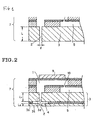
- a liquid discharge device of the present invention is hereinbelow described further concretely with reference to Figs. 1-3 each showing a sectional side elevation of some embodiments of a device for discharging raw material / fuel of the present invention.
- the liquid discharge structure employed in a liquid discharge device shown in Fig. 1 can be produced by molding a compact having a pressure application room provided in a first layer (1), a liquid supply flow path (5) which is provided in a second layer located under the first layer and which communicates with the pressure application room (1) via a minute hole (10) for preventing countercurrent, the communicating hole which connects a nozzle with the liquid supply flow path (5), and the nozzle (2) provided in a third layer which is located under the second layer with employing a ceramic material, for example, a partially stabilized zirconia powder and an appropriate aid such as binder and solvent according to, for example, a method disclosed in Paragraph Numbers 0010-0013 of Japanese Patent Application No. 9-335210.
- a general technique such as punching or cutting may be employed.
- the liquid discharge structure (7) employed in a device for discharging raw material ⁇ fuel shown in Fig. 2 can be produced by molding a compact having a pressure application room provided in the first layer (1), a liquid supply flow path (5) which is provided in the second layer located under the first layer and which communicates with the pressure application room (1) via a minute hole (10) for preventing countercurrent, the communicating hole which connects the liquid supply flow path (5) and a nozzle, and the nozzle (2) provided in the third layer which is located under the second layer and having a small cavity (4) around a discharge port with employing a ceramic material, for example, a partially stabilized zirconia powder and an appropriate aid such as binder and solvent according to, for example, a method disclosed in Paragraph Numbers 0010-0013 of Japanese Patent Application No. 9-335210.
- the nozzle (2) to which a small cavity (4) was provided around a discharge hole must determine a position of a small cavity (4) by adjusting thickness of three layers, i.e., a 3a layer, a 3b layer, and a 3c layer for the purpose of setting the ratio L 1 /L 2 of distance L 1 between the tip of the pressure application room side and the tip of the trap side to distance L 2 between the tip of the trap side and the tip of the discharge hole side in a plane perpendicular to a longitudinal direction of the pressure application room (1) of the above small cavity (4) to be at least 5.
- the size of a small cavity is in the range of 5 ⁇ ( ⁇ 2 /4) to 20 ⁇ ( ⁇ 2 /4) when a nozzle diameter is ⁇ .
- a 3b layer may be formed by the technique of machine work such as punching or a laser processing before laminating in Fig. 2.
- the liquid discharge structure employed in a device for discharging raw material ⁇ fuel shown in Fig. 3 can be produced by molding a compact having a pressure application room provided in the first layer (1), a liquid supply flow path (5) which is provided in the second layer located under the first layer and which communicates with the pressure application room (1) via a minute hole (10) for preventing countercurrent, the communicating hole which connects the liquid supply flow path (5) and a nozzle, and the nozzle (2) provided in the third layer which is located under the second layer and formed of a taper multistage with employing a ceramic material, for example, a partially stabilized zirconia powder and an appropriate aid such as binder and solvent according to, for example, a method disclosed in Paragraph Numbers 0010-0013 of Japanese Patent Application No. 9-335210.
- it is necessary to fix the length L and diameter d so that the nozzle (2) has an aspect ratio of at least 5.
- the nozzle (2) which is formed by a taper of multistage may employ the third layer constituted of the number of steps to be desired.
- a nozzle diameter of each step is made to be the same, or a diameter of a nozzle formed in the upper step is smaller than one formed in the lower step. It is preferable that a section of each nozzle is formed to be smaller in a portion near to a discharge hole than at the side of the pressure application room (1) because a trap effect of an air bubble rises.
- the trapped air bubble can be released securely.
- a device of the present invention is useful as a discharge device upon combustion of fuel required for a stable liquid discharge or various liquid raw material or upon drying processing. That is, a device of the present invention can be suitably employed as a liquid discharge device upon supplying liquid for raw material for reaction or drying of solution containing an aimed product or a discharge device for various liquid fuel such as oil including an oil fan heater or the like.
Landscapes
- Engineering & Computer Science (AREA)
- Chemical & Material Sciences (AREA)
- Combustion & Propulsion (AREA)
- Mechanical Engineering (AREA)
- General Engineering & Computer Science (AREA)
- Nozzles (AREA)
- Degasification And Air Bubble Elimination (AREA)
- Feeding, Discharge, Calcimining, Fusing, And Gas-Generation Devices (AREA)
- Nozzles For Spraying Of Liquid Fuel (AREA)
Applications Claiming Priority (3)
| Application Number | Priority Date | Filing Date | Title |
|---|---|---|---|
| JP18877998 | 1998-07-03 | ||
| JP18877998A JP3352949B2 (ja) | 1998-07-03 | 1998-07-03 | 原料・燃料用吐出装置 |
| PCT/JP1999/003510 WO2000001491A1 (fr) | 1998-07-03 | 1999-06-30 | Dispositif d'evacuation pour materiaux et combustible |
Publications (2)
| Publication Number | Publication Date |
|---|---|
| EP1093857A1 true EP1093857A1 (fr) | 2001-04-25 |
| EP1093857A4 EP1093857A4 (fr) | 2004-12-29 |
Family
ID=16229652
Family Applications (1)
| Application Number | Title | Priority Date | Filing Date |
|---|---|---|---|
| EP99926843A Withdrawn EP1093857A4 (fr) | 1998-07-03 | 1999-06-30 | Dispositif d'evacuation pour materiaux et combustible |
Country Status (4)
| Country | Link |
|---|---|
| US (1) | US6533197B1 (fr) |
| EP (1) | EP1093857A4 (fr) |
| JP (1) | JP3352949B2 (fr) |
| WO (1) | WO2000001491A1 (fr) |
Cited By (6)
| Publication number | Priority date | Publication date | Assignee | Title |
|---|---|---|---|---|
| WO2001097977A1 (fr) * | 2000-06-20 | 2001-12-27 | Ngk Insulators, Ltd. | Dispositif et procede d'ejection de gouttelettes de liquide |
| EP1312797A1 (fr) * | 2001-11-16 | 2003-05-21 | Ngk Insulators, Ltd. | Systeme d'injection de carburant liquide |
| WO2003069153A1 (fr) * | 2002-02-15 | 2003-08-21 | Ngk Insulators, Ltd. | Dispositif d'injection de liquide |
| WO2006053511A1 (fr) * | 2004-11-16 | 2006-05-26 | Webasto Ag | Procede et dispositif pour produire une nebulisation de carburant finement repartie |
| WO2015084508A1 (fr) * | 2013-12-03 | 2015-06-11 | Illinois Tool Works Inc. | Plaque de restriction de fluide d'impression destinée à un ensemble tête d'impression à jet d'encre et procédé |
| US9566607B2 (en) | 2013-03-14 | 2017-02-14 | Illinois Tool Works Inc. | Surface appearance simulation systems and methods |
Families Citing this family (17)
| Publication number | Priority date | Publication date | Assignee | Title |
|---|---|---|---|---|
| US6875402B2 (en) * | 2000-10-16 | 2005-04-05 | Ngk Insulators, Ltd. | Micropipette, dispenser and method for producing biochip |
| US6739520B2 (en) * | 2001-10-02 | 2004-05-25 | Ngk Insulators, Ltd. | Liquid injection apparatus |
| JP2004052619A (ja) * | 2002-07-18 | 2004-02-19 | Ngk Insulators Ltd | 液体噴射装置 |
| US7124963B2 (en) * | 2004-11-05 | 2006-10-24 | Visteon Global Technologies, Inc. | Low pressure fuel injector nozzle |
| US7198207B2 (en) * | 2004-11-05 | 2007-04-03 | Visteon Global Technologies, Inc. | Low pressure fuel injector nozzle |
| US7438241B2 (en) * | 2004-11-05 | 2008-10-21 | Visteon Global Technologies, Inc. | Low pressure fuel injector nozzle |
| US7104475B2 (en) * | 2004-11-05 | 2006-09-12 | Visteon Global Technologies, Inc. | Low pressure fuel injector nozzle |
| US7168637B2 (en) * | 2004-11-05 | 2007-01-30 | Visteon Global Technologies, Inc. | Low pressure fuel injector nozzle |
| US7051957B1 (en) * | 2004-11-05 | 2006-05-30 | Visteon Global Technologies, Inc. | Low pressure fuel injector nozzle |
| US7137577B2 (en) * | 2004-11-05 | 2006-11-21 | Visteon Global Technologies, Inc. | Low pressure fuel injector nozzle |
| US7185831B2 (en) * | 2004-11-05 | 2007-03-06 | Ford Motor Company | Low pressure fuel injector nozzle |
| TWI290485B (en) * | 2005-12-30 | 2007-12-01 | Ind Tech Res Inst | Spraying device |
| EP2070429A1 (fr) * | 2007-12-13 | 2009-06-17 | Cognis IP Management GmbH | Stabilisation oxydative de stérols et esters de stérols |
| JP5343869B2 (ja) * | 2010-01-15 | 2013-11-13 | セイコーエプソン株式会社 | ゲル製造装置 |
| KR101890755B1 (ko) * | 2011-11-25 | 2018-08-23 | 삼성전자 주식회사 | 잉크젯 프린팅 장치 및 노즐 형성 방법 |
| US9193163B2 (en) * | 2013-02-01 | 2015-11-24 | Canon Kabushiki Kaisha | Liquid discharge apparatus and manufacturing method thereof |
| CN113772772B (zh) * | 2021-08-31 | 2023-07-18 | 国网冀北电力有限公司电力科学研究院 | 溶解氧去除装置、换流阀内冷水系统及其溶解氧去除方法 |
Family Cites Families (15)
| Publication number | Priority date | Publication date | Assignee | Title |
|---|---|---|---|---|
| US2201080A (en) * | 1938-12-24 | 1940-05-14 | Thomas Oldt Gutelius | Pressure cleaning apparatus |
| JPS58108158A (ja) * | 1981-12-23 | 1983-06-28 | Ricoh Co Ltd | インクジエツト記録装置 |
| US4734227A (en) * | 1983-09-01 | 1988-03-29 | Battelle Memorial Institute | Method of making supercritical fluid molecular spray films, powder and fibers |
| US4695854A (en) | 1986-07-30 | 1987-09-22 | Pitney Bowes Inc. | External manifold for ink jet array |
| US5155498A (en) * | 1990-07-16 | 1992-10-13 | Tektronix, Inc. | Method of operating an ink jet to reduce print quality degradation resulting from rectified diffusion |
| DE69111936T2 (de) * | 1990-08-16 | 1996-04-11 | Hewlett Packard Co | Photo-ablatierte Bauteile für Farbstrahldruckkopf. |
| ES2253174T3 (es) * | 1991-03-01 | 2006-06-01 | THE PROCTER & GAMBLE COMPANY | Pulverizacion de liquidos. |
| JPH05177834A (ja) * | 1991-06-04 | 1993-07-20 | Seiko Epson Corp | インクジェット記録ヘッド |
| JP3144948B2 (ja) | 1992-05-27 | 2001-03-12 | 日本碍子株式会社 | インクジェットプリントヘッド |
| JPH0699105A (ja) | 1992-09-24 | 1994-04-12 | Matsushita Electric Ind Co Ltd | 霧化ノズル |
| JPH08274014A (ja) | 1995-03-29 | 1996-10-18 | Tokyo Ohka Kogyo Co Ltd | 塗布ノズル、この塗布ノズルを用いた塗布方法及びこの塗布ノズルを組み込んだ塗布装置 |
| US5969733A (en) * | 1996-10-21 | 1999-10-19 | Jemtex Ink Jet Printing Ltd. | Apparatus and method for multi-jet generation of high viscosity fluid and channel construction particularly useful therein |
| JP3809706B2 (ja) * | 1997-06-16 | 2006-08-16 | ブラザー工業株式会社 | インクジェットプリンタヘッド並びにインクジェットプリンタヘッドの加工及び検査方法 |
| JP3835942B2 (ja) | 1997-12-05 | 2006-10-18 | 日本碍子株式会社 | 粉末の製造方法 |
| US6126339A (en) * | 1998-09-04 | 2000-10-03 | Konica Corporation | Automatic processor for silver halide photosensitive photographic material |
-
1998
- 1998-07-03 JP JP18877998A patent/JP3352949B2/ja not_active Expired - Fee Related
-
1999
- 1999-06-30 WO PCT/JP1999/003510 patent/WO2000001491A1/fr not_active Ceased
- 1999-06-30 US US09/720,351 patent/US6533197B1/en not_active Expired - Fee Related
- 1999-06-30 EP EP99926843A patent/EP1093857A4/fr not_active Withdrawn
Cited By (8)
| Publication number | Priority date | Publication date | Assignee | Title |
|---|---|---|---|---|
| WO2001097977A1 (fr) * | 2000-06-20 | 2001-12-27 | Ngk Insulators, Ltd. | Dispositif et procede d'ejection de gouttelettes de liquide |
| US6752326B2 (en) | 2000-06-20 | 2004-06-22 | Ngk Insulators, Ltd. | Liquid droplet ejection apparatus and liquid droplet ejecting method |
| EP1312797A1 (fr) * | 2001-11-16 | 2003-05-21 | Ngk Insulators, Ltd. | Systeme d'injection de carburant liquide |
| US6845759B2 (en) | 2001-11-16 | 2005-01-25 | Ngk Insulators, Ltd. | Liquid fuel injection system |
| WO2003069153A1 (fr) * | 2002-02-15 | 2003-08-21 | Ngk Insulators, Ltd. | Dispositif d'injection de liquide |
| WO2006053511A1 (fr) * | 2004-11-16 | 2006-05-26 | Webasto Ag | Procede et dispositif pour produire une nebulisation de carburant finement repartie |
| US9566607B2 (en) | 2013-03-14 | 2017-02-14 | Illinois Tool Works Inc. | Surface appearance simulation systems and methods |
| WO2015084508A1 (fr) * | 2013-12-03 | 2015-06-11 | Illinois Tool Works Inc. | Plaque de restriction de fluide d'impression destinée à un ensemble tête d'impression à jet d'encre et procédé |
Also Published As
| Publication number | Publication date |
|---|---|
| EP1093857A4 (fr) | 2004-12-29 |
| WO2000001491A1 (fr) | 2000-01-13 |
| JP2000015144A (ja) | 2000-01-18 |
| JP3352949B2 (ja) | 2002-12-03 |
| US6533197B1 (en) | 2003-03-18 |
Similar Documents
| Publication | Publication Date | Title |
|---|---|---|
| US6533197B1 (en) | Device for discharging raw material-fuel | |
| EP1293257A1 (fr) | Dispositif et procede d'ejection de gouttelettes de liquide | |
| EP3173235B1 (fr) | Dispositif d'éjection de fluide avec canal de restriction et son procédé de fabrication | |
| US20100078505A1 (en) | Laminated piezolectric element, jetting device provided with the laminated piezoelectric element and fuel jetting system | |
| DE69936122T2 (de) | Elektrostatischer betätiger, verfahren zu seiner herstellung und diesen verwendende flüssigkeitsspritzvorrichtung | |
| WO1993001404A1 (fr) | Ejecteur de liquide a ultrasons | |
| US7317276B2 (en) | Liquid delivering device | |
| JP7123398B2 (ja) | 流体エジェクタ | |
| US6485275B1 (en) | Device for discharging raw material-fuel | |
| JP2008503374A (ja) | インクジェット・プリンティングモジュール | |
| US6997547B2 (en) | Piezoelectric element, piezoelectric actuator and liquid jetting head incorporating the same | |
| US20030112319A1 (en) | Low voltage ink jet printing module | |
| US6257482B1 (en) | Jet solder feeding device and soldering method | |
| US7374628B2 (en) | Method for manufacturing a cell-driving-type micro pump member | |
| JP6883876B2 (ja) | 電子部品接着用ノズル | |
| EP4108462B1 (fr) | Microfluidique amélioré dispositif pour la pulvérisation de très petites gouttes de liquides | |
| CN115501987A (zh) | 用于喷射非常小的液滴的改进的微流体设备 | |
| US7158159B2 (en) | Micro-machined nozzles | |
| US11192367B2 (en) | Piezoelectric device, liquid discharging head, and liquid discharging apparatus | |
| CN120569263A (zh) | 液滴喷出装置 | |
| JP2002086021A (ja) | 液滴吐出装置 | |
| CN117981926A (zh) | 一种供液组件及雾化装置 | |
| JP2002043351A (ja) | 半田バンプ形成装置、半田バンプ形成方法、および該半田バンプ形成装置による半導体の製造方法 | |
| CN118082378A (zh) | 液体喷出头以及液体喷出装置 | |
| JP2000279856A (ja) | 液滴吐出装置 |
Legal Events
| Date | Code | Title | Description |
|---|---|---|---|
| PUAI | Public reference made under article 153(3) epc to a published international application that has entered the european phase |
Free format text: ORIGINAL CODE: 0009012 |
|
| 17P | Request for examination filed |
Effective date: 20010118 |
|
| AK | Designated contracting states |
Kind code of ref document: A1 Designated state(s): DE FR GB IT |
|
| A4 | Supplementary search report drawn up and despatched |
Effective date: 20041116 |
|
| RIC1 | Information provided on ipc code assigned before grant |
Ipc: 7F 23D 11/34 B Ipc: 7B 05B 17/06 B Ipc: 7B 05B 1/00 A |
|
| STAA | Information on the status of an ep patent application or granted ep patent |
Free format text: STATUS: THE APPLICATION HAS BEEN WITHDRAWN |
|
| 18W | Application withdrawn |
Effective date: 20050111 |