EP1093887B1 - Tête de dosage, en particulier pour outil de scellement entraîné par combustion - Google Patents
Tête de dosage, en particulier pour outil de scellement entraîné par combustionInfo
- Publication number
- EP1093887B1 EP1093887B1 EP00810885A EP00810885A EP1093887B1 EP 1093887 B1 EP1093887 B1 EP 1093887B1 EP 00810885 A EP00810885 A EP 00810885A EP 00810885 A EP00810885 A EP 00810885A EP 1093887 B1 EP1093887 B1 EP 1093887B1
- Authority
- EP
- European Patent Office
- Prior art keywords
- metering
- outlets
- head
- valves
- chambers
- Prior art date
- Legal status (The legal status is an assumption and is not a legal conclusion. Google has not performed a legal analysis and makes no representation as to the accuracy of the status listed.)
- Expired - Lifetime
Links
- 238000002485 combustion reaction Methods 0.000 title claims description 37
- 239000007788 liquid Substances 0.000 claims description 23
- 239000007789 gas Substances 0.000 description 33
- 239000002737 fuel gas Substances 0.000 description 32
- 239000000203 mixture Substances 0.000 description 13
- 239000012530 fluid Substances 0.000 description 7
- 238000004891 communication Methods 0.000 description 6
- 230000006835 compression Effects 0.000 description 2
- 238000007906 compression Methods 0.000 description 2
- 238000010276 construction Methods 0.000 description 2
- 238000002156 mixing Methods 0.000 description 2
- 239000011324 bead Substances 0.000 description 1
- 239000001273 butane Substances 0.000 description 1
- 238000001816 cooling Methods 0.000 description 1
- 230000001419 dependent effect Effects 0.000 description 1
- 238000000034 method Methods 0.000 description 1
- 239000003595 mist Substances 0.000 description 1
- IJDNQMDRQITEOD-UHFFFAOYSA-N n-butane Chemical compound CCCC IJDNQMDRQITEOD-UHFFFAOYSA-N 0.000 description 1
- OFBQJSOFQDEBGM-UHFFFAOYSA-N n-pentane Natural products CCCCC OFBQJSOFQDEBGM-UHFFFAOYSA-N 0.000 description 1
- 230000002093 peripheral effect Effects 0.000 description 1
- 238000007789 sealing Methods 0.000 description 1
- 238000009834 vaporization Methods 0.000 description 1
- 230000008016 vaporization Effects 0.000 description 1
Images


Classifications
-
- B—PERFORMING OPERATIONS; TRANSPORTING
- B25—HAND TOOLS; PORTABLE POWER-DRIVEN TOOLS; MANIPULATORS
- B25C—HAND-HELD NAILING OR STAPLING TOOLS; MANUALLY OPERATED PORTABLE STAPLING TOOLS
- B25C1/00—Hand-held nailing tools; Nail feeding devices
- B25C1/08—Hand-held nailing tools; Nail feeding devices operated by combustion pressure
-
- F—MECHANICAL ENGINEERING; LIGHTING; HEATING; WEAPONS; BLASTING
- F17—STORING OR DISTRIBUTING GASES OR LIQUIDS
- F17C—VESSELS FOR CONTAINING OR STORING COMPRESSED, LIQUEFIED OR SOLIDIFIED GASES; FIXED-CAPACITY GAS-HOLDERS; FILLING VESSELS WITH, OR DISCHARGING FROM VESSELS, COMPRESSED, LIQUEFIED, OR SOLIDIFIED GASES
- F17C13/00—Details of vessels or of the filling or discharging of vessels
- F17C13/04—Arrangement or mounting of valves
-
- F—MECHANICAL ENGINEERING; LIGHTING; HEATING; WEAPONS; BLASTING
- F17—STORING OR DISTRIBUTING GASES OR LIQUIDS
- F17C—VESSELS FOR CONTAINING OR STORING COMPRESSED, LIQUEFIED OR SOLIDIFIED GASES; FIXED-CAPACITY GAS-HOLDERS; FILLING VESSELS WITH, OR DISCHARGING FROM VESSELS, COMPRESSED, LIQUEFIED, OR SOLIDIFIED GASES
- F17C2205/00—Vessel construction, in particular mounting arrangements, attachments or identifications means
- F17C2205/03—Fluid connections, filters, valves, closure means or other attachments
- F17C2205/0302—Fittings, valves, filters, or components in connection with the gas storage device
- F17C2205/0382—Constructional details of valves, regulators
Definitions
- the invention relates to a dosing according to claim 1, which is particularly suitable for use in combustion-powered setting tools, with the help of fasteners can be shot into objects.
- an air / fuel gas mixture provided a drive energy and transmitted via a piston to the fastener, which may for example be in the form of a nail, a bolt, or the like.
- the air / fuel gas mixture is possibly in different mixing ratios in all sub-combustion chambers of a subdivided into several combustion chambers combustion chamber.
- the partial combustion chambers are connected to each other by means of a plurality of passage openings.
- the combustion is started in a first rear partial combustion chamber, and it starts to spread a flame front at a relatively slow speed in this partial combustion chamber. It pushes unburned air / fuel gas mixture before it, which passes through the passage openings in the next part of the combustion chamber, etc., and here produces turbulence and precompression.
- the flames When the flame front reaches the passage openings to the next partial combustion chamber, the flames, due to the small cross sections of the passage openings, accelerate as flame jets into the next partial combustion chamber and generate further turbulence here.
- the mixed, turbulent air / fuel gas mixture in this partial combustion chamber is then ignited over the entire surface of the flame jets. It burns at a high speed, which leads to a strong increase in the efficiency of the combustion, since the cooling losses remain small. In this way, a partial combustion chamber (or main chamber) limiting piston is driven, the drive energy is transmitted to the fastener.
- a combustion-powered setting tool for fastening elements an air / fuel gas mixture is sucked into the partial combustion chambers by clamping the partial combustion chambers.
- the air / fuel gas mixture can thus not be set individually for the individual partial combustion chambers. This precludes optimal operation of the device. In addition, it is not ensured that an ignitable air / -brenngasgemisch is obtained in each of the partial combustion chamber at all.
- US 4,913,331 describes a setting device for fasteners with multiple combustion chambers.
- a filling cylinder is fixed, in which a piston moves, which is acted upon by a spring.
- a fuel gas chamber is formed, which is filled for example with butane.
- a measuring cylinder in which a metering valve is movably arranged.
- a measuring chamber is connected via a first channel to the fuel gas chamber and in another position of the metering valve to a second channel.
- the second channel opens into a mixture forming chamber, which is connected via a nozzle to a combustion chamber.
- the nozzle is equipped with two output channels.
- the invention has for its object to provide a dosing, with the individual dosing of different rooms with fuel gas is possible.
- a dosing head for the metered output of a liquid fuel gas in different combustion chambers of a working device, in particular a fastener setting device, has an inlet for receiving the liquid fuel gas and at least two outputs and further includes at least one with the input and the Outputs connected metering valve.
- individually metered fuel gas can be dispensed in liquid form via the respective outlets, so that the individual and ignitable gas mixtures in the respective combustion chambers can be set separately in accordance with desired operating conditions of a combustion-powered setting device in order to increase the reliability and efficiency of the device improve. It is thus obtained under all conditions in all partial combustion chambers an ignitable gas mixture, the z.
- an air-fuel gas mixture, an oxygen-fuel gas mixture or any other suitable combustible gas mixture may be.
- a metering valve and a plurality of outputs are present, then an individual metering per output can take place in that the outputs have, for example, different output cross sections.
- the dosing head contains two or more metering valves, which are connected to its input in common and in each case separately to one of its two or more outlets, then the individual metering per output channel can be set by selecting the metering volume of the respective metering valves, that is to say by selecting metering valves with different large dosing chambers.
- the size of the output openings of the outputs could also be set here, if this was still necessary.
- the outlets may preferably be formed as nozzles for dispensing a mist of fuel gas for metering so that better vaporization of the liquid fuel gas is possible, and thus better mixing for setting a desired gas mixture of e.g. Air and fuel gas.
- a desired gas mixture e.g. Air and fuel gas.
- the inlets of the dosing of all dosing valves can be permanently connected to its input.
- its input may be surrounded by resilient lugs in order to clamp the dosing head onto a bottle in which liquid fuel gas is contained.
- the lugs engage behind a corresponding peripheral flange at the outlet of the gas cylinder.
- the input of the dosing acts on the outlet valve of the gas cylinder and opens it, so that in this way all dosing located in the dosing are constantly filled when the inlets of the dosing are open.
- the metering valves can be arranged so that a metering valve longitudinal axis is perpendicular to a longitudinal axis of the outputs.
- inlets and outlets of metering chambers of the metering valves can thereby be opened and closed, So be switched that the input of the dosing head is moved relative to a Dosierkopfgephaseuse perpendicular to the direction of the longitudinal axes of the outputs. This can be done for example by lifting the gas cylinder, ie by moving the gas cylinder on the dosing to or away from it. Such movement of the gas cylinder may be in accordance with the operation of the setting device whose combustion chambers are to be filled with fuel gas by means of the dosing head.
- the metering valves may be arranged in the dosing head so that a metering valve longitudinal axis runs parallel to a longitudinal axis of the outputs.
- inlets and outlets of metering chambers of the metering valves can thereby be opened and closed, that is switched, that the metering valves are moved relative to the outputs of the metering in the direction of the longitudinal axes of the outputs.
- the outputs of the dosing head are fixedly inserted into a combustion chamber wall, and only that part of the dosing head which carries the dosing valves is moved towards or away from the outputs, also in accordance with the operations of the setting device, whose combustion chambers are to be filled with the aid of the dosing with liquid fuel gas.
- the portion of the dosing head carrying the dosing valves and the gas cylinder, which is in fluid contact with the inlet of the dosing head, are firmly connected to one another.
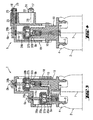
- a dosing head 1 is fixedly mounted on a gas cylinder 2, in which a liquid fuel gas is located.
- the dosing head 1 has for this purpose in its lower region resiliently formed and downwardly projecting hooks 3, which engage behind a circumferential bead 4 on the upper end side of the gas cylinder 2 from the inside.
- a metering valve 5 Within the dosing head 1 is a metering valve 5, whose longitudinal axis 6 is aligned with the longitudinal axis 7 of the gas cylinder 2.
- An unillustrated valve chamber of the metering valve 5 is connected on the input side to a hollow pipe 8 which projects from the bottom 9 of the metering head 1. If the dosing head 1 is placed on the gas cylinder 2, the hollow socket 8 engages in the outlet valve of the gas cylinder 2 and opens it. Liquefied gas is thus passed from the gas cylinder 2 and through the hollow pipe 8 into a channel 10 of the metering valve and finally reaches its metering chamber.
- the dosing of the metering valve 5 is thus constantly filled via the inlet with liquid fuel gas when the dosing head 1 is mounted on the gas cylinder 2 and is not operated.
- an outlet of the metering chamber of the metering valve 5 is initially closed and is opened only when needed, in which case the inlet to the metering chamber is briefly closed. This will be done later.
- the outlet of the metering chamber is connected via an outlet channel 11 of the metering valve 5 in fluid communication with an annular channel 12, via a connecting channel 13. From the annular channel 12 go from two transverse channels 14 and 15, each in a Ausspritzdüse 16 and 17 open.
- the annular channel 12, the connecting channel 13 and the transverse channels 14 and 15 are located in a cap portion 18 of the dosing head 1, wherein the cap member 18 receives the metering valve 5 in its lower portion and a bottom portion 19 of the metering valve 1, relative to the cap member 18 in the direction the metering valve longitudinal axis 6 is displaceable and the metering valve 5 carries.
- the already mentioned hook 3 and the hollow pipe 8 are for example integrally attached.
- the output channel 11 of the metering valve 5 is first inserted in the direction of the metering valve longitudinal axis 6 in the correspondingly extending part of the connecting channel 13. If an outer flange 20 of the metering valve 5 is raised by lifting the gas cylinder 2 and inserting the bottom part 19 into the cap part 18, the inlet to the metering chamber of the metering valve 5 is first closed and then the outlet of the metering chamber of the metering valve 5 is opened so that the metered volume at liquid fuel gas to the ejection nozzles 16 and 17 passes.
- the ejection nozzles 16 and 17 are located in cylindrical members 21 and 22 which are connected to the cap member 18.
- These cylindrical members 21 and 22 have outer sealing rings 23 and 24 to be sealingly inserted into corresponding recesses in the combustion chamber wall of a setting tool.
- the cap member 18 is fixed or immovably connected to the combustion chamber wall.
- Longitudinal axes 25 and 26 of the ejection nozzles 16 and 17 (outputs of the dosing head 1) are perpendicular to the longitudinal axis 6 of the metering valve 5. If the gas cylinder 2 is relieved again, it takes the bottom part 19 with it and moves it slightly out of the cap part 18 downwards out. This leads first to the closure of the outlet of the metering chamber of the metering valve 5 and then to the opening of its inlet, so that the metering chamber is filled again with liquid fuel gas.
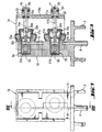
- Figures 3 and 4 show a second embodiment of a dosing head according to the invention 1.
- the same parts as in the first embodiment of Figures 1 and 2 are provided with the same reference numerals and will not be described again.
- the dosing head 1 has two metering valves 5a and 5b whose metering valve longitudinal axes 6a and 6b are spaced apart and parallel to the longitudinal axis 7 of the gas cylinder 2. If the valve head 1 is seated firmly on the gas cylinder 2 and the bottom part 19 is not displaced relative to the cap part 18, valve chambers 27a, 27b of both metering valves 5a, 5b are constantly and simultaneously filled with liquid fuel gas, via the hollow pipe 8 and a suitable one Channel 10, which runs in the interior of the bottom part 19. This channel 10 is in fluid communication with the hollow pipe 8.
- the inlets 30a, 30b to the valve chambers 27a, 27b are now open, as can be seen in particular Figure 3.
- Outlets 28a and 28b of the valve chambers 27a, 27b are still closed in the position according to FIG. They are in turn via output channels 11a, 11b with transverse channels 29a, 29b in fluid communication, which in turn open into the nozzles 16 and 17.
- the output channels 11a, 11b are supported on the edge region of the transverse channels 29a, 29b. If the gas cylinder 2 is pressed in the direction of the cap part 18 when the cap part 18 is stationary, the bottom part 19 is partially retracted into the cap part 18. Initially, the inlets 30a, 30b of the metering chambers 27a, 27b are closed and their outlets 28a, 28b are opened. This allows the metered liquid to flow to the nozzles 16 and 17.
- FIGS. 5 to 8 A third embodiment of a dosing head 1 according to the invention is shown in FIGS. 5 to 8. This is a dosing head 1 with two metering valves 5a, 5b, whose metering valve longitudinal axes 6a, 6b are perpendicular to the longitudinal axis 7 of the gas cylinder 2.
- the same parts as in Figures 1 and 2 or 3 and 4 are again provided with the same reference numerals and will not be described again.
- the metering chambers 27a, 27b of the metering valves 5a, 5b are in fluid communication with the hollow stub 8 via a channel 10, so that they are filled with liquid fuel gas when the outlets 28a, 28b are not within the Dosing chambers 27a, 27b come to rest, so are virtually closed. In this case, no liquid fuel gas reaches the nozzles 16, 17.
- the output passages 11a, 11b in fluid communication with the outlets 28a, 28b terminate in a rear face sealingly into a front plate 18a of the cap member 18.
- the exit passages 11a, 11b are in fluid communication with the nozzles 16 and 17.
- the cylindrical members 21 and 22 having the nozzles 16 and 17 are integrally connected to the front plate 18a and have inner channels 16a, 17a extending from the nozzles 16, 17 to the output ports 11a, 11b.
- the connection between the front plate 18a and the output channels 11a, 11b is at least liquid-tight in the edge region of the output channels 11a, 11b.
- the front plate 18a is perpendicular to the longitudinal axes 6a, 6b of the metering valves 5a, 5b and is inserted via their cylindrical components 21, 22 fixed in corresponding openings of a combustion chamber wall.
- the bottom part 19, with which the gas cylinder 2 is fixedly connected are displaced in the direction of the front plate 18a, in accordance with the working cycle of the setting device whose combustion chambers are to be filled via the nozzles 16 and 17 with liquid fuel gas.
- a drive mechanism controlled by the setting device can act on the bottom part 19 in the longitudinal direction of the axles 6a, 6b or 25, 26.
- the bottom part 19 remains unencumbered, ie unshifted, liquid fuel gas from the gas cylinder 2 is supplied to the metering chambers 27a, 27b together, via the hollow pipe 8 and the adjoining channel pipe 10. It connects the inner channel of the hollow pipe 8 with both metering chambers 27a , 27b.
- the inlets 30a, 30b of these metering chambers are now open, wherein they can be seen in FIG. They bear the reference numerals 30a, 30b.
- the outlets 28a, 28b are outside the metering chambers 27a, 27b and are therefore closed.
- Springs 31a, 31b which are supported on the bottom part 19, constantly push a valve tappet 32a, 32b into the position in which the inlets 30a, 30b are opened.
- the output channels 11a, 11b seated on the valve tappets 32a, 32b are supported on the front panel 18a.
- the valve chamber housing 33 a, 33 b connected to the bottom part 19 a is entrained accordingly, so that it closes the inlets 30 a, 30 b on the side to the bottom and toward the Nozzles 16, 17 pass over the inlets 28a, 28b, so that they come to lie within the valve chambers 27a, 27b.
- Dosed liquid gas in the metering chambers 27a, 27b can then pass through the outlets 28a, 28b and the channels 11a, 11b to the nozzles 16, 17.
- the valve chamber housing 33a, 33b are moved back and the outlets closed.
- the springs 31a, 31b hold the valve tappets 32a, 32b so that the inlets 30a, 30b open again.
- FIG. 9 shows an axial section through a metering valve used in the invention.
- the valve lifter 32a carries a cylinder 37 having the exit passage 11a and a lateral transverse passage 28a which may be referred to as a valve outlet.
- a valve chamber housing 33a forms the valve chamber 27a and has an elastic seal 34 at the end facing the valve lifter 32a.
- a flange 20a holds the valve chamber housing 33a relative to the bottom part 19.
- the free end of the outlet passage 11a is in contact with the front plate 18a shown in FIG the cap portion 18.
- the output channel 11a with the help of the already mentioned compression spring 31a on the valve stem 32a pressed against the front panel 18a.
- the compression spring 31a is supported on the bottom of the bottom part 19.
- FIG. 9 shows a position of the valve chamber housing 33a relative to the outlet channel 11a, in which the transverse channel 28a comes to lie within the valve chamber 27a.
- the outlet of the metering valve is thus open, so that in the valve chamber 27 a befindliches liquid fuel gas can be output via the channels 28 a, 11 a. If the bottom part 19 is relieved, it pulls the flange 20a relative to the valve stem 32a and the output channel 11a to the rear, so that the flange 20a passes over the transverse channel 28ain Figure 9 to the left. The outlet of the metering valve is thus closed.
- the elastic portion 34 of the valve chamber housing 33a is moved over a beveled trailing edge 35 of the cylinder 37, so that now there is a gap between this edge 35 and the opposite elastic member 34 so that valve chamber inlets 30a are present through in the direction of arrow liquid fuel gas can flow into the valve chamber 27 a.
- the retracted position of the flange 20a is limited by a stop 36 on the outside of the cylinder 37.
Landscapes
- Engineering & Computer Science (AREA)
- Chemical & Material Sciences (AREA)
- Combustion & Propulsion (AREA)
- Mechanical Engineering (AREA)
- Portable Nailing Machines And Staplers (AREA)
- Feeding And Controlling Fuel (AREA)
- Containers And Packaging Bodies Having A Special Means To Remove Contents (AREA)
Claims (12)
- Tête de dosage (1) pour la fourniture dosée d'un gaz combustible liquide à différentes chambres de combustion d'un outil de travail, en particulier d'un outil de scellement d'éléments de fixation, avec une entrée (8) pour recevoir le gaz combustible liquide et avec au moins deux sorties (16, 17) ainsi qu'avec au moins une soupape de dosage (5 ; 5a, 5b) reliée à l'entrée (8) et aux sorties (16, 17), caractérisée en ce que les sorties (16, 17) comportent chacune un canal de sortie (11a, 11b ; 14, 15) qui peut être relié à une des différentes chambres de combustion.
- Tête de dosage pour la fourniture dosée d'un gaz combustible liquide à différentes chambres de combustion d'un outil de travail, en particulier d'un outil de scellement d'éléments de fixation, avec une entrée (8) pour recevoir le gaz combustible liquide et avec au moins deux sorties (16, 17), caractérisée en ce qu'elle renferme deux soupapes de dosage ou plus (5a, 5b) qui sont reliées conjointement à l'entrée (8) et séparément à une de ses deux sorties ou plus (16, 17), et en ce que les sorties (16, 17) comportent chacune un canal de sortie (11a, 11b, 14, 15) qui peut être relié à une des différentes chambres de combustion.
- Tête de dosage (1) selon la revendication 1 ou 2, caractérisée en ce qu'un axe longitudinal de soupape de dosage (6 ; 6a, 6b) s'étend au moins sensiblement perpendiculairement à un axe longitudinal des sorties (16, 17).
- Tête de dosage (1) selon la revendication 1 ou 2, caractérisée en ce qu'un axe longitudinal de soupape de dosage (6a, 6b) s'étend au moins sensiblement parallèlement à un axe longitudinal des sorties (16, 17).
- Tête de dosage (1) selon une des revendications 1 à 4, caractérisée en ce que les sorties sont conformées en buses (16, 17).
- Tête de dosage (1) selon une des revendications 1 à 5, caractérisée en ce que les sorties (16, 17) sont de dimensions différentes.
- Tête de dosage (1) selon la revendication 2, caractérisée en ce que les soupapes de dosage (5a, 5b) comportent des chambres de dosage (27a, 27b) de dimensions différentes.
- Tête de dosage (1) selon une des revendications 2 à 7, caractérisée en ce que des orifices d'admission (30a, 30b) de chambres de dosage (27a, 27b) des soupapes de dosage (5 ; 5a, 5b) sont en communication permanente avec son entrée (8).
- Tête de dosage (1) selon une des revendications 2, 3 et 5 à 8, caractérisée en ce que les orifices d'admission (30a, 30b) et les orifices d'échappement (28a, 28b) des chambres de dosage (27a, 27b) des soupapes de dosage (5a, 5b) sont commutables en déplaçant-une partie de fond de tête de dosage (19) comportant son entrée (8) par rapport à un boîtier de tête de dosage (18) comportant les sorties (16, 17), perpendiculairement à la direction des axes longitudinaux (25, 26) des sorties (16, 17).
- Tête de dosage (1) selon une des revendications 2, 4 et 8, caractérisée en ce que les orifices d'admission (30a, 30b) et les orifices d'échappement (16, 17) des chambres de dosage (27a, 27b) des soupapes de dosage (5a, 5b) sont commutables en déplaçant les soupapes de dosage (5a, 5b) par rapport à ses sorties (16, 17) dans la direction des axes longitudinaux (25, 26) des sorties (16, 17).
- Tête de dosage selon la revendication 10, caractérisée en ce qu'elle comporte une plaque frontale fixable (18a) pourvue des sorties (16, 17) et une partie de fond de tête de dosage (19) qui peut se rapprocher de la plaque frontale (18) et s'en éloigner et qui reçoit les soupapes de dosage (5a, 5b).
- Tête de dosage (1) selon une des revendications 1 à 11, caractérisée en ce que son entrée (8) est entourée par des appendices élastiques (3).
Applications Claiming Priority (2)
| Application Number | Priority Date | Filing Date | Title |
|---|---|---|---|
| DE19950350 | 1999-10-19 | ||
| DE19950350A DE19950350C2 (de) | 1999-10-19 | 1999-10-19 | Dosierkopf, insbesondere für brennkraftbetriebene Setzgeräte |
Publications (3)
| Publication Number | Publication Date |
|---|---|
| EP1093887A2 EP1093887A2 (fr) | 2001-04-25 |
| EP1093887A3 EP1093887A3 (fr) | 2004-10-06 |
| EP1093887B1 true EP1093887B1 (fr) | 2006-08-16 |
Family
ID=7926168
Family Applications (1)
| Application Number | Title | Priority Date | Filing Date |
|---|---|---|---|
| EP00810885A Expired - Lifetime EP1093887B1 (fr) | 1999-10-19 | 2000-09-26 | Tête de dosage, en particulier pour outil de scellement entraîné par combustion |
Country Status (6)
| Country | Link |
|---|---|
| US (1) | US6419168B1 (fr) |
| EP (1) | EP1093887B1 (fr) |
| JP (1) | JP4729163B2 (fr) |
| KR (1) | KR20010049981A (fr) |
| DE (2) | DE19950350C2 (fr) |
| ES (1) | ES2270802T3 (fr) |
Families Citing this family (24)
| Publication number | Priority date | Publication date | Assignee | Title |
|---|---|---|---|---|
| US6796478B2 (en) * | 2000-10-12 | 2004-09-28 | Illinois Tool Works Inc. | Fuel cell adapter system for combustion tools |
| FR2827528B1 (fr) * | 2001-07-20 | 2004-07-09 | Oreal | Tete de distribution comportant deux buses |
| FR2832344B1 (fr) * | 2001-11-21 | 2004-01-23 | Spit Soc Prospect Inv Techn | Appareil de fixation a piston propulse par gaz comprime |
| DE10158626B4 (de) * | 2001-11-29 | 2006-07-13 | Hilti Ag | Tragbares, brennkraftbetriebenes Arbeitsgerät und Verfahren zu seiner Betriebssteuerung |
| US6786378B2 (en) | 2002-01-09 | 2004-09-07 | Illinois Tool Works Inc. | Fastener tool having auxiliary fuel cell metering valve stem seal adaptor |
| DE10306353A1 (de) * | 2003-02-15 | 2004-08-26 | Hilti Ag | Setzgerätesystem und brennkraftbetriebenes Setzgerät sowie Dosierkopf für brennkraftbetriebene Setzgeräte |
| US6938810B2 (en) | 2003-04-15 | 2005-09-06 | Illinois Tool Works Inc. | Fuel cell adapter system for combustion tools |
| US6892524B1 (en) * | 2003-11-03 | 2005-05-17 | Illinois Tool Works Inc. | Latching mechanism for combustion chamber plate of a fastener driving tool |
| US6966478B2 (en) * | 2003-11-03 | 2005-11-22 | Illinois Tool Works Inc | Combustion apparatus having collapsible volume |
| US7571841B2 (en) * | 2004-04-19 | 2009-08-11 | Illinois Tool Works, Inc. | Interchangeable adapter for in-can and on-can fuel cells |
| US7392922B2 (en) * | 2004-04-19 | 2008-07-01 | Illinois Tool Works Inc. | In-can fuel cell metering valve |
| JP5586157B2 (ja) * | 2008-02-25 | 2014-09-10 | フマキラー株式会社 | 害虫駆除用エアゾール |
| JP5104536B2 (ja) * | 2008-05-16 | 2012-12-19 | マックス株式会社 | 燃料充填容器及びガス燃焼式打込み工具 |
| PT2508446T (pt) * | 2009-12-01 | 2016-08-22 | Toyo Aerosol Ind Co | Dispositivo de aerossol para alocação de uma pluralidade de fluidos |
| FR2965799B1 (fr) * | 2010-10-06 | 2012-10-05 | Lindal France Sas | Diffuseur pour valve multivoie |
| PT2647587T (pt) * | 2010-12-02 | 2016-12-20 | Toyo Aerosol Ind Co | Dispositivo de aerossol de distribuição de múltiplos líquidos |
| DE102010063177A1 (de) * | 2010-12-15 | 2012-06-21 | Hilti Aktiengesellschaft | Bolzensetzgerät und Verfahren zum Betreiben eines Bolzensetzgerätes |
| KR20150081254A (ko) * | 2012-11-07 | 2015-07-13 | 이지-에프엘오 인젝션 시스템즈 인코퍼레이티드 | 유체 주입 시스템 |
| TWM461519U (zh) | 2013-04-29 | 2013-09-11 | Basso Ind Corp | 計量閥 |
| AU2014265061A1 (en) * | 2014-11-20 | 2016-06-09 | Liu, Darren Yu Jen | Dual-purpose gas fuel can gas outlet structure |
| US10166666B2 (en) * | 2015-11-25 | 2019-01-01 | Illinois Tool Works Inc. | Adapter for combustion tool fuel cells |
| US10557738B2 (en) | 2017-09-11 | 2020-02-11 | Black & Decker Inc. | External fuel metering valve with shuttle mechanism |
| EP4228981A4 (fr) * | 2020-11-12 | 2024-09-25 | Precision Valve Corporation | Système de distribution par pulvérisation |
| US11623799B2 (en) * | 2021-01-27 | 2023-04-11 | Theodros Shawl | Contamination free liquid-spray dispensing apparatus and method of use |
Family Cites Families (15)
| Publication number | Priority date | Publication date | Assignee | Title |
|---|---|---|---|---|
| NL99138C (fr) * | 1957-04-18 | |||
| US3176890A (en) * | 1961-08-14 | 1965-04-06 | Potapenko Gennady | Pressurized dispenser with integral container seal |
| GB1225343A (fr) * | 1968-02-13 | 1971-03-17 | ||
| US3628733A (en) * | 1969-05-01 | 1971-12-21 | Associated Products Inc | Two-hole aerosol button |
| US4257560A (en) * | 1978-11-13 | 1981-03-24 | Diamond George B | Plural spray pattern aerosol spray head |
| JPS6374579A (ja) * | 1986-09-12 | 1988-04-05 | 日立工機株式会社 | 内燃式ピストン駆動工具のガス混合装置 |
| US4712379A (en) * | 1987-01-08 | 1987-12-15 | Pow-R Tools Corporation | Manual recycler for detonating impact tool |
| US4913331A (en) * | 1988-10-21 | 1990-04-03 | Hitachi Koki Company, Ltd. | Internal-combustion piston driving apparatus having a decompression channel |
| DE4032202C2 (de) * | 1990-10-11 | 1999-10-21 | Hilti Ag | Setzgerät für Befestigungselemente |
| DE4243618A1 (de) * | 1992-12-22 | 1994-06-23 | Hilti Ag | Tragbares, brennkraftbetriebenes Setzgerät |
| FR2732318B1 (fr) * | 1995-03-31 | 1997-04-25 | Oreal | Ditributeur aerosol a deux buses de pulverisation |
| US5680980A (en) * | 1995-11-27 | 1997-10-28 | Illinois Tool Works Inc. | Fuel injection system for combustion-powered tool |
| FR2749641B1 (fr) * | 1996-06-05 | 1998-08-21 | Taema | Ensemble de commande et de distribution de gaz pour reservoir de gaz sous haute pression |
| FR2771796B1 (fr) * | 1997-11-28 | 2000-01-14 | Spit Soc Prospect Inv Techn | Raccord pour appareil de fixation a gaz comprime et cartouche de gaz comprime |
| DE19904361A1 (de) * | 1999-02-03 | 2000-08-10 | Wella Ag | Vorrichtung zum Ausbringen von sprühfähigem Produkt aus einem Aerosolbehälter |
-
1999
- 1999-10-19 DE DE19950350A patent/DE19950350C2/de not_active Expired - Fee Related
-
2000
- 2000-08-03 KR KR1020000044983A patent/KR20010049981A/ko not_active Withdrawn
- 2000-09-26 ES ES00810885T patent/ES2270802T3/es not_active Expired - Lifetime
- 2000-09-26 EP EP00810885A patent/EP1093887B1/fr not_active Expired - Lifetime
- 2000-09-26 DE DE50013326T patent/DE50013326D1/de not_active Expired - Fee Related
- 2000-10-06 US US09/684,752 patent/US6419168B1/en not_active Expired - Lifetime
- 2000-10-16 JP JP2000315009A patent/JP4729163B2/ja not_active Expired - Fee Related
Also Published As
| Publication number | Publication date |
|---|---|
| DE19950350C2 (de) | 2002-06-20 |
| JP2001191257A (ja) | 2001-07-17 |
| DE19950350A1 (de) | 2001-05-03 |
| KR20010049981A (ko) | 2001-06-15 |
| EP1093887A2 (fr) | 2001-04-25 |
| JP4729163B2 (ja) | 2011-07-20 |
| US6419168B1 (en) | 2002-07-16 |
| DE50013326D1 (de) | 2006-09-28 |
| EP1093887A3 (fr) | 2004-10-06 |
| ES2270802T3 (es) | 2007-04-16 |
Similar Documents
| Publication | Publication Date | Title |
|---|---|---|
| EP1093887B1 (fr) | Tête de dosage, en particulier pour outil de scellement entraîné par combustion | |
| DE4032204C2 (de) | Setzgerät für Befestigungselemente | |
| DE60307525T2 (de) | Gerät zum Eintreiben von Befestigungsmitteln mit Hilfsadapter für die Dosierventilschieberdichtung für den Brennstoffbehälter | |
| DE3037773C2 (fr) | ||
| DE19962599C2 (de) | Tragbares, brennkraftbetriebenes Arbeitsgerät, insbesondere Setzgerät für Befestigungselemente, sowie Verfahren zu seiner Betriebssteuerung | |
| EP0600202B1 (fr) | Dispositif de commande de valve | |
| EP2175124B1 (fr) | Injecteur de carburant pour moteurs à combustion interne | |
| EP1844904B1 (fr) | Outil de scellement entraîné par combustion | |
| EP1093888A2 (fr) | Méthode et dispositif d'actionnement d'un piston pour outil entraíné par combustion | |
| DE19950352C2 (de) | Tragbares, brennkraftbetriebenes Arbeitsgerät und Verfahren zum Antrieb seines Kolbens | |
| DE3222949C2 (de) | Automatische Abschußvorrichtung für ein pneumatisch betriebenes Werkzeug | |
| DE10135031C2 (de) | Tragbares, brennkraftbetriebenes Arbeitsgerät, insbesondere Setzgerät für Befestigungselemente | |
| EP1093886B1 (fr) | Dispositif d'obtention d'une flamme laminaire | |
| WO2015091589A1 (fr) | Engin de travail | |
| DE2907033C2 (fr) | ||
| DE4239280A1 (de) | Vorrichtung zum kombinierten Ausblasen von Kraftstoff und Luft | |
| DE19962698C2 (de) | Brennkraftbetriebenes Arbeitsgerät mit Brennkammer-Druckregulierung | |
| DE2648020C2 (de) | Vorrichtung zur Kraftstoffeinspritzung in den Zylinder einer Brennkraftmaschine | |
| DE2615761A1 (de) | Kolbenbrennkraftmaschine fuer den betrieb mit staubfoermigem brennstoff | |
| DE1603712B2 (de) | Steuerungsvorrichtung für das pneumatisch betätigte Lufteinlaßventil eines pneumatischen Einschlaggeräts für Nägel, Klammern o.dgl | |
| DE19718710A1 (de) | Brennkraftmaschine mit Doppelventil | |
| DE2736461A1 (de) | Schlagvorrichtung zum vernageln, falzen, verhaken o.dgl. von gegenstaenden | |
| EP0115819A1 (fr) | Dispositif d'introduction d'un liquide pulvérisé avec amplificateur de pression | |
| DE102004047279A1 (de) | Brennkraftbetriebenes Setzgerät | |
| DE10028555C1 (de) | Diffusor-Einspritzdüse zum Einspritzen von flüssigem Brenngas bei einem Arbeitsgerät |
Legal Events
| Date | Code | Title | Description |
|---|---|---|---|
| PUAI | Public reference made under article 153(3) epc to a published international application that has entered the european phase |
Free format text: ORIGINAL CODE: 0009012 |
|
| AK | Designated contracting states |
Kind code of ref document: A2 Designated state(s): AT BE CH CY DE DK ES FI FR GB GR IE IT LI LU MC NL PT SE |
|
| AX | Request for extension of the european patent |
Free format text: AL;LT;LV;MK;RO;SI |
|
| PUAL | Search report despatched |
Free format text: ORIGINAL CODE: 0009013 |
|
| AK | Designated contracting states |
Kind code of ref document: A3 Designated state(s): AT BE CH CY DE DK ES FI FR GB GR IE IT LI LU MC NL PT SE |
|
| AX | Request for extension of the european patent |
Extension state: AL LT LV MK RO SI |
|
| 17P | Request for examination filed |
Effective date: 20050406 |
|
| AKX | Designation fees paid |
Designated state(s): DE ES FR GB |
|
| GRAP | Despatch of communication of intention to grant a patent |
Free format text: ORIGINAL CODE: EPIDOSNIGR1 |
|
| GRAS | Grant fee paid |
Free format text: ORIGINAL CODE: EPIDOSNIGR3 |
|
| GRAA | (expected) grant |
Free format text: ORIGINAL CODE: 0009210 |
|
| AK | Designated contracting states |
Kind code of ref document: B1 Designated state(s): DE ES FR GB |
|
| REG | Reference to a national code |
Ref country code: GB Ref legal event code: FG4D Free format text: NOT ENGLISH |
|
| REF | Corresponds to: |
Ref document number: 50013326 Country of ref document: DE Date of ref document: 20060928 Kind code of ref document: P |
|
| GBT | Gb: translation of ep patent filed (gb section 77(6)(a)/1977) |
Effective date: 20060923 |
|
| ET | Fr: translation filed | ||
| PG25 | Lapsed in a contracting state [announced via postgrant information from national office to epo] |
Ref country code: DE Free format text: LAPSE BECAUSE OF NON-PAYMENT OF DUE FEES Effective date: 20070403 |
|
| REG | Reference to a national code |
Ref country code: ES Ref legal event code: FG2A Ref document number: 2270802 Country of ref document: ES Kind code of ref document: T3 |
|
| PLBE | No opposition filed within time limit |
Free format text: ORIGINAL CODE: 0009261 |
|
| STAA | Information on the status of an ep patent application or granted ep patent |
Free format text: STATUS: NO OPPOSITION FILED WITHIN TIME LIMIT |
|
| 26N | No opposition filed |
Effective date: 20070518 |
|
| REG | Reference to a national code |
Ref country code: FR Ref legal event code: PLFP Year of fee payment: 16 |
|
| PGFP | Annual fee paid to national office [announced via postgrant information from national office to epo] |
Ref country code: GB Payment date: 20150923 Year of fee payment: 16 Ref country code: ES Payment date: 20150810 Year of fee payment: 16 |
|
| PGFP | Annual fee paid to national office [announced via postgrant information from national office to epo] |
Ref country code: FR Payment date: 20150811 Year of fee payment: 16 |
|
| GBPC | Gb: european patent ceased through non-payment of renewal fee |
Effective date: 20160926 |
|
| REG | Reference to a national code |
Ref country code: FR Ref legal event code: ST Effective date: 20170531 |
|
| PG25 | Lapsed in a contracting state [announced via postgrant information from national office to epo] |
Ref country code: GB Free format text: LAPSE BECAUSE OF NON-PAYMENT OF DUE FEES Effective date: 20160926 Ref country code: FR Free format text: LAPSE BECAUSE OF NON-PAYMENT OF DUE FEES Effective date: 20160930 |
|
| PG25 | Lapsed in a contracting state [announced via postgrant information from national office to epo] |
Ref country code: ES Free format text: LAPSE BECAUSE OF NON-PAYMENT OF DUE FEES Effective date: 20160927 |
|
| REG | Reference to a national code |
Ref country code: ES Ref legal event code: FD2A Effective date: 20180626 |