EP1093899B1 - Verfahren und Anlage zur automatischen Herstellung von Schieferplatten aus Restschiefermaterial - Google Patents
Verfahren und Anlage zur automatischen Herstellung von Schieferplatten aus Restschiefermaterial Download PDFInfo
- Publication number
- EP1093899B1 EP1093899B1 EP00402869A EP00402869A EP1093899B1 EP 1093899 B1 EP1093899 B1 EP 1093899B1 EP 00402869 A EP00402869 A EP 00402869A EP 00402869 A EP00402869 A EP 00402869A EP 1093899 B1 EP1093899 B1 EP 1093899B1
- Authority
- EP
- European Patent Office
- Prior art keywords
- slate
- piece
- fendi
- rounding
- installation
- Prior art date
- Legal status (The legal status is an assumption and is not a legal conclusion. Google has not performed a legal analysis and makes no representation as to the accuracy of the status listed.)
- Expired - Lifetime
Links
- 239000010454 slate Substances 0.000 title claims abstract description 111
- 238000009434 installation Methods 0.000 title claims description 45
- 238000004519 manufacturing process Methods 0.000 title claims description 23
- 238000000034 method Methods 0.000 title claims description 17
- 230000008569 process Effects 0.000 title claims description 10
- 238000005520 cutting process Methods 0.000 claims abstract description 35
- 230000003287 optical effect Effects 0.000 claims abstract description 22
- 238000004458 analytical method Methods 0.000 claims description 48
- 238000012546 transfer Methods 0.000 claims description 36
- 238000012545 processing Methods 0.000 claims description 25
- 238000001514 detection method Methods 0.000 claims description 8
- 241000030361 Girellinae Species 0.000 claims description 7
- 230000009471 action Effects 0.000 claims description 7
- 230000033001 locomotion Effects 0.000 claims description 7
- 230000001681 protective effect Effects 0.000 claims description 5
- 239000002699 waste material Substances 0.000 claims description 5
- 238000013519 translation Methods 0.000 claims description 3
- 238000005553 drilling Methods 0.000 claims description 2
- 238000007689 inspection Methods 0.000 claims 9
- 238000012544 monitoring process Methods 0.000 claims 1
- 238000007493 shaping process Methods 0.000 abstract 1
- 238000005096 rolling process Methods 0.000 description 6
- 238000011144 upstream manufacturing Methods 0.000 description 6
- 230000006870 function Effects 0.000 description 4
- 238000010586 diagram Methods 0.000 description 3
- 239000000428 dust Substances 0.000 description 3
- 241000287107 Passer Species 0.000 description 2
- 238000003776 cleavage reaction Methods 0.000 description 2
- 230000001419 dependent effect Effects 0.000 description 2
- 230000001788 irregular Effects 0.000 description 2
- 230000007017 scission Effects 0.000 description 2
- 238000003860 storage Methods 0.000 description 2
- 238000009966 trimming Methods 0.000 description 2
- 208000001840 Dandruff Diseases 0.000 description 1
- 241000923606 Schistes Species 0.000 description 1
- 244000223014 Syzygium aromaticum Species 0.000 description 1
- 235000016639 Syzygium aromaticum Nutrition 0.000 description 1
- 241001080024 Telles Species 0.000 description 1
- 241000270708 Testudinidae Species 0.000 description 1
- 240000008042 Zea mays Species 0.000 description 1
- 238000007664 blowing Methods 0.000 description 1
- 230000009172 bursting Effects 0.000 description 1
- 230000001186 cumulative effect Effects 0.000 description 1
- 238000000151 deposition Methods 0.000 description 1
- 238000006073 displacement reaction Methods 0.000 description 1
- 238000000605 extraction Methods 0.000 description 1
- 238000009413 insulation Methods 0.000 description 1
- 230000007246 mechanism Effects 0.000 description 1
- 238000002360 preparation method Methods 0.000 description 1
- 230000002250 progressing effect Effects 0.000 description 1
- 230000001902 propagating effect Effects 0.000 description 1
- 238000004080 punching Methods 0.000 description 1
- 230000000284 resting effect Effects 0.000 description 1
- 230000000717 retained effect Effects 0.000 description 1
- 238000012552 review Methods 0.000 description 1
- 239000000523 sample Substances 0.000 description 1
- 239000007921 spray Substances 0.000 description 1
- 238000010408 sweeping Methods 0.000 description 1
- 230000001360 synchronised effect Effects 0.000 description 1
- 238000005303 weighing Methods 0.000 description 1
Images




Classifications
-
- B—PERFORMING OPERATIONS; TRANSPORTING
- B28—WORKING CEMENT, CLAY, OR STONE
- B28D—WORKING STONE OR STONE-LIKE MATERIALS
- B28D1/00—Working stone or stone-like materials, e.g. brick, concrete or glass, not provided for elsewhere; Machines, devices, tools therefor
- B28D1/30—Working stone or stone-like materials, e.g. brick, concrete or glass, not provided for elsewhere; Machines, devices, tools therefor to form contours, i.e. curved surfaces, irrespective of the method of working used
-
- B—PERFORMING OPERATIONS; TRANSPORTING
- B28—WORKING CEMENT, CLAY, OR STONE
- B28D—WORKING STONE OR STONE-LIKE MATERIALS
- B28D1/00—Working stone or stone-like materials, e.g. brick, concrete or glass, not provided for elsewhere; Machines, devices, tools therefor
- B28D1/32—Methods and apparatus specially adapted for working materials which can easily be split, e.g. mica, slate, schist
- B28D1/327—Methods and apparatus specially adapted for working materials which can easily be split, e.g. mica, slate, schist for cutting or shearing easily splittable working materials
Definitions
- the present invention relates to a manufacturing method and installation automatic slate from cleavage from small blocks, made up of rejects from traditional manufacturing.
- shale blocks which are generally unusable in known installations, and constitute releases. It's about small rough blocks weighing 50 to 100 kg of shale slate, recovered from mine and workshop rejects Manufacturing. Their circumference is arbitrary and two faces are parallel to the fissile plane.
- Sawing blocks consists of sawing one side in a plane perpendicular to the fissile plane to allow their processing in the tierceuse machine.
- the transport of the blocks, from their preparation, is done usually by a roller conveyor.
- the present invention aims to develop a process and installation for automatically manufacturing slates from reject blocks, of dimensions too small to be used economically in known installations.
- the shape analysis device allows you to define for each fendi the form of slate achievable in function the shape of the fendi and the demand for the product.
- This shape is defined automatically by comparison between the outline of the fendi and a library of predefined shapes stored in memory.
- the shape thus chosen is associated individually for each fendi.
- This form of deposit or setpoint contour is associated with the fendi in the different stages of slate manufacturing as well as for control of the manufacturing result.
- the device rounding allowing to treat all contours, whether be rectilinear or curved, thus allows to realize, piloted through the processing and control circuit, successively virtually any slate shapes without that it is not necessary to classify the slates beforehand in groups and to treat each group separately in different lines (e.g. rectangular slates, rounded slates, etc.).
- the control of the manufactured slate is also done automatically. This control is simpler than initial form analysis, since the target form what slate should present is already known and it is simply to check the concordance between the real form of the manufactured slate and the deposit form.
- the treatment circuit can know at any instant position of the slate in space and in particular when this slate is placed on the receiving surface of the control device. This greatly accelerates the processing and simplifies calculations once the form of the slate detected.
- the automatic slate manufacturing facility supports splitting and provides leaving slates classified according to the shapes produced.
- the choice of shapes can be limited by the operator by depending on demand requirements (type of slate, quantities).
- the installation according to the invention can be automated also for the parts upstream of those mentioned above and in particular by the tiering machine.
- the optical analyzer working by scanning allows a sufficiently precise definition of the contour of the fendi to know its shape in an automatic way. This recognition form is also simplified by the fact that one side of the fendi is spotted.
- This optical analyzer preferably comprises a transmitter mounted on an oscillating support which controls scanning transverse.
- Transmitters / receivers of optical analyzers are advantageously protected against dust by blowing filtered air, which scans the outside of the analyzers, especially at the entry and exit lenses, to avoid the deposit of dust.
- this way of roughing up the fendi then cutting it and rounding it to the final shape avoids multiple passes of the same fendi in a machine or in multiple machines.
- the optical control analyzer comprises a transmitter emitting a light brush for sweeping the slate and a receiver optical receiving the scan image to provide a signal detection to the processing and control circuit.
- the first and third means of transfer consist by a robot comprising a column carrying a completed arm by a suction cup whose position and orientation is defined, the action ranges of the two robots do not intersect.
- the second transfer means is preferably a movable plate in translation.
- This tray moves between the receiving position and control of the slate at the end of manufacturing and a removal position for the evacuation of the slate or its passage through the punching installation for drilling, if necessary, the nailing holes before removal of slate.
- An advantageous device based on suction cups allows keep the slate in position during movement.
- the installation can be completed as an input by a tiercer, automatic, and different block sawing equipment itself preceded by peeling devices.
- a manufacturing facility automatic slate from fendis includes a input conveyor 1, with motorized rollers in sections again called a conveyor, to transport and store so intermediate of the piles of fendis 12 resulting from a splitting work done upstream manually or semi-automatic or automatic.
- the input conveyor 1 feeds a device form 2 analysis consisting of a receiving surface or roller table 21 also called a receiving roller a pile of cloves 12.
- the shape analysis device 2 includes an optical analyzer 22 for detecting the contour fendi 12 on top of the stack placed on the surface reception 21.
- This optical analyzer 22 is composed a 22E transmitter and a 22R receiver.
- the 22E transmitter transmits a very fine beam such as a laser beam and the receiver 22R receives the image of each scan of the beam the transmitter 22E to provide an exploited detection signal and then giving the shape of the outline of each fendi and its oriented position with respect to the receiving surface 21.
- the receiving surface 21 is constituted by a lifting table so that the fendi 12f, from above, submitted to the shape analysis, is always in the same plane horizontal. This positioning is done by the enslavement of table 21 and an infrared rangefinder for example detecting the upper surface of the fendi 12f each time on the above the stack.
- the 22E transmitter scans the surface of the fendi 12f following a transverse or longitudinal scan, corresponding at a certain resolution (spacing of scanning lines).
- the 22R receiver equipped with an optical filter in function of the wavelength of the beam light the transmitter receives the image of each scan line. This image is different depending on whether the light beam is found on the surface of the fendi 12f or upstream or downstream of this surface, at the beginning and at the end of each scan trace.
- Control circuit 3 also controls the installation of a new pile of fendis.
- These batteries can be regular or irregular since the shape analysis device 2 detects always the top fendi in the plane analysis. This positioning is essential to obtain detection signals S1 representative of an exact shape and not of a homothetic form.
- the processing circuit 3 defines the contour of the fendi 12f analyzed and compared to forms of slate contained in a slate library. It optimizes the use of fendi by choosing the slate which fits best in the available area of the fendi. This choice is also takes into account the needs of slates to be manufactured.
- the fendi which has just been analyzed, is not only defined by its outline but also by its position and by its angular orientation as shown by the vector Vi and the point of origin Of.
- the installation Downstream of the form 2 analysis device, the installation includes a cutting device 4 cutting the shape of the slate and rounding its outline.
- These measures of rounding 4 comprises an associated cutting member to a nibbler.
- the cutting member 41 cuts the contour coarse slate in the fendi 12f according to the form of setpoint defined by the processing and control circuit 3 and the nibbler 42 ensures the finishing of the shape and the rounding of the slate blank to give a slate 12g from fendi 12f.
- a transfer device 5. constituted by a robot carried by a column 51 with an arm 52 and a suction head 53, ensures the transfer of the fendi 12f from the top of the stack of the shape analysis device 2 to the rounding device 4 then from this device to a control device 6 for the 12g slate thus manufactured.
- the transfer device 5 is connected to the processing circuit and control 3 which controls the transfer device 5 (first transfer means) so that its suction cup head 53 take the fendi in the analysis device 2 at a place and following a defined orientation.
- the control circuit 3 supplies control signals SC2 to the control device transfer 5 so that it presents the fendi 12f to be cut and to round in the rounding machine 4 and move it to make the outline of the slate according to the outline of setpoint defined by the control and processing circuit 3.
- the rounding device acts at a fixed point and the fendi is moved relative to this fixed point according to a trajectory specific to each model which is memorized in the system to make the slate having the desired outline.
- a cutting speed is associated with each element trajectory allowing better quality cutting.
- the transfer device 5 moves by its arm 52 and head 53 while maintaining at all times information relating to the exact position of the fendi (or slate in progress).
- control circuit 3 controls the transfer device 5 so that it transfers the 12g slate in the control device 6, in a precise orientation position.
- the control device 6 comprises a table receipt 61 on which the 12g slate is deposited by the transfer device 5 and an optical analyzer 62 formed by a transmitter 62E and a receiver 62R.
- the transmitter provides a thin beam such as a laser beam to scan the 12g slate and the 62R receiver receives the images from scan the 12g slate and give an S2 analysis signal transmitted to the processing and control circuit 3. This establishes the actual outline of the 12g slate and compares it to set outline used to make the slate in the rounding device 4. As the rounding may possibly cause local bursting, this type of fault is detected by the control circuit 6.
- the control device 6 also includes a transfer means 63 which moves the plate 61 from the position control in a removal position 61E, shown with dots. In this position, the slate can be picked up by a third transfer device 7.
- This transfer device 7 is preferably a robot comprising a column 71 carrying an arm 72 provided with a head 73 to suction cups.
- This device 7 is also controlled by the circuit processing and control 3 which controls it synchronized with upstream operations and the passage of 12g slate to one of the F1, F2, F3 ... outputs nature and / or quality of the 12g slate produced.
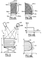
- Figure 2A shows the shape of a 12m fendi with a 12mC1 side is straight because resulting from the sawing of the block, comes the fendi 12m; the other sides 12mC2, 12mC3, 12mC4 have a more or less regular rounded shape.
- Figure 2B shows another form of fendi 12n also having a straight 12nC1 side, resulting from sawing and two sides 12nC2, 12nC3, irregular.
- this fendi 12n we have depicted the layout of a so-called “tortoise shell” (schuppen) having two straight sides and a rounded side.
- Figure 3 shows schematically the device form 2 analysis including the receiving surface in form of roller table or conveyor 21 mounted on a lifting device shown schematically by scissor rods 23 but which can be any rack and pinion device or with mechanical or electric actuator, or even pneumatic.
- the conveyor 21 is provided with an edge 210 forming a reference side, for example for slits having a right side resulting from sawing.
- the transmitter 22E is shown pivoting. This transmitter can be controlled in rotation by a 220E motor which ensures pivoting in the direction of the curved arrow as well as the transverse tilt to draw the scan lines.
- the receiver 22R is preferably fixed. He covers an area larger than the largest possible area of a fendi to be analyzed and each time receives the image of a trace of analysis of the transmitter 22E.
- the fendi 12f from above the pile of fendis 12 carried by the conveyor 21, is at a reference height H0.
- This reference height can be defined by a mechanical probe which controls the lifting mechanism 23 or by an infrared detector, placed above the battery of cleavings 12.
- This defined position, identical for all splits to be detected, is advantageously chosen so that the form 2 analysis device can provide not only an image of the outline of the fendi except for a homothety but a exact image of the size of the fendi and define the outline of instructions for slate to be cut in this fendi 12f.
- Figure 4A shows in a coordinate system (OX, OY), traces of the transverse scan of the fendi 12f. These traces carry the reference yi, associated with the coordinate of each scan line along the Y axis. scan trace allows to define the xi coordinate of the scan line yi along the OX axis and by cumulative points (xi, yi), the outline of the outline Ci of the fendi 12f.
- Figure 4A like the previous figures, shows a fendi 12f with a right side of sawing aligned with the OY axis.
- the 22R receiver receives the image of the yi line on the fendi.
- This line is straight on the surface of the fendi and due to the thickness of the fendi and the inclination of the beam emitted by the 22E transmitter, this line is distorted at ends of the fendi.
- Each Yi line has two points of discontinuity of abscissas who see the image of the edges of the fendi. Their interpolation between these points is the outline of the fendi.
- the left side of the fendi is aligned on a mark at more or less ten degrees, so that all the first discontinuity points of the lines yi are aligned and correspond for their abscissa to the origin O of contact information.
- This detection is extremely fast and it takes done in masked time, during the realization of the contour of the slate from the previous fendi in the rounding device 4.
- Figures 5A, 5B show an example of a device 4.
- This device consists of a cutout 41 and a rounding tool 42, both mounted coaxially on the same axis 43 of an electric motor 44.
- the disc of the rounding tool 42 is a toothed disc such a saw disc while the cutting tool 41 is composed of radial arms 411 carrying weights 412. These weights strike the fendi to break it along a line located beyond the final outline of the slate; the latter is achieved by the rounding tool 42 which at the same time ensures the final layout and rounding.
- the fendi 12dr being processed in the device 4 is supported at the line of action (LA) of the rounding or nibbling tool 42 by a support in disc shape 45, free in rotation which, by ensuring a relatively punctual contact with the underside of the fendi, contributes to the quality of the spall (bevel given to split by the rounding machine).
- LA line of action
- a conveyor 46 for removing debris.
- the device 4 is also covered by a protective cover 47 against projections and forming hood for dust extraction and sound insulation.
- Figure 5B shows in more detail the work of the rolling device 4 on a fendi 12dr, held by the suction cup 53 of the arm 52 of the first transfer device 5.
- the transfer device 5 holds the fendi 12dr during the entire cutting operation and and presents it appropriately to guide it during this operation, the cutting tools 41 and rounding 42 being fixed.
- the cutting tool 41 ( Figure 5B) roughs the shape of the fendi by removing the most important part corresponding to the band z1, leaving no subsistence that a thin strip z2 beyond the 12dr1 contour that we want give this place to the slate.
- the cutting tool 41 strike the part of the fendi in the z1 strip to break the large pieces.
- Band z2 is a protection zone for avoid any cracks, which could occur in the zend band of the fendi, does not propagate beyond the final contour 12dr1.
- the rounding is carried out by the rounding tool 42 which is in fact a nibbler; this one works in a much finer and less brutal way, too, in progressing, does this tool 42 not risk creating cracks propagating beyond the line 12dr1, towards inside the slate, the support 45 prohibiting this spread.
- the vector Vi plotted on the suction cup 53 of the device transfer 5 shows that the fendi 12dr is oriented precisely.
- the fendi 12dr is moved in the AR direction.
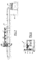
- FIG. 6 shows an example of installation of automatic production of slates according to the invention. This installation consists of the same elements as those already described above which bear the same references. The differences will be discussed below in more detail while the common parts will simply be cited.
- the input conveyor 1, ensuring storage is preceded by a roller conveyor 101, powered from an automatic tiering machine 9 or from a manual slitting machine 91.
- the tiercer 9 is for example made like the one shown Figures 9 and 10 and its description will be made later.
- the semi-automatic slitting machine 91 receives jets or double jets for hand split.
- Such a machine is known per se and does not no detailed description required. She generally works by depression and impaction.
- the suction cups have been specially modified for this application, which consists in splitting slits of any shape whereas all the fendis treated so far by de such machines are rectangular slits.
- the overall shape suction cups has been reduced to be able to attach to splits of any shape, even reduced.
- the slits obtained in this machine 91 are deposited on a tray of a translation table 102 which inserts the piles of fendis loaded on the trays in the conveyor 1.
- the figure shows the different segments of the conveyor 1 driven by motors 103.
- the first transfer means 6 is simply shown by a circle. It supplies the rounding device 4.
- the first transfer means 6 deposits the slates on table 63 hence the third transfer means 7, also schematized simply by a circle, takes the slates to pass them either to the discharge discharge F5 which brings rejected products back to the entry level semi-automatic station 91 to carry out any treatment manual to recover a slate in a fendi having a default.
- the third transfer means 7 also passes slates according to the classification carried out by the processing circuit of the control device not shown, to outputs F1, F2, F3, F4 ... corresponding to the different types of slate to make. Then the slates are recovered to be packaged.
- the installation includes a cabinet power 300 for the various electrical circuits.
- FIG. 7 The sectional view of Figure 7 shows more particularly the input conveyor 1 and its various motors 103 as well as the form 2 analysis device with the plate cleavage elevator.
- the waste conveyor 46 is shown. It leads to the evacuation conveyor 200, housed at this location in a false 201 so that the waste conveyor 46 can travel in a horizontal position, above from the workshop floor.
- the evacuation conveyor 200 is in fact inclined. He comes out of false 201 to rise above a dumpster.
- Figure 8 is a side view of the device of shape analysis showing the plate 21 and the device elevator.
- the plate 21 is carried by a console 211 mounted on a guide column 212, the assembly being actuated by a screw jack controlled by an electric motor 213.
- Figures 9 and 10 show an exemplary embodiment a tiercer 9. It is intended to operate automatically to tier slate blocks previously peeled and having at least one sawn side.
- the machine has two parts, a 92 slot system and a block 93 holding system.
- the slot system includes an impact cylinder 921 carrying a slot chisel 922, the assembly being mounted on a plate 923 animated by a displacement vertical defined.
- the horizontal 922 slot chisel is associated with a vertical shield 924 against which is pushed the sawn face of the block to be tiered, not shown.
- Tiering starts from the top and with each operation the tray 923 carried by columns 925, descends one notch. Movement vertical of the plate 923 is ensured by a ball screw, driven by a brushless motor.
- the other parts of installation, upstream, in particular saws for cutting the blocks are not described in detail.
- the block placed on a roller track 932 is held by the holding system 93 formed of a set of independent cylinders 931 (FIG. 10), pushing the block forward, with its sawn face resting against the shield 924.
- This machine is controlled by the automaton of the part of the processing circuit and ordered.
- the tiercer 9 receives a shale block, peeled and sawn. This block is presented horizontally; he rests on its fissility plane. After its installation, the cylinders 931 block it against the shield 924 which is placed at the proper height to make the first slit. Then, the clamping by the cylinders 931 is released then the plate step down to split the throw or double throw next. This machine delivers a block per minute in a single jet, or a jet every two seconds.
- the positioning of the block is done by hand or automatically by slaving the support conveyor to a block positioning device at the start of operations, and the height of the block is identified by the detection of the higher fissile plane. Then the operation of the tiercer machine is done automatically.
Landscapes
- Engineering & Computer Science (AREA)
- Mining & Mineral Resources (AREA)
- Mechanical Engineering (AREA)
- Sorting Of Articles (AREA)
- Fertilizers (AREA)
- Length Measuring Devices By Optical Means (AREA)
- Curing Cements, Concrete, And Artificial Stone (AREA)
- Treatment Of Fiber Materials (AREA)
- Laser Beam Processing (AREA)
Claims (13)
- Verfahren zur automatischen Herstellung von Schieferplatten aus Restschiefermaterial aus kleinen Blöcken, die aus Ausschüssen der herkömmlichen Herstellung bestehen, wobeieine automatische Formanalyse jedes Restschiefermaterials durchgeführt wird, um seinen Umriß zu definieren,jedem Restschiefermaterial ein Sollumriß zugewiesen wird, der der optimalen Schieferplatte entspricht, die dieses Restschiefermaterial ergeben kann,der grobe Umriß der Schieferplatte zugeschnitten wird, indem ein Schutzstreifen jenseits des Sollumrisses der Schieferplatte belassen wird, und sodann der endgültige Umriß zugeschnitten wird und die Spur abgerundet wird,die hergestellte Schieferplatte kontrolliert wird, indem sie mit dem Sollumriß verglichen wird,die Schieferplatte entsprechend dem Ergebnis der Kontrolle eingestuft wird.
- Verfahren nach Anspruch 1, dadurch gekennzeichnet, daß die Formanalyse durch ein optisches Abtasten des Restschiefermaterials und durch die Auswertung des Abtastsignals erfolgt.
- Verfahren nach Anspruch 2, dadurch gekennzeichnet, daß dieses optische Abtasten des Restschiefermaterials mit einer Lichtquelle erfolgt, die ein Bündel aussendet, mit dem die Oberfläche des Restschiefermaterials abgetastet wird.
- Verfahren nach Anspruch 2, dadurch gekennzeichnet, daß das Abtasten des Restschiefermaterials durchgeführt wird, indem auf dieses ein Netz von parallelen Linien projiziert wird.
- Anlage zur automatischen Herstellung von Schieferplatten aus Restschiefermaterial aus kleinen Blöcken, die aus Ausschüssen der herkömmlichen Herstellung bestehen, umfassend:A) eine Formanalysevorrichtung (2) miteiner Oberfläche zur Aufnahme des Restschiefermaterials (21),einem optischen Analysator (22), der den Umriß des Restschiefermaterials (12f) ermittelt,einem Verarbeitungs- und Steuerkreis (3), derdie Signale (S1) des Analysators empfängt und den Umriß des Restschiefermaterials definiert,den Typ der Schieferplatte bestimmt, der aus diesem Restschiefermaterial gebildet werden kann, unddiese Daten und die ausgerichtete Position des Restschiefermaterials (12f) aufzeichnet,B) eine Abrundungsvorrichtung (4) stromabwärts von der Formanalysevorrichtung, umfassendein Zuschneideorgan (41), um den groben Umriß der Schieferplatte gemäß dem Sollumriß zuzuschneiden, der vom Verarbeitungskreis (3) der Formanalysevorrichtung definiert wurde,eine Aushauschere, die stromabwärts vom Zuschneideorgan das Schieferplatten-Vorprodukt aushaut und abrundet, um eine Schieferplatte zu ergeben, und das Restschiefermaterial bearbeitet,C) eine Kontrollvorrichtung (6) stromabwärts von der Abrundungsvorrichtung (4), umfassendeinen optischen Analysator (62), um die hergestellte Schieferplatte (12g) zu analysieren und ein Analysesignal (S2) zu liefern,einen Verarbeitungskreis, derdas Analysesignal empfängt und es mit einem der Sollform des Schieferplattentyps entsprechenden Sollsignal vergleicht, das von der Formanalysevorrichtung (2) erstellt wurde,die Schieferplatte in Abhängigkeit vom Ergebnis dieses Vergleichs (F1, F2, F3) einstuft,D) eine Übergabeanlage, umfassend:ein erstes Übergabemittel (5) zwischen der Formanalysevorrichtung (2) und der Abrundungsvorrichtung (4),das das Restschiefermaterial (12f) in der Analysevorrichtung (2) nimmt, um es dem Zuschneideorgan (41) und der Aushauschere (42) der Abrundungsvorrichtung (4) zu präsentieren, indem es das Restschiefermaterial während dieses Vorgangs hält und führt, und um sodann die Schieferplatte (12g) nach der Abrundung in einer ausgerichteten Position in der Kontrollvorrichtung (6) abzulegen,einen Kreis zur Steuerung des ersten Übergabemittels (5), um dieses die Bewegungen des Ergreifens des Restschiefermaterials, des Haltens des Restschiefermaterials in der Abrundungsvorrichtung und des Nachführens des Wegs gemäß der der Schieferplatte zu verleihenden Form ausführen zu lassen und um die Schieferplatte in einer ausgerichteten Position in der Kontrollvorrichtung abzulegen,ein zweites Übergabemittel, das die Aufnahmefläche (63) des Kontrollmittels darstellt, um die Schieferplatte zur Kontrollanalyse aufzunehmen und um sie an ein drittes Übergabemittel (7) weiterzugeben,einen Kreis zur Steuerung dieses zweiten Übergabemittels in Abhängigkeit von der Bewegung des ersten Übergabemittels und zur Gewährleistung der Bewegung der Schieferplatte in der definierten ausgerichteten Position,ein drittes Übergabemittel (7) zwischen der Kontrollvorrichtung (6) und dem Ausgang, das die Schieferplatte vom zweiten Übergabemittel übernimmt, um sie auf selektive Weise in Abhängigkeit von den Kontrollergebnissen zum Ausgang weiterzuleiten.
- Anlage nach Anspruch 5, dadurch gekennzeichnet, daß der optische Analysator (22) umfaßt:einen Sender (22R) mit einer Quelle eines Lichtbündels, das dazu bestimmt ist, die Oberfläche des Restschiefermaterials (12f) abzutasten,einen Empfänger (22R), der das Abtastsignal empfängt, das vom Sender auf dem Restschiefermaterial gezeichnet wurde, und ein Erfassungssignal (S1) für den Verarbeitungs- und Steuerkreis (3) liefert.
- Anlage nach Anspruch 6, dadurch gekennzeichnet, daß der Sender (22R), der ein Lichtbündel liefert, auf einem schwingenden Träger (220E) montiert ist, der das transversale Abtasten steuert.
- Anlage nach Anspruch 5, dadurch gekennzeichnet, daß die Abrundungsvorrichtung (4) umfaßt:ein Zuschneidewerkzeug (42), das aus rotierenden Hämmern (422) gebildet ist, die durch eine Achse (43) getragen werden, die durch einen Motor (44) angetrieben wird, wobei das Zuschneidewerkzeug (42) einen breiten Bereich (z1) des Restschiefermaterials jenseits eines schmalen Schutzstreifens (z2) loslöst, der von außen an die Seite (12dr1) der in Herstellung befindlichen Schieferplatte angrenzt,ein Abrundungswerkzeug (41) in Form einer Zahnscheibe, um das schmale Band (z2) zu entfernen, das vom Zuschneidewerkzeug (42) belassen wurde, und gleichzeitig für die Abrundung der entsprechenden Seite der Schieferplatte zu sorgen, wobei dieses schmale Band (z2) vom Abrundungswerkzeug (41) entfernt wird,eine bewegliche Auflage (45), gebildet durch eine Gegenscheibe, die im Bereich der Wirkungslinie des Abrundungswerkzeugs (41) unter dem Restschiefermaterial angeordnet ist, um den Rand des Restschiefermaterials im Lauf des Aushauens zu stützen.
- Anlage nach Anspruch 5, dadurch gekennzeichnet, daß der optische Kontrollanalysator (62) umfaßt: einen Sender (62E), der ein Lichtbündel aussendet, das dazu bestimmt ist, die Schieferplatte (12a) abzutasten, und einen optischen Empfänger (62R), der das Abtastbild empfängt, um ein Erfassungssignal (S2) an den Verarbeitungs- und Steuerkreis (3) zu senden.
- Anlage nach Anspruch 5, dadurch gekennzeichnet, daß das erste und das dritte Übergabemittel (5, 7) durch einen Roboter gebildet sind, der eine Säule (51, 71) umfaßt, der einen Arm (52, 72) trägt, der in einem Saugnapf (53, 73) endet, dessen Position und Ausrichtung definiert sind, wobei sich die Aktionsradien der beiden Roboter nicht überschneiden.
- Anlage nach Anspruch 5, dadurch gekennzeichnet, daß das zweite Übergabemittel (63) eine translationsbewegliche Platte (61) ist.
- Anlage nach Anspruch 5, dadurch gekennzeichnet, daß sie eine Bohrvorrichtung umfaßt, um in den Schieferplatten (12a) an definierten Stellen Nagelungslöcher zu bilden.
- Anlage nach Anspruch 5, dadurch gekennzeichnet, daß der Einlass (1) für das Restschiefermaterial mit einer Spaltmaschine ausgestattet ist.
Applications Claiming Priority (2)
| Application Number | Priority Date | Filing Date | Title |
|---|---|---|---|
| FR9913014A FR2799683B1 (fr) | 1999-10-19 | 1999-10-19 | Procede et installation de fabrication automatique d'ardoises a partir de fendis |
| FR9913014 | 1999-10-19 |
Publications (2)
| Publication Number | Publication Date |
|---|---|
| EP1093899A1 EP1093899A1 (de) | 2001-04-25 |
| EP1093899B1 true EP1093899B1 (de) | 2004-05-12 |
Family
ID=9551089
Family Applications (1)
| Application Number | Title | Priority Date | Filing Date |
|---|---|---|---|
| EP00402869A Expired - Lifetime EP1093899B1 (de) | 1999-10-19 | 2000-10-17 | Verfahren und Anlage zur automatischen Herstellung von Schieferplatten aus Restschiefermaterial |
Country Status (5)
| Country | Link |
|---|---|
| EP (1) | EP1093899B1 (de) |
| AT (1) | ATE266511T1 (de) |
| DE (1) | DE60010619D1 (de) |
| ES (1) | ES2220364T3 (de) |
| FR (1) | FR2799683B1 (de) |
Families Citing this family (4)
| Publication number | Priority date | Publication date | Assignee | Title |
|---|---|---|---|---|
| DE10236583B3 (de) * | 2002-08-08 | 2004-02-05 | Schiefergruben Magog Gmbh & Co. Kg | Verfahren und Vorrichtung zur automatischen, computergestützten Zurichtung von Schieferplatten |
| US7854097B2 (en) | 2004-01-16 | 2010-12-21 | Jeld-Wen, Inc. | Simulated divided light products and processes and systems for making such products |
| US7640073B2 (en) | 2005-04-14 | 2009-12-29 | Jeld-Wen, Inc. | Systems and methods of identifying and manipulating objects |
| PT3040172T (pt) * | 2014-12-05 | 2022-12-20 | Remo Pisetta | Instalação e processo de processamento de bloco |
Family Cites Families (4)
| Publication number | Priority date | Publication date | Assignee | Title |
|---|---|---|---|---|
| US4221974A (en) * | 1979-02-02 | 1980-09-09 | The Bendix Corporation | Lumber inspection and optimization system |
| FR2585982B1 (fr) * | 1985-08-06 | 1988-07-15 | Angers Ardoisieres | Installation de fabrication de produits ardoisiers, tels que des ardoises, des elements de revetement ou de decoration |
| ES1001589Y (es) * | 1987-02-10 | 1989-01-01 | Rathscheck Pizarras, S.A. (Rapida) | Dispositivo de corte para elaborar los bordes de piezas de pizarra |
| DE4102721A1 (de) * | 1991-01-30 | 1992-08-06 | Rosenthal Ag | Verfahren und vorrichtung zur erzeugung einer sollkontur an einem werkstueck |
-
1999
- 1999-10-19 FR FR9913014A patent/FR2799683B1/fr not_active Expired - Fee Related
-
2000
- 2000-10-17 DE DE60010619T patent/DE60010619D1/de not_active Expired - Lifetime
- 2000-10-17 EP EP00402869A patent/EP1093899B1/de not_active Expired - Lifetime
- 2000-10-17 AT AT00402869T patent/ATE266511T1/de not_active IP Right Cessation
- 2000-10-17 ES ES00402869T patent/ES2220364T3/es not_active Expired - Lifetime
Also Published As
| Publication number | Publication date |
|---|---|
| EP1093899A1 (de) | 2001-04-25 |
| ES2220364T3 (es) | 2004-12-16 |
| ATE266511T1 (de) | 2004-05-15 |
| FR2799683B1 (fr) | 2001-12-07 |
| DE60010619D1 (de) | 2004-06-17 |
| FR2799683A1 (fr) | 2001-04-20 |
Similar Documents
| Publication | Publication Date | Title |
|---|---|---|
| EP3049794B1 (de) | Inspektionsverfahren und inspektionslinie für reifen | |
| CA1246427A (fr) | Procede de fabrication de lames rainurees ou moulurees telles que lames de volets, moulures de menuiserie ou de batiment et dispositif pour la mise en oeuvre de ce procede | |
| KR101396915B1 (ko) | 취성 재료 할단 방법 및 그 장치 | |
| WO2011124782A1 (fr) | Procede et dispositif de transfert de decoupes pour boites d'emballage | |
| WO2000078512A1 (fr) | Procede et installation pour la decoupe et le dechargement automatique de piles de pieces dans un matelas de matiere en feuille | |
| US20080017276A1 (en) | Log positioning apparatus and associated method | |
| FR2587318A1 (fr) | Procede et machine pour la fabrication de pieces creuses de revolution formees de fils s'etendant selon trois directions differentes. | |
| EP1093899A1 (de) | Verfahren und Anlage zur automatischen Herstellung von Schieferplatten aus Restschiefermaterial | |
| EP2589474A1 (de) | Automatisiertes Verfahren zum Einfügen von Isolierkörpern in die Hohlräume von Blockbausteinen, und Produktionslinie zum automatischen Einfügen für die Umsetzung dieses Verfahrens | |
| FR2748413A3 (fr) | Machne a decouper les panneaux et procede correspondant | |
| JP5381046B2 (ja) | 半導体ウェーハのスクライブ装置、およびそれを備えたスクライブシステム | |
| FR2576528A1 (fr) | Procede de traitement pour la segregation d'objets | |
| KR101452773B1 (ko) | 자동제어 서까래 가공장치 | |
| EP0912305B1 (de) | Verfahren und vorrichtung zum herstellen von fassdauben | |
| EP2772143B1 (de) | Verfahren und Anlage zum Entfernen der Strünke von ausgewachsenen Salatköpfen | |
| FR2651163A1 (fr) | Dispositif pour recevoir et transferer des pieces a la sortie d'une tronconneuse. | |
| FR3078499A1 (fr) | Machine de dressage de merrains | |
| EP1232818A1 (de) | Verfahren und Einrichtung zum Schneiden eines Baumstammes | |
| EP1258306A2 (de) | System zur Erfassung von Ungleichmässigkeiten in den Abmessungen von getrennten Brettern | |
| WO2025153706A1 (fr) | Dispositif de préhension | |
| FR2990373A1 (fr) | Installation de sciage de grumes, et procede de sciage d'une grume | |
| CA1144352A (fr) | Methode et appareil pour la construction de sieges pour chaises en bois | |
| FR2712210A1 (fr) | Appareil et procédé automatique de trri par couleur pour trier et récupérer des tessons. | |
| FR2975321A1 (fr) | Procede et installation de fabrication de pieces de serie suivant des specifications d'equilibrage determinees | |
| FR2560808A1 (fr) | Procede d'optimisation du rendement en bois dans le sciage en long des grumes, et d'installation de sciage mettant en oeuvre ce procede |
Legal Events
| Date | Code | Title | Description |
|---|---|---|---|
| PUAI | Public reference made under article 153(3) epc to a published international application that has entered the european phase |
Free format text: ORIGINAL CODE: 0009012 |
|
| AK | Designated contracting states |
Kind code of ref document: A1 Designated state(s): AT BE CH CY DE DK ES FI GB GR IE IT LI LU MC NL PT SE |
|
| AX | Request for extension of the european patent |
Free format text: AL;LT;LV;MK;RO;SI |
|
| 17P | Request for examination filed |
Effective date: 20010924 |
|
| AKX | Designation fees paid |
Free format text: AT BE CH CY DE DK ES FI GB GR IE IT LI LU MC NL PT SE |
|
| RIN1 | Information on inventor provided before grant (corrected) |
Inventor name: VEDIE, JACQUES JEAN |
|
| GRAP | Despatch of communication of intention to grant a patent |
Free format text: ORIGINAL CODE: EPIDOSNIGR1 |
|
| GRAS | Grant fee paid |
Free format text: ORIGINAL CODE: EPIDOSNIGR3 |
|
| GRAA | (expected) grant |
Free format text: ORIGINAL CODE: 0009210 |
|
| AK | Designated contracting states |
Kind code of ref document: B1 Designated state(s): AT BE CH CY DE DK ES FI GB GR IE IT LI LU MC NL PT SE |
|
| PG25 | Lapsed in a contracting state [announced via postgrant information from national office to epo] |
Ref country code: IT Free format text: LAPSE BECAUSE OF FAILURE TO SUBMIT A TRANSLATION OF THE DESCRIPTION OR TO PAY THE FEE WITHIN THE PRESCRIBED TIME-LIMIT;WARNING: LAPSES OF ITALIAN PATENTS WITH EFFECTIVE DATE BEFORE 2007 MAY HAVE OCCURRED AT ANY TIME BEFORE 2007. THE CORRECT EFFECTIVE DATE MAY BE DIFFERENT FROM THE ONE RECORDED. Effective date: 20040512 Ref country code: FI Free format text: LAPSE BECAUSE OF FAILURE TO SUBMIT A TRANSLATION OF THE DESCRIPTION OR TO PAY THE FEE WITHIN THE PRESCRIBED TIME-LIMIT Effective date: 20040512 Ref country code: IE Free format text: LAPSE BECAUSE OF FAILURE TO SUBMIT A TRANSLATION OF THE DESCRIPTION OR TO PAY THE FEE WITHIN THE PRESCRIBED TIME-LIMIT Effective date: 20040512 Ref country code: AT Free format text: LAPSE BECAUSE OF FAILURE TO SUBMIT A TRANSLATION OF THE DESCRIPTION OR TO PAY THE FEE WITHIN THE PRESCRIBED TIME-LIMIT Effective date: 20040512 Ref country code: NL Free format text: LAPSE BECAUSE OF FAILURE TO SUBMIT A TRANSLATION OF THE DESCRIPTION OR TO PAY THE FEE WITHIN THE PRESCRIBED TIME-LIMIT Effective date: 20040512 Ref country code: CY Free format text: LAPSE BECAUSE OF FAILURE TO SUBMIT A TRANSLATION OF THE DESCRIPTION OR TO PAY THE FEE WITHIN THE PRESCRIBED TIME-LIMIT Effective date: 20040512 Ref country code: GB Free format text: LAPSE BECAUSE OF FAILURE TO SUBMIT A TRANSLATION OF THE DESCRIPTION OR TO PAY THE FEE WITHIN THE PRESCRIBED TIME-LIMIT Effective date: 20040512 |
|
| REG | Reference to a national code |
Ref country code: GB Ref legal event code: FG4D Free format text: NOT ENGLISH |
|
| REG | Reference to a national code |
Ref country code: CH Ref legal event code: EP |
|
| REG | Reference to a national code |
Ref country code: IE Ref legal event code: FG4D Free format text: FRENCH |
|
| REF | Corresponds to: |
Ref document number: 60010619 Country of ref document: DE Date of ref document: 20040617 Kind code of ref document: P |
|
| PG25 | Lapsed in a contracting state [announced via postgrant information from national office to epo] |
Ref country code: SE Free format text: LAPSE BECAUSE OF FAILURE TO SUBMIT A TRANSLATION OF THE DESCRIPTION OR TO PAY THE FEE WITHIN THE PRESCRIBED TIME-LIMIT Effective date: 20040812 Ref country code: GR Free format text: LAPSE BECAUSE OF FAILURE TO SUBMIT A TRANSLATION OF THE DESCRIPTION OR TO PAY THE FEE WITHIN THE PRESCRIBED TIME-LIMIT Effective date: 20040812 Ref country code: DK Free format text: LAPSE BECAUSE OF FAILURE TO SUBMIT A TRANSLATION OF THE DESCRIPTION OR TO PAY THE FEE WITHIN THE PRESCRIBED TIME-LIMIT Effective date: 20040812 |
|
| PG25 | Lapsed in a contracting state [announced via postgrant information from national office to epo] |
Ref country code: DE Free format text: LAPSE BECAUSE OF FAILURE TO SUBMIT A TRANSLATION OF THE DESCRIPTION OR TO PAY THE FEE WITHIN THE PRESCRIBED TIME-LIMIT Effective date: 20040813 |
|
| PG25 | Lapsed in a contracting state [announced via postgrant information from national office to epo] |
Ref country code: LU Free format text: LAPSE BECAUSE OF NON-PAYMENT OF DUE FEES Effective date: 20041017 |
|
| PG25 | Lapsed in a contracting state [announced via postgrant information from national office to epo] |
Ref country code: CH Free format text: LAPSE BECAUSE OF NON-PAYMENT OF DUE FEES Effective date: 20041031 Ref country code: BE Free format text: LAPSE BECAUSE OF NON-PAYMENT OF DUE FEES Effective date: 20041031 Ref country code: LI Free format text: LAPSE BECAUSE OF NON-PAYMENT OF DUE FEES Effective date: 20041031 Ref country code: MC Free format text: LAPSE BECAUSE OF NON-PAYMENT OF DUE FEES Effective date: 20041031 |
|
| NLV1 | Nl: lapsed or annulled due to failure to fulfill the requirements of art. 29p and 29m of the patents act | ||
| GBV | Gb: ep patent (uk) treated as always having been void in accordance with gb section 77(7)/1977 [no translation filed] |
Effective date: 20040512 |
|
| REG | Reference to a national code |
Ref country code: ES Ref legal event code: FG2A Ref document number: 2220364 Country of ref document: ES Kind code of ref document: T3 |
|
| REG | Reference to a national code |
Ref country code: IE Ref legal event code: FD4D |
|
| PLBE | No opposition filed within time limit |
Free format text: ORIGINAL CODE: 0009261 |
|
| STAA | Information on the status of an ep patent application or granted ep patent |
Free format text: STATUS: NO OPPOSITION FILED WITHIN TIME LIMIT |
|
| BERE | Be: lapsed |
Owner name: *SOVEMINE INGENIERIE Effective date: 20041031 |
|
| 26N | No opposition filed |
Effective date: 20050215 |
|
| REG | Reference to a national code |
Ref country code: CH Ref legal event code: PL |
|
| BERE | Be: lapsed |
Owner name: *SOVEMINE INGENIERIE Effective date: 20041031 |
|
| PG25 | Lapsed in a contracting state [announced via postgrant information from national office to epo] |
Ref country code: PT Free format text: LAPSE BECAUSE OF NON-PAYMENT OF DUE FEES Effective date: 20041012 |
|
| PGFP | Annual fee paid to national office [announced via postgrant information from national office to epo] |
Ref country code: ES Payment date: 20091022 Year of fee payment: 10 |
|
| REG | Reference to a national code |
Ref country code: ES Ref legal event code: FD2A Effective date: 20111118 |
|
| PG25 | Lapsed in a contracting state [announced via postgrant information from national office to epo] |
Ref country code: ES Free format text: LAPSE BECAUSE OF NON-PAYMENT OF DUE FEES Effective date: 20101018 |