EP1094552A2 - Verbinder für das Verbinden eines Leiters mit einem Bauteil - Google Patents
Verbinder für das Verbinden eines Leiters mit einem Bauteil Download PDFInfo
- Publication number
- EP1094552A2 EP1094552A2 EP00870238A EP00870238A EP1094552A2 EP 1094552 A2 EP1094552 A2 EP 1094552A2 EP 00870238 A EP00870238 A EP 00870238A EP 00870238 A EP00870238 A EP 00870238A EP 1094552 A2 EP1094552 A2 EP 1094552A2
- Authority
- EP
- European Patent Office
- Prior art keywords
- conductor
- shaped frame
- frame
- flange
- structural member
- Prior art date
- Legal status (The legal status is an assumption and is not a legal conclusion. Google has not performed a legal analysis and makes no representation as to the accuracy of the status listed.)
- Withdrawn
Links
Images


Classifications
-
- H—ELECTRICITY
- H01—ELECTRIC ELEMENTS
- H01R—ELECTRICALLY-CONDUCTIVE CONNECTIONS; STRUCTURAL ASSOCIATIONS OF A PLURALITY OF MUTUALLY-INSULATED ELECTRICAL CONNECTING ELEMENTS; COUPLING DEVICES; CURRENT COLLECTORS
- H01R4/00—Electrically-conductive connections between two or more conductive members in direct contact, i.e. touching one another; Means for effecting or maintaining such contact; Electrically-conductive connections having two or more spaced connecting locations for conductors and using contact members penetrating insulation
- H01R4/10—Electrically-conductive connections between two or more conductive members in direct contact, i.e. touching one another; Means for effecting or maintaining such contact; Electrically-conductive connections having two or more spaced connecting locations for conductors and using contact members penetrating insulation effected solely by twisting, wrapping, bending, crimping, or other permanent deformation
- H01R4/18—Electrically-conductive connections between two or more conductive members in direct contact, i.e. touching one another; Means for effecting or maintaining such contact; Electrically-conductive connections having two or more spaced connecting locations for conductors and using contact members penetrating insulation effected solely by twisting, wrapping, bending, crimping, or other permanent deformation by crimping
- H01R4/183—Electrically-conductive connections between two or more conductive members in direct contact, i.e. touching one another; Means for effecting or maintaining such contact; Electrically-conductive connections having two or more spaced connecting locations for conductors and using contact members penetrating insulation effected solely by twisting, wrapping, bending, crimping, or other permanent deformation by crimping for cylindrical elongated bodies, e.g. cables having circular cross-section
- H01R4/186—Electrically-conductive connections between two or more conductive members in direct contact, i.e. touching one another; Means for effecting or maintaining such contact; Electrically-conductive connections having two or more spaced connecting locations for conductors and using contact members penetrating insulation effected solely by twisting, wrapping, bending, crimping, or other permanent deformation by crimping for cylindrical elongated bodies, e.g. cables having circular cross-section using a body comprising a plurality of cable-accommodating recesses or bores
-
- H—ELECTRICITY
- H01—ELECTRIC ELEMENTS
- H01R—ELECTRICALLY-CONDUCTIVE CONNECTIONS; STRUCTURAL ASSOCIATIONS OF A PLURALITY OF MUTUALLY-INSULATED ELECTRICAL CONNECTING ELEMENTS; COUPLING DEVICES; CURRENT COLLECTORS
- H01R4/00—Electrically-conductive connections between two or more conductive members in direct contact, i.e. touching one another; Means for effecting or maintaining such contact; Electrically-conductive connections having two or more spaced connecting locations for conductors and using contact members penetrating insulation
- H01R4/58—Electrically-conductive connections between two or more conductive members in direct contact, i.e. touching one another; Means for effecting or maintaining such contact; Electrically-conductive connections having two or more spaced connecting locations for conductors and using contact members penetrating insulation characterised by the form or material of the contacting members
- H01R4/64—Connections between or with conductive parts having primarily a non-electric function, e.g. frame, casing, rail
-
- Y—GENERAL TAGGING OF NEW TECHNOLOGICAL DEVELOPMENTS; GENERAL TAGGING OF CROSS-SECTIONAL TECHNOLOGIES SPANNING OVER SEVERAL SECTIONS OF THE IPC; TECHNICAL SUBJECTS COVERED BY FORMER USPC CROSS-REFERENCE ART COLLECTIONS [XRACs] AND DIGESTS
- Y10—TECHNICAL SUBJECTS COVERED BY FORMER USPC
- Y10T—TECHNICAL SUBJECTS COVERED BY FORMER US CLASSIFICATION
- Y10T29/00—Metal working
- Y10T29/49—Method of mechanical manufacture
- Y10T29/49002—Electrical device making
- Y10T29/49117—Conductor or circuit manufacturing
- Y10T29/49194—Assembling elongated conductors, e.g., splicing, etc.
- Y10T29/49201—Assembling elongated conductors, e.g., splicing, etc. with overlapping orienting
- Y10T29/49202—Assembling elongated conductors, e.g., splicing, etc. with overlapping orienting including oppositely facing end orienting
-
- Y—GENERAL TAGGING OF NEW TECHNOLOGICAL DEVELOPMENTS; GENERAL TAGGING OF CROSS-SECTIONAL TECHNOLOGIES SPANNING OVER SEVERAL SECTIONS OF THE IPC; TECHNICAL SUBJECTS COVERED BY FORMER USPC CROSS-REFERENCE ART COLLECTIONS [XRACs] AND DIGESTS
- Y10—TECHNICAL SUBJECTS COVERED BY FORMER USPC
- Y10T—TECHNICAL SUBJECTS COVERED BY FORMER US CLASSIFICATION
- Y10T403/00—Joints and connections
- Y10T403/71—Rod side to plate or side
- Y10T403/7129—Laterally spaced rods
- Y10T403/7141—Plural channels in connector
Definitions
- the present invention relates to a connector and, more particularly, to a connector for crimping a conductor to a structural member and , still more particularly; to a connector for crimping multiple conductors of different sizes to a structural member .
- Compression connectors are generally well known in the art.
- U.S. Patent No. 5,036,164 to Schrader et al. which discloses a compression ground connector for connecting one or more taps from a single connector to an installation requiring grounding.
- U.S. Patent No. 5,240,423 to Morrison which discloses a grounding connector capable of being clamped to a tapered metallic flange of an I-beam.
- Still another example is U.S. Patent No. 5,552,564 to Schrader et al. which discloses an H-shaped compressible connector having a main body and two pairs of opposed legs extending in opposite directions from the main body. The H-shaped connector is designed to require a relatively small amount of compressive force to be applied to a crimping device to completely close the connector and into connective engagement with conductors.
- the present invention relates to a grounding connector which includes a frame with upper and lower arms cantilevered from a center section to form a channel adapted to receive a section of a structural steel member.
- the frame has a conductor receiving region in each of the cantilevered arms, each conductor receiving region being a slot extending through the frame having a longitudinal axis aligned substantially parallel to the frame.
- the conductor receiving slot on one side of the frame is sized to receive a conductor of a first size and the conductor receiving slot on the other side is sized to receive a conductor of a different size.
- the conductor receiving regions are located so that when the upper arm and the lower arm are compressed to grip the section of the structural steel member received in the channel, the conductor is crimped to the frame.
- the upper and lower arms of the frame have opposed surfaces for engaging the flange of the structural member and at least one of the opposed surfaces has an elongated protrusion such that when the frame is caused to clasp the flange of the structural member, the protrusion provides a slight interference between the width of the U shaped frame and the thickness of the flange of the structural member.
- opposed elongated protrusions are substantially coplanar and may be aligned substantially parallel to the frame or substantially transverse of the frame.
- the invention allows for the attachment of a conductor to a structural steel member by inserting the conductor into a conductor hole in the leg of the connector and placing the connector onto the structural member. The connector is then compressed onto the structural member. During the compression process, the conductor hole is deformed around the conductor thus securing it in place.
- the conductor hole diameter is slightly larger than the diameter of the conductor, large enough so the conductor is readily received into the hole but not so large it subsequently deforms around the conductor in an inadequate manner.
- Another key to the present invention is that, previously, all conductor holes in the structural member were sized for one size conductor only whereas the present invention accommodates various sizes of conductors.
- the novel connector is formed with one conductor hole which can accept, for example, either a #2 AWG solid conductor (.257" dia.) or a #2 AWG stranded conductor (.320" dia.) while the other conductor hole can accept either a #6 AWG solid conductor (.162" dia.) or a #6 AWG stranded conductor (.184" dia.).
- This is accomplished through the use of two protrusions that are parallel to the front surface of the connector that extend outwardly above the conductor holes. During the compression process, the dies of the compression tool interface with these protrusions first.
- a concentrated force is produced which collapses the material of the protrusions into any voids of the conductor hole not occupied by the conductor itself. During the remainder of the crimp process, this material, along with other material around the conductor being securely attached to the connector and the connector/conductor assembly being securely fastened to the structural member.
- the connector In a second instance, the situation is addressed that when installing structural compression connectors, it is desirable for the connector to have the ability to be placed on the structural member and remain temporarily "tacked” in position before being permanently compressed onto the member. This offers the installer the ability to position the conductors into the connector using both hands instead of holding the connector in place with one hand and positioning the conductor with the other. This construction also holds the connector in place while the installer orientates the tool over the connector/conductor assembly and compresses the assembly in place for permanent attachment. This desirable result is accomplished by the invention.
- a protrusion is provided on both the top and bottom surfaces of the groove. This groove may have several different orientations.
- protrusions provide a slight interference between the width of the connector groove and the thickness of the structural member when the connector is placed onto the structural member. Because of the interference fit, the connector may need to be tapped onto the member with the use of a hammer or the like. In this manner, the connector of the invention is temporarily retained in engagement with the structural member before permanent attachment occurs.
- the connector of the invention offers the ability of accepting a continuous run conductor and/or a tap conductor.
- the continuous run hole of a known connector design has been modified to a U-shaped conductor hole to accommodate a continuous run.
- a primary feature, then, of the present invention is the provision of a connector for crimping a conductor to a structural member.
- Another feature of the present invention is the provision of such a connector capable of crimping multiple conductors of different sizes to a structural member
- Still another feature of the present invention is the provision of such a connector being a grounding connector having a frame adapted for clamping to a flange of a structural member, the frame having a general U shape with an upper arm and a lower arm cantilevered from a center section to form opposite sides of the U shaped frame, the opposite sides of the U shaped frame being adapted to clasp therebetween the flange of the structural member when the U shaped frame is clamped to the flange, the U shaped frame having a pair of conductor receiving regions, each to receive a conductor therein, the conductor receiving regions being located, respectively, in the opposite sides of the U shaped frame so that when the opposite sides of the U shaped frame are deformed to clasp the flange of the structural member the conductors located in the conductor receiving regions are crimped to the U shaped frame.
- FIG. 1 there is shown an exploded perspective view of a known connector 10 which is improved by the present invention in a manner to be described below.
- the known connector 10 is used to mechanically and electrically connect a grounding conductor 12 to a railroad rail member 14 or other structural member.
- the conductor 12 is inserted into the connector 10 and the connector 10 is then crimped or compressed onto a portion of the railroad rail member 14.
- the connector 10 is thus mechanically held to the railroad rail member 14.
- This mechanical connection also electrically connects the connector 10 to the railroad rail member 14.
- the conductor 12 is crimped to the connector 10. This operation mechanically and electrically connects the conductor 12 to the connector 10.
- the conductor 12 is connected to the connector 10 and the connector 10 is connected to the railroad rail member 14 in one crimping stroke. Consequently, the conductor 12 is mechanically and electrically connected to the railroad rail member 14, by the connector 10.
- the conductor 12 is grounded such that the rail 14 becomes grounded, and the rail member 14 is grounded by the conductor 12 with one crimping motion.
- the connector 10 has a frame 20 made from a malleable electrically conducting metal.
- the frame 20 is a one-piece member.
- the frame 20 has an upper arm 22 and a lower arm 24 cantilevered from a central web section 26 to form a generally "U" shaped channel 28.
- the lower arm 24 is substantially flat.
- the lower arm 24 has an external surface 30 forming a seating surface 32 of the connector 10.
- the inner surface 34 of the lower arm 24 forms a lower side 36 of the channel 28.
- the web 26 extends between the upper arm 22 and lower arm 24 at a rear end 38 of the frame 20.
- the web 26 is substantially perpendicular to the lower arm 24.
- the face 40 of the web 26 facing the opening 42 of the channel 28 is the bottom 44 of the channel 28.
- the upper arm 22 has a tapered cross-section.
- the outer surface 46 of the upper arm 22 is substantially flat and generally parallel with the seating surface 32 of the connector 10.
- the inner surface 48 of the upper arm 22 forms the upper side 50 of the channel 28.
- the upper side 50 slopes upwards from the bottom 44 of the channel 28 forward to the front end 39 of the frame 20.
- the channel- 28 has a taper which narrows the channel 28 from its opening 42 to the bottom 44.
- the taper of the channel 28 in the connector 10 generally conforms to the taper of the foot flange 60 of the railroad rail member 14; a portion of which is received in the channel 28 (see Fig. 3).
- the railroad rail member 14 has a foot flange 60 supporting a center web 62 with a rail head 64.
- the foot flange 60 has a substantially flat lower seating surface 66.
- the upper surfaces 68 of the foot flange 60 slope downward from the web 62 to the toes 70 of the foot flange 60.
- the slope of the upper surfaces 68 of the foot flange 60 conform to the slope of the upper side 50 of the channel 28 in the connector 10.
- the connector has a slot 80 for receiving the conductor 12 therein.
- the slot 80 is a through slot extending from one side 90A of the connector 10 to the other side 90B.
- the connector receiving slot in the connector may be a partial slot.
- the slot 80 is located in the lower arm 24 of the connector 10, proximate a front face 92 of the lower arm 24 (see Fig. 2).
- the slot 80 has a generally "C" shaped cross-section adapted to admit the conductor 12 therein.
- the front face 92 of the lower arm 24 has an opening 84 therein communicating with the "C" shaped cross-section of the slot 80.
- the opening 84 is sized to exclude the conductor 12 but render the slot 80 sufficiently deformable to crimp the conductor 12 therein, without overly crushing the conductor 12, under compression applied to the external surface 30 and inner surface 34 of the lower arm 24.
- the conductor receiving slot may have any other suitable shape providing a deformable slot for crimping the conductor therein or be located at another position or orientation on the frame.
- the railroad rail member 14 is grounded by connecting the connector 10, with the conductor 12 at least partially attached thereto, to the foot flange 60 of the railroad rail member 14.
- the connector 10 may be attached to either side 72A, B of the foot flange 60.
- the connector 10 is connected to the railroad rail member 14 by inserting frame 20 onto the toe 70 of the foot flange 60 with the toe 70 being received in the channel 28.
- the foot flange 60 is received into the channel 28 until the toe 70 abuts the bottom 44 of the channel 28.
- the slope of the upper side 50 of the channel 28 preferably complements the taper of the foot flange 60 and the lower side 36 of the channel 28 is seated against the lower seating surface 66 of the foot flange 60.
- the conductor 12 is attached to the connector 1 by inserting the conductor into the slot 80. Once the conductor 12 is located in the slot 80 and the connector 10 is positioned on the foot flange 60, the connector 10 is crimped to the foot flange 60. Crimping is accomplished, preferably by a hydraulic or cartridge driven compression tool, by compressing the upper arm 22 and lower arm 24 inward or towards each other to engage the foot flange 60 inside the channel 28.
- the upper 22 and lower 24 arms are deformed with sufficient force to generate grip between the upper surface 68 and lower surface 66 of the foot flange 60 and the upper side 50 and lower side 36 of the channel 28 respectively.
- the connector 10 is mechanically connected to the railroad rail member 14.
- the grounding conductor 12 is inserted into slot 80.
- the crimping stroke that attaches the connector to the rail 14 also effects electrical and mechanical connection between the connector 10 and the conductor 12.
- the bearing forces generated during the crimping stroke between the lower seating surface 66 of the foot flange 60 and the lower side 36 of the channel 28 deforms the slot 80 to crimp the conductor 12 therein.
- the opening 84 of the "C" shaped slot 80 in the front face 92 of the lower arm 24 is closed.
- the conductor 12 is clamped within the connector 10.
- the conductor 12 is mechanically and electrically connected to the connector 10. Consequently, crimping the connector 10 to the foot flange 60 of the railroad rail member 14 establishes both the mechanical and electrical connection between the connector 10 and rail member 14 and the mechanical and electrical connection between the conductor 12 and connector 10.
- the conductor 12 is electrically connected to the rail member 14, thereby grounding the rail member 14 to the conductor 12, with only one crimping stroke.
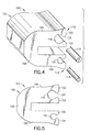
- FIGs. 4 and 5 for a description of a first embodiment of the invention.
- the present invention will be described with reference to the embodiment illustrated in the drawings, it should be understood that the present invention can be embodied in many alternate forms of embodiments.
- any suitable size, shape or type of elements or materials could be used.
- a grounding connector 100 has a frame 102 adapted for clamping to a flange 101 of a structural member which may be of uniform thickness as illustrated or tapered such as the rail member 14.
- the frame 102 has a general U shape with an upper arm 104 and a lower arm 106. Both arms 104, 106 are cantilevered from a center section 108 to form opposite sides of the U shaped frame.
- the opposite sides, or upper arm 104 and lower arm 106, of the U shaped frame 102 are adapted to clasp between them the flange of the structural member.
- the U shaped frame 102 has a pair of conductor receiving regions, 110, 112, respectively, each for engageably receiving an associated conductor 114, 116.
- the conductor receiving regions are located, respectively, in the opposite sides of the U shaped frame 102 so that when the opposite sides of the U shaped frame, that is, the upper and lower arms 104, 106 are deformed to clasp the flange of the structural member, the conductors located in their associated conductor receiving regions are crimped to the U shaped frame.
- one positive feature of the present invention is that the conductor receiving region on one side of the U shaped frame is sized differently than the conductor receiving region on the other side of the U shaped frame.
- the conductor receiving region 110 is a slot 118 having a generally "C" shaped cross section extending through the U shaped frame 102 having a longitudinal axis aligned substantially parallel to the U shaped frame.
- the conductor receiving region 112 is a slot 120 having a generally "C" shaped cross section extending through the U shaped frame 102 having a longitudinal axis aligned substantially parallel to the U shaped frame.
- the slot 118 is sized to receive a conductor 114 of one size while the slot 120 is sized to receive a conductor 116 of a different size. As illustrated, the conductor 114 is of a larger gauge than the conductor 116.
- the upper arm 104 is seen to extend to a front face 122 and has a continuously extending opening 124 enabling communication between the front face and the conductor receiving slot 118 while being sized to exclude the conductor 114 intended to be received in the slot.
- the lower arm 106 extends to a front face 126 and has a continuously extending opening 128 enabling communication between the front face and the conductor receiving slot while being sized to exclude the conductor 116 intended to be received in the slot.
- the grounding connector 200 has a frame 202 adapted for clamping to the flange of a structural member and has a general U shape with an upper arm 204 and a lower arm 206. Both arms 204, 206 are cantilevered from a center section 208 to form opposite sides of the U shaped frame. The opposite sides, or upper arm 204 and lower arm 206, of the U shaped frame 202 are adapted to clasp between them the flange of the structural member.
- the U shaped frame 202 has a pair of conductor receiving regions, 210, 212, respectively, each for engageably receiving an associated conductor.
- the conductor receiving regions are located, respectively, in the opposite sides of the U shaped frame 202 so that when the opposite sides of the U shaped frame, that is, the upper and lower arms 204, 206 are deformed to clasp the flange of the structural member, the conductors located in their associated conductor receiving regions are crimped to the U shaped frame.
- the conductor receiving region on one side of the U shaped frame is sized differently than the conductor receiving region on the other side of the U shaped frame.
- the conductor receiving region 210 is a slot 218 having a generally "U” shaped cross section while the conductor receiving region 212 is a slot 220 having a generally "C” shaped cross section.
- the slot 218 is sized to receive a conductor of one size while the slot 220 is sized to receive a conductor of a different size. Accordingly, the concept of the invention is applicable to grounding connectors whether the conductor receiving slots have a "U" shaped or "C" shaped cross section.
- upper and lower arms 104A, 106A, respectively, of frame 102A have opposed surfaces 130, 132 for engaging the flange of a structural member. At least one of the opposed surfaces 130, 132 has an elongated protrusion 134, although in Fig. 7, one is illustrated in each of the opposed surfaces.
- the protrusion or protrusions 134 provide(s) a slight interference between the width of the U shaped frame and the thickness of the flange of the structural member.
- the protrusions 134 in the opposed surfaces 132 are illustrated as lying in a plane parallel to the plane of the faces 122A, 126A and aligned substantially parallel to the U shaped frame.
- upper and lower arms 104B, 106B, respectively, of frame 102B have opposed surfaces 136, 138 for engaging the flange of the structural member.
- at least one of the opposed surfaces 136, 138 has an elongated protrusion 140, although again in Fig. 8, one is illustrated in each of the opposed surfaces.
- the protrusion or protrusions 140 provide(s) a slight interference between the width of the U shaped frame and the thickness of the flange of the structural member.
- the protrusions 140 in the opposed surfaces 136, 138 are illustrated as being aligned substantially parallel to the U shaped frame 102B at the entrance to the channel 139, and are substantially coplanar.
- upper and lower arms 104C, 106C, respectively, of frame 102C have opposed surfaces 142, 144 for engaging the flange of the structural member. Yet again, at least one of the opposed surfaces 142, 144 has an elongated protrusion 146, although yet again in Fig. 9, one is illustrated in each of the opposed surfaces. Yet again, with such a construction, when the U shaped frame 102C is caused to clasp the flange of the structural member received in a channel 148 at least partially defined by the opposed surfaces 142, 144, the protrusion or protrusions 140 provide(s) a slight interference between the width of the U shaped frame and the thickness of the flange of the structural member.
- the protrusions 146 in the opposed surfaces 142, 144 are illustrated as being aligned substantially parallel to the U shaped frame 102C at the entrance to the channel 148, and are substantially coplanar.
- a modified upper arm 104D includes opposed first and second lip members 150, 152 generally encompassing a conductor receiving slot 154.
- the lip members 150, 152 are mutually configured such that when the opposite sides of the U shaped frame are deformed to clasp the flange of the structural member, the second lip member 152 is rolled into the conductor receiving slot 154 beneath the first lip member 150 and into firm engagement with the conductor 156 received in the conductor receiving slot.
- the first lip member 150 is rolled onto and into firm engagement with the second lip member 152 as seen in Fig. 11.
- a similar operation occurs with respect to a similarly constructed modified lower arm with similar associated lip members and conductor receiving slot.
Landscapes
- Connector Housings Or Holding Contact Members (AREA)
- Multi-Conductor Connections (AREA)
Applications Claiming Priority (2)
| Application Number | Priority Date | Filing Date | Title |
|---|---|---|---|
| US09/422,506 US6303861B1 (en) | 1999-10-21 | 1999-10-21 | Connector for connecting a conductor to a structural member |
| US422506 | 1999-10-21 |
Publications (2)
| Publication Number | Publication Date |
|---|---|
| EP1094552A2 true EP1094552A2 (de) | 2001-04-25 |
| EP1094552A3 EP1094552A3 (de) | 2001-10-24 |
Family
ID=23675191
Family Applications (1)
| Application Number | Title | Priority Date | Filing Date |
|---|---|---|---|
| EP00870238A Withdrawn EP1094552A3 (de) | 1999-10-21 | 2000-10-20 | Verbinder für das Verbinden eines Leiters mit einem Bauteil |
Country Status (2)
| Country | Link |
|---|---|
| US (1) | US6303861B1 (de) |
| EP (1) | EP1094552A3 (de) |
Families Citing this family (5)
| Publication number | Priority date | Publication date | Assignee | Title |
|---|---|---|---|---|
| US6503088B2 (en) * | 2000-12-15 | 2003-01-07 | Di/Dt, Inc. | I-channel surface-mount connector with extended flanges |
| USD670656S1 (en) * | 2010-11-10 | 2012-11-13 | Cadwell Labs | Electrical connector |
| US10985474B2 (en) * | 2018-08-06 | 2021-04-20 | Panduit Corp. | Grounding connector with lock joint |
| US10847960B1 (en) * | 2019-05-16 | 2020-11-24 | Hubbell Incorporated | Multi-directional cable clip |
| EP4256655A4 (de) * | 2020-12-04 | 2024-10-30 | Hubbell Incorporated | Kompressive anschlusspad-montagefläche |
Family Cites Families (10)
| Publication number | Priority date | Publication date | Assignee | Title |
|---|---|---|---|---|
| US3183025A (en) * | 1963-05-16 | 1965-05-11 | Thomas & Betts Corp | Connector with temporary cable holding means |
| US3354517A (en) * | 1966-05-17 | 1967-11-28 | Thomas And Betts Co Inc | Compressible connector |
| US4350843A (en) * | 1978-08-31 | 1982-09-21 | Square D Company | Method and system for crimping a metal connector |
| US4384753A (en) * | 1981-06-26 | 1983-05-24 | Amp Incorporated | Electrical edge connector |
| US5036164A (en) * | 1990-07-25 | 1991-07-30 | Burndy Corporation | Multiple tap ground connector |
| US5103068A (en) * | 1991-02-15 | 1992-04-07 | Burndy Corporation | Connector twist tie |
| PH31141A (en) * | 1991-02-15 | 1998-03-03 | Burndy Corp | Multi-point contact compression connector. |
| US5240423A (en) | 1992-06-19 | 1993-08-31 | Burndy Corporation | Structural steel grounding connector |
| US5552564A (en) | 1994-11-23 | 1996-09-03 | Burndy Corporation | Range enhancement for H-shaped compression connector |
| US5997368A (en) * | 1997-10-28 | 1999-12-07 | Framatome Connectors Usa, Inc. | Connector for connecting a conductor to a structural member |
-
1999
- 1999-10-21 US US09/422,506 patent/US6303861B1/en not_active Expired - Fee Related
-
2000
- 2000-10-20 EP EP00870238A patent/EP1094552A3/de not_active Withdrawn
Also Published As
| Publication number | Publication date |
|---|---|
| US6303861B1 (en) | 2001-10-16 |
| EP1094552A3 (de) | 2001-10-24 |
Similar Documents
| Publication | Publication Date | Title |
|---|---|---|
| US5997368A (en) | Connector for connecting a conductor to a structural member | |
| US5006081A (en) | Electrical wire connector | |
| US6232555B1 (en) | Crimp connection | |
| EP1006613B1 (de) | Verbesserter Messerkontaktsteckverbinder bestehend aus zwei Teilen | |
| US6749457B2 (en) | Crimp terminal | |
| US5044996A (en) | Wedge connector | |
| US7121001B2 (en) | H-tap compression connector | |
| US4723921A (en) | Electrical connector | |
| US6004165A (en) | Multiple cable connector and method therefor | |
| US6649840B2 (en) | Ground bus bar connector | |
| CA2009988C (en) | Electrical connector | |
| EP1267457B1 (de) | Crimpmatrize für elektrisches Anschlussendstück | |
| US6303861B1 (en) | Connector for connecting a conductor to a structural member | |
| US5254021A (en) | Electrical terminal | |
| JPH11505664A (ja) | 電線接続システム | |
| US6482034B2 (en) | Connection structure for electric wire and terminal, connection method therefor and terminal connecting apparatus | |
| US5415015A (en) | Electrical terminal crimping tool | |
| NZ242922A (en) | Electrical wedge connector: wire penetrating teeth at one end of receptacle channels | |
| EP1544965B1 (de) | Ortungseinrichtung für krimpmandrel | |
| JPH0817544A (ja) | バレル端子及び電線接続装置 | |
| JP2000231951A (ja) | 電気コネクタ用端子 | |
| WO1998054790A1 (en) | Crimp connection for large conductors | |
| US5554054A (en) | Temporary terminal retention feature | |
| WO1998009344A1 (en) | Electrical connector | |
| WO2000008716A1 (en) | Insulation displacement device for wire termination |
Legal Events
| Date | Code | Title | Description |
|---|---|---|---|
| PUAI | Public reference made under article 153(3) epc to a published international application that has entered the european phase |
Free format text: ORIGINAL CODE: 0009012 |
|
| AK | Designated contracting states |
Kind code of ref document: A2 Designated state(s): AT BE CH CY DE DK ES FI FR GB GR IE IT LI LU MC NL PT SE |
|
| AX | Request for extension of the european patent |
Free format text: AL;LT;LV;MK;RO;SI |
|
| PUAL | Search report despatched |
Free format text: ORIGINAL CODE: 0009013 |
|
| RIC1 | Information provided on ipc code assigned before grant |
Free format text: 7H 01R 9/03 A, 7H 01R 4/18 B, 7H 01R 4/64 B |
|
| AK | Designated contracting states |
Kind code of ref document: A3 Designated state(s): AT BE CH CY DE DK ES FI FR GB GR IE IT LI LU MC NL PT SE |
|
| AX | Request for extension of the european patent |
Free format text: AL;LT;LV;MK;RO;SI |
|
| AKX | Designation fees paid | ||
| REG | Reference to a national code |
Ref country code: DE Ref legal event code: 8566 |
|
| STAA | Information on the status of an ep patent application or granted ep patent |
Free format text: STATUS: THE APPLICATION IS DEEMED TO BE WITHDRAWN |
|
| 18D | Application deemed to be withdrawn |
Effective date: 20020425 |