EP1096050B1 - Procédé pour l'équilibrage de corps tournants - Google Patents
Procédé pour l'équilibrage de corps tournants Download PDFInfo
- Publication number
- EP1096050B1 EP1096050B1 EP00122114A EP00122114A EP1096050B1 EP 1096050 B1 EP1096050 B1 EP 1096050B1 EP 00122114 A EP00122114 A EP 00122114A EP 00122114 A EP00122114 A EP 00122114A EP 1096050 B1 EP1096050 B1 EP 1096050B1
- Authority
- EP
- European Patent Office
- Prior art keywords
- speed
- imbalance
- balancing
- drum
- weights
- Prior art date
- Legal status (The legal status is an assumption and is not a legal conclusion. Google has not performed a legal analysis and makes no representation as to the accuracy of the status listed.)
- Expired - Lifetime
Links
- 238000000034 method Methods 0.000 title claims abstract description 28
- 238000011156 evaluation Methods 0.000 claims abstract description 8
- 238000001514 detection method Methods 0.000 claims abstract description 7
- 238000005406 washing Methods 0.000 claims description 17
- 230000001133 acceleration Effects 0.000 claims description 12
- 238000013016 damping Methods 0.000 claims description 10
- 230000001105 regulatory effect Effects 0.000 claims description 5
- 230000005484 gravity Effects 0.000 description 8
- 230000001419 dependent effect Effects 0.000 description 5
- 238000009826 distribution Methods 0.000 description 5
- 238000010009 beating Methods 0.000 description 4
- 101100478674 Mus musculus Stk3 gene Proteins 0.000 description 3
- 239000006096 absorbing agent Substances 0.000 description 3
- 239000003921 oil Substances 0.000 description 3
- 230000000737 periodic effect Effects 0.000 description 3
- 230000008569 process Effects 0.000 description 3
- 230000035939 shock Effects 0.000 description 3
- 239000007787 solid Substances 0.000 description 3
- 239000003795 chemical substances by application Substances 0.000 description 2
- 238000006073 displacement reaction Methods 0.000 description 2
- 238000005259 measurement Methods 0.000 description 2
- 230000010363 phase shift Effects 0.000 description 2
- 238000003860 storage Methods 0.000 description 2
- 230000035559 beat frequency Effects 0.000 description 1
- 230000008901 benefit Effects 0.000 description 1
- 230000005540 biological transmission Effects 0.000 description 1
- 230000008859 change Effects 0.000 description 1
- 230000001447 compensatory effect Effects 0.000 description 1
- 238000011161 development Methods 0.000 description 1
- 230000018109 developmental process Effects 0.000 description 1
- 238000010586 diagram Methods 0.000 description 1
- 230000000694 effects Effects 0.000 description 1
- 230000006872 improvement Effects 0.000 description 1
- 238000005457 optimization Methods 0.000 description 1
- 238000012856 packing Methods 0.000 description 1
- 238000005096 rolling process Methods 0.000 description 1
- 229920002545 silicone oil Polymers 0.000 description 1
- 239000000725 suspension Substances 0.000 description 1
- 238000012360 testing method Methods 0.000 description 1
- 230000007704 transition Effects 0.000 description 1
Images

Classifications
-
- D—TEXTILES; PAPER
- D06—TREATMENT OF TEXTILES OR THE LIKE; LAUNDERING; FLEXIBLE MATERIALS NOT OTHERWISE PROVIDED FOR
- D06F—LAUNDERING, DRYING, IRONING, PRESSING OR FOLDING TEXTILE ARTICLES
- D06F37/00—Details specific to washing machines covered by groups D06F21/00 - D06F25/00
- D06F37/20—Mountings, e.g. resilient mountings, for the rotary receptacle, motor, tub or casing; Preventing or damping vibrations
- D06F37/22—Mountings, e.g. resilient mountings, for the rotary receptacle, motor, tub or casing; Preventing or damping vibrations in machines with a receptacle rotating or oscillating about a horizontal axis
- D06F37/225—Damping vibrations by displacing, supplying or ejecting a material, e.g. liquid, into or from counterbalancing pockets
-
- D—TEXTILES; PAPER
- D06—TREATMENT OF TEXTILES OR THE LIKE; LAUNDERING; FLEXIBLE MATERIALS NOT OTHERWISE PROVIDED FOR
- D06F—LAUNDERING, DRYING, IRONING, PRESSING OR FOLDING TEXTILE ARTICLES
- D06F33/00—Control of operations performed in washing machines or washer-dryers
- D06F33/30—Control of washing machines characterised by the purpose or target of the control
- D06F33/48—Preventing or reducing imbalance or noise
-
- D—TEXTILES; PAPER
- D06—TREATMENT OF TEXTILES OR THE LIKE; LAUNDERING; FLEXIBLE MATERIALS NOT OTHERWISE PROVIDED FOR
- D06F—LAUNDERING, DRYING, IRONING, PRESSING OR FOLDING TEXTILE ARTICLES
- D06F2103/00—Parameters monitored or detected for the control of domestic laundry washing machines, washer-dryers or laundry dryers
- D06F2103/26—Imbalance; Noise level
-
- D—TEXTILES; PAPER
- D06—TREATMENT OF TEXTILES OR THE LIKE; LAUNDERING; FLEXIBLE MATERIALS NOT OTHERWISE PROVIDED FOR
- D06F—LAUNDERING, DRYING, IRONING, PRESSING OR FOLDING TEXTILE ARTICLES
- D06F34/00—Details of control systems for washing machines, washer-dryers or laundry dryers
- D06F34/14—Arrangements for detecting or measuring specific parameters
- D06F34/16—Imbalance
Definitions
- the invention relates to a method for balancing a body, by a regulated Drive is set in rotation, using a balancing device consisting of at least one circulating with the body, arranged concentrically to its axis of rotation annular track, within which weights are arranged freely movable, and using an unbalance detection device that detects the unbalanced excursions of the system consisting of the body and the balancing device during the rotation and / or its unbalanced speed fluctuations in an imbalance signal with the system in a first method step for unbalance detection with a speed below its critical speed or below the critical speed its storage system is rotated and wherein the balancing device is such, that the weights at this speed of the (the) career (s) are taken.
- the invention particularly relates to such a method for balancing the drum of a Drum washing machine.
- a balancing device of the aforementioned type is known for example from EP 0 640 192 known. This is a so-called Kugelauswuchter, in which within the Raceways balls are arranged freely movable.
- balancers The disadvantage of these balancers is that the workspace is elementary of the chosen one Frequency range or the speed of the body to be balanced depends. An unrestricted Effect is only in the frequency range above the highest resonance frequency (the largest critical speed) of the body or its entire storage system, consisting guaranteed from the suspension or attachment o. The like., Between the resonances (critical speeds), the balancer only partially compensates imbalances (see, for example, Kellenberger: Elastic balancing; Springer Verlag; P. 402f, esp. P. 408, Fig. 20.6).
- the invention thus presents the problem of a method for balancing a rotating To reveal body of the type mentioned, in which safe and as short as possible Time a compensation of the imbalance before passing through the critical speed range or its resonant frequencies is reached.
- the invention is based on the following finding:
- the passage through the critical speed range is usually very fast and can be considered as a transition between the two phases described above.
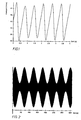
- the slippage between the weights and the body imbalance causes two sinusoidal unbalance signals (also the weights represent an imbalance in uneven distribution in the track) with different frequencies superimpose and cause a beating of the total imbalance signal (s. Figure 2).
- the cause is that the body imbalance rotates with the speed of the body and the imbalance of the balls due to the slippage has a slightly lower speed. Since the speed difference is very low, the beating is low frequency. In the example of a washing machine drum described below, it is approximately 60 seconds at a drum speed of 100 min -1 . At the minimum of beating, body imbalance and center of gravity are opposite each other and compensate each other.
- the non-sinusoidal speed curve by a targeted control or control can be achieved in which the drive positive or negative Acceleration pulses are impressed on the rotating system. These pulses will be delivered in an advantageous manner so that they act periodically on the system.
- targeted impulses can (even with bodies with horizontal axis of rotation) the duration of the Beating be influenced.
- FIG. 4 shows, on the basis of a schematic diagram, the parts which are essential for the invention in one embodiment such a washing machine. It has a tub (1) in which a drum (2) for Recording of laundry (3) is rotatably mounted. The drive of the drum (2) via a Motor (4), the power transmission via a V-belt (5). In this case, the speed of the engine in a known manner by one in the microprocessor control (6) of the washing machine integrated motor controller (6a) program and state-dependent.
- the tub (1) is suspended from springs (7) swinging in the housing (8) and is for Damping of these vibrations in the lower area by shock absorbers (9) over the Caseback (10) supported. For further damping of the vibrations are on the tub (1) Additional weights (11) arranged so that it passes through the critical Speed range does not hit the housing (8).
- a so-called ball balancer used in the drum cap (in the front drum area, not shown) and possibly in addition in the drum bottom (in the rear drum area, not shown) is as a balancing system a so-called ball balancer used.
- Balls (13) arranged as weights and can be released in the circumferential direction of the drum move.
- each raceway (12) must be in tightest packing in a predetermined angular range are filled with balls.
- a ball balancer on the drum cap is sufficient.
- Imbalance masses in the rear part of the drum (2) have only a small lever in the front Part of the drum (2) a large lever arm.
- the imbalance forces are from the drum (2) via the bearings (not shown) to the oscillating unit (tub (1), springs (7), Shock absorbers (9)) passed.
- the oscillating unit tub (1), springs (7), Shock absorbers (9)
- the total load of the vibrating unit rise. The load is therefore on the torque and thus on the product of imbalance mass, acceleration and lever arm due. It is therefore sufficient to use the imbalance masses with the large lever arm to balance the front drum half.
- the on the imbalances A and B or on the resulting total imbalance C acting centrifugal force Vectorially, the weight force overlaps so that the weight signal is unbalance dependent is exposed to periodic fluctuations, which is used to determine the imbalance Computer circuit (6b) can be used.
- the displacement sensor (14) can For example, from DE 195 22 393 known acceleration sensor for unbalance be used.
- another Computer circuit (6c) the imbalance by evaluating the fluctuations of a speed-dependent Signal (motor current, slip ...) or the speed itself (with a tachogenerator (15)).
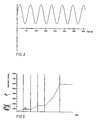
- An evaluation circuit (6d) integrated in the microprocessor control prepares this during the unbalance signal of the computer circuit (s) (6b, c) measured in the manner of the drum rotation, that only determines the envelope of the amount of imbalance signal and for further engine control is evaluated (see Figure 3).
- the inventive method for balancing the drum of a washing machine is based a speed-time profile shown in Figure 5 and operates as follows:
- the liquor is first pumped out of the tub (1). Then the spin start is started. It begins with the start of a measuring speed n Mess1 above the laundry application speed n A , but below the lowest resonance speed n R1 .
- n Mess1 a measuring speed above the laundry application speed n A , but below the lowest resonance speed n R1 .
- the speed for a short moment to a dewatering speed n E be increased, but the value must always be less than the lowest resonance speed n R1 .
- the speed is then lowered back to the measuring speed n Mess1 .
- the total imbalance C is sensed by the computer circuit (s) (6b, c). From the imbalance signal, the evaluation circuit evaluates the envelope of the signal amount to start the resonance passage in the beat minimum. For this purpose, the spin start is continued and the drum (2) accelerated to a speed above the resonance frequency n R1 .
- the beat frequency (see Figure 2) can be controlled by strong periodic acceleration pulses reduce, so that the duration until the passage through the beat minimum is shortened in time.
- the evaluation circuit (6d) then waits until the total imbalance falls below a threshold which is greater than the initially sensed minimum and is dependent on the first minimum, the total load, the type of wash and the run-up procedure. Thereafter, the actual spin start by the resonance speeds n Ri begins.
- a faster alternative is to calculate a start time for the spin start by the evaluation circuit (6d), which lies before the first beat minimum. This time depends on the operating point (load condition) of the washing machine and can be calculated by an algorithm from the envelope.
- the optimal point is in Range of the inflection point of the envelope, in any case before reaching the first Minimum.
- Another improvement is laundry imbalances in size and / or position to create consciously. Track the previously known methods for applying the laundry the goal is to position it as evenly as possible on the drum shell (2c). Because both the type of laundry as well as the amount of laundry by sensing different parameters (eg suction times, lye tank lowering, etc.) can be assumed to be known, can be adjusted by a speed pulse to the compensation capacity of the balls (13) generate corresponding laundry imbalance. In this case, the minimum beats almost the entire laundry imbalance compensated by the ball conglomerate. By the targeted positioning of the laundry imbalance to the ball conglomerate can be the time to Finding the minimum will be significantly shortened.
- these algorithms can also be repeated between the individual resonance regions n Ri . Due to the clever choice of the run-up profile, the balancing range n messi lying between individual resonant frequencies n Ri can likewise be used for the further imbalance minimization .
Landscapes
- Engineering & Computer Science (AREA)
- Textile Engineering (AREA)
- Control Of Washing Machine And Dryer (AREA)
- Testing Of Balance (AREA)
- Turbine Rotor Nozzle Sealing (AREA)
- Main Body Construction Of Washing Machines And Laundry Dryers (AREA)
Claims (8)
- Procédé pour équilibrer un corps qui est mis en rotation par un entraínement régulé, au moyen d'un dispositif d'équilibrage se composant d'au moins un chemin de roulement (12) en forme d'anneau circulaire, tournant avec le corps, disposé concentriquement par rapport à son axe de rotation, à l'intérieur duquel sont disposés des poids (13) librement mobiles, et au moyen d'un dispositif de détection de déséquilibre (6b, c) qui convertit les déviations dues au déséquilibre du système formé par le corps et le dispositif d'équilibrage pendant la rotation et/ou ses variations de vitesse de rotation dues au déséquilibre en un signal de déséquilibre, selon lequel, dans un premier pas de procédé de détection de déséquilibre, le système est mis en rotation à une vitesse de rotation inférieure à sa vitesse de rotation critique ou inférieure à la vitesse de rotation critique de son système de roulement et selon lequel le dispositif d'équilibrage est conçu de telle manière que les poids (13) sont entraínés par le(s) chemin(s) de roulement (12) à cette vitesse de rotation,
caractérisé par le fait qu'un circuit d'évaluation (6d) détermine la courbe enveloppe de la valeur du signal de déséquilibre et, au voisinage de son minimum ou si celle-ci est inférieure à une valeur limite, accélère le corps à une vitesse de rotation supérieure à sa vitesse de rotation critique ou à la vitesse de rotation critique de son système de roulement. - Procédé pour équilibrer un corps en rotation selon la revendication 1,
caractérisé par le fait que le circuit d'évaluation détermine, en tenant compte de paramètres de fonctionnement, une valeur de départ de l'accélération à une vitesse de rotation supérieure à la vitesse de rotation critique du corps ou de son système de roulement, la valeur se situant avant l'atteinte du premier minimum de la courbe enveloppe de la valeur du signal de déséquilibre. - Procédé pour équilibrer un corps en rotation selon la revendication 1 ou 2,
caractérisé par le fait que des moyens de réglage de la vitesse de rotation ou de régulation agissant sur l'entraínement délivrent pendant un tour complet du système au moins une impulsion d'accélération positive ou négative au système. - Procédé pour équilibrer un corps en rotation selon la revendication 4,
caractérisé par le fait que les impulsions d'accélération positives ou négatives agissent périodiquement sur le système. - Procédé pour équilibrer un corps en rotation autour d'un axe de rotation approximativement horizontal selon au moins l'une des revendications 1 à 4,
caractérisé par l'utilisation d'un moyen disposé sur le(s) chemin(s) de roulement (12) pour élever le frottement de roulement des poids ou la résistance à l'écoulement du ou des chemin(s) de roulement (12). - Procédé pour équilibrer un corps en rotation autour d'un axe de rotation approximativement horizontal selon la revendication 5,
caractérisé par le fait que le moyen pour élever la résistance à l'écoulement du ou des chemin(s) de roulement (12) est constitué d'un moyen d'amortissement visqueux (14) dont la viscosité est telle que les poids (13) sont entraínés dans la plage de vitesses de rotation dans laquelle la détection de déséquilibre est effectuée. - Procédé pour équilibrer le tambour (2) d'une machine à laver à tambour selon au moins l'une des revendications 1 à 6,
caractérisé par le fait que la détection de déséquilibre est effectuée au-dessus d'une vitesse de rotation à laquelle le linge est appliqué contre l'enveloppe du tambour (2c) par l'accélération centrifuge. - Procédé pour équilibrer un tambour (2) selon la revendication 7,
caractérisé par le fait que l'on génère un déséquilibre de linge défini par sa taille et/ou sa position.
Applications Claiming Priority (2)
| Application Number | Priority Date | Filing Date | Title |
|---|---|---|---|
| DE19952464 | 1999-10-29 | ||
| DE19952464A DE19952464C2 (de) | 1999-10-29 | 1999-10-29 | Verfahren zum Auswuchten eines rotierenden Körpers, der durch einen geregelten Antrieb in Rotation versetzt wird, und Verwendung des Verfahrens |
Publications (3)
| Publication Number | Publication Date |
|---|---|
| EP1096050A2 EP1096050A2 (fr) | 2001-05-02 |
| EP1096050A3 EP1096050A3 (fr) | 2002-08-14 |
| EP1096050B1 true EP1096050B1 (fr) | 2005-08-17 |
Family
ID=7927509
Family Applications (1)
| Application Number | Title | Priority Date | Filing Date |
|---|---|---|---|
| EP00122114A Expired - Lifetime EP1096050B1 (fr) | 1999-10-29 | 2000-10-12 | Procédé pour l'équilibrage de corps tournants |
Country Status (4)
| Country | Link |
|---|---|
| EP (1) | EP1096050B1 (fr) |
| AT (1) | ATE302300T1 (fr) |
| DE (2) | DE19952464C2 (fr) |
| ES (1) | ES2244383T3 (fr) |
Families Citing this family (14)
| Publication number | Priority date | Publication date | Assignee | Title |
|---|---|---|---|---|
| DE10202252C1 (de) * | 2002-01-21 | 2003-03-20 | Miele & Cie | Verfahren zum Betrieb einer Waschmaschine |
| DE10244426B4 (de) | 2002-09-24 | 2005-02-10 | Siemens Ag | Bearbeitungsmaschine |
| KR101085495B1 (ko) * | 2006-11-06 | 2011-11-23 | 삼성전자주식회사 | 드럼 세탁기의 터브 진동제어방법 |
| KR101267334B1 (ko) | 2006-11-06 | 2013-05-23 | 삼성전자주식회사 | 세탁기의 볼 밸런서 제어방법 |
| KR101428477B1 (ko) | 2007-01-24 | 2014-08-12 | 삼성전자 주식회사 | 세탁기 및 그 제어방법 |
| KR101287536B1 (ko) * | 2007-06-05 | 2013-07-18 | 삼성전자주식회사 | 세탁기 및 그 제어방법 |
| KR101407959B1 (ko) | 2008-01-22 | 2014-06-20 | 삼성전자주식회사 | 볼 밸런서를 구비한 드럼 세탁기 및 그 제어방법 |
| EP2470712B1 (fr) | 2009-08-27 | 2018-03-07 | LG Electronics Inc. | Procédé de commande d'un lave-linge |
| WO2011025317A1 (fr) * | 2009-08-27 | 2011-03-03 | Lg Electronics Inc. | Procédé de commande d'un lave-linge |
| US20120151694A1 (en) * | 2009-08-27 | 2012-06-21 | Jae Hyuk Jang | Control method of laundry machine |
| DE102010053104B4 (de) | 2010-12-01 | 2012-12-13 | Diehl Ako Stiftung & Co. Kg | Wäschebehandlungsvorrichtung und Verfahren zum Steuern des Betriebs einer Wäschebehandlungsvorrichtung |
| AU2013204355B2 (en) | 2012-12-21 | 2016-10-27 | Fisher & Paykel Appliances Limited | Improved laundry appliance |
| US9493897B2 (en) * | 2013-06-25 | 2016-11-15 | Whirlpool Corporation | Method of operation for a laundry treating appliance having a ball balance ring |
| EP3702509B1 (fr) * | 2019-02-28 | 2021-09-01 | BSH Hausgeräte GmbH | Appareil domestique comportant un dispositif d'équilibrage à billes et un contrôle de la viscosité des fluides |
Citations (1)
| Publication number | Priority date | Publication date | Assignee | Title |
|---|---|---|---|---|
| DE3421845A1 (de) * | 1984-06-13 | 1985-12-19 | Robert Bosch Gmbh, 7000 Stuttgart | Vorrichtung zum erfassen der unwucht eines rotierenden koerpers |
Family Cites Families (9)
| Publication number | Priority date | Publication date | Assignee | Title |
|---|---|---|---|---|
| DE3821239C2 (de) * | 1988-06-23 | 1996-10-24 | Dittel Walter Gmbh | Verfahren zum Auswuchten von rotierenden Teilen und Vorrichtung zur Durchführung des Verfahrens |
| CA2069120C (fr) * | 1992-05-21 | 2005-04-26 | Anton Gasafi | Methode et appareil de correction de balourd |
| DE19506471C2 (de) * | 1995-02-24 | 1999-10-21 | Roland Schuehle | Verfahren zur elektronischen Bestimmung und Kontrolle der Güte der Ausrichtung aneinandergekuppelter Wellen und Vorrichtung zu dessen Durchführung |
| DE19549526C2 (de) * | 1995-06-23 | 1999-02-11 | Miele & Cie | Verfahren zur Steuerung des Schleuderprozesses einer Waschmaschine |
| IT1289380B1 (it) * | 1996-05-30 | 1998-10-02 | Electrolux Zanussi Elettrodome | Lavabiancheria con procedimento perfezionato di bilanciamento dinamico |
| DE19718321C1 (de) * | 1997-04-30 | 1998-10-29 | Miele & Cie | Verfahren zum Auswuchten von rotierenden Körpern |
| DE19842610A1 (de) * | 1997-12-10 | 1999-07-01 | Miele & Cie | Verfahren zur Steuerung des Schleuderhochlaufs in einer Waschmaschine oder einem Waschtrockner |
| ES2186081T3 (es) * | 1997-12-20 | 2003-05-01 | Miele & Cie | Maquina lavadora de tambor o secadora de ropa y procedimiento para lavar y centrifugar la colada en una maquina lavadora o en una secadora de ropa. |
| DE19804080B4 (de) * | 1998-02-03 | 2005-07-21 | AEG Hausgeräte GmbH | Verfahren zum Umverteilen von in eine Trommel in einer Waschmaschine eingebrachter Wäsche |
-
1999
- 1999-10-29 DE DE19952464A patent/DE19952464C2/de not_active Expired - Fee Related
-
2000
- 2000-10-12 EP EP00122114A patent/EP1096050B1/fr not_active Expired - Lifetime
- 2000-10-12 ES ES00122114T patent/ES2244383T3/es not_active Expired - Lifetime
- 2000-10-12 DE DE50010961T patent/DE50010961D1/de not_active Expired - Lifetime
- 2000-10-12 AT AT00122114T patent/ATE302300T1/de not_active IP Right Cessation
Patent Citations (1)
| Publication number | Priority date | Publication date | Assignee | Title |
|---|---|---|---|---|
| DE3421845A1 (de) * | 1984-06-13 | 1985-12-19 | Robert Bosch Gmbh, 7000 Stuttgart | Vorrichtung zum erfassen der unwucht eines rotierenden koerpers |
Also Published As
| Publication number | Publication date |
|---|---|
| DE50010961D1 (de) | 2005-09-22 |
| DE19952464C2 (de) | 2002-05-08 |
| ES2244383T3 (es) | 2005-12-16 |
| ATE302300T1 (de) | 2005-09-15 |
| DE19952464A1 (de) | 2001-05-23 |
| EP1096050A3 (fr) | 2002-08-14 |
| EP1096050A2 (fr) | 2001-05-02 |
Similar Documents
| Publication | Publication Date | Title |
|---|---|---|
| EP1096050B1 (fr) | Procédé pour l'équilibrage de corps tournants | |
| EP2044254B1 (fr) | Procédé pour la commande du déroulement de l'essorage d'un lave-linge et lave-linge approprié pour l'exécution du procédé | |
| DE60116622T2 (de) | Vorauswuchten einer waschmaschine bei niedriger drehgeschwindigkeit | |
| EP2379786B1 (fr) | Procédé pour commander une fonction de répartition du linge dans un appareil ménager destiné à l'entretien du linge | |
| DE60113335T2 (de) | Verfahren und Vorrichtung zum Vorhersagen der Unwucht in einem Gerät | |
| DE602006000888T2 (de) | Methode und Vorrichtung zur Unwuchtüberwachung in einer horizontalachsigen Waschmaschine | |
| DE60110684T2 (de) | Verfahren und Vorrichtung zum Erfassen der Unwucht in einem Gerät | |
| DE10022609C2 (de) | Verfahren zur Begrenzung der Unwuchtwirkung einer Wascheinheit einer Waschmaschine und Vorrichtung zur Durchführung des Verfahrens | |
| WO2009068386A1 (fr) | Procédé et dispositif pour déterminer le régime optimal du tambour d'un dispositif de traitement du linge | |
| EP0750065B1 (fr) | Dispositif et procédé pour la détermination du balourd dans une machine à laver à tambour | |
| EP2412864A2 (fr) | Appareil de traitement du linge | |
| EP0878575B1 (fr) | Procédé pour équilibrer un corps tournant | |
| EP2010705A1 (fr) | Machine a laver et/ou seche-linge | |
| EP0924330B1 (fr) | Machine à laver à tambour ou sèche-linge et procédé pour laver et essorer du linge dans une machine à laver ou une machine à laver et à sécher | |
| DE102006017530A1 (de) | Maschine zum Waschen und/oder Trocknen von Wäsche sowie Verfahren zum Erfassen von Unwuchtparametern | |
| DE102012021747B4 (de) | Verfahren und Vorrichtung zum Erkennen einer Umwucht in einem Wäschebehandlungsgerät | |
| EP3114268B1 (fr) | Procédé de détermination d'un poids de chargement d'un système oscillant d'un appareil électroménager destiné à l'entretien d'articles de linge, et appareil électroménager | |
| EP0942196B1 (fr) | Dispositif pour équilibrer des corps rotatifs | |
| DE19842611C2 (de) | Waschmaschine oder Waschtrockner | |
| DE69513800T2 (de) | Verfahren und Vorrichtung zum Auswuchten in Waschmaschinen | |
| EP4127291A1 (fr) | Procédé permettant de faire fonctionner une machine à laver et machine à laver | |
| DE60014191T2 (de) | Sich drehende Maschinen mit einem Ungleichgewicht des Betriebes | |
| EP4127292B1 (fr) | Méthode de fonctionnement d'une machine à laver automatique et machine à laver automatique | |
| DE19842610A1 (de) | Verfahren zur Steuerung des Schleuderhochlaufs in einer Waschmaschine oder einem Waschtrockner | |
| DE102014001676A1 (de) | Wäschebehandlungsgerät mit Unwuchterfassungseinrichtung und Verfahren zum Erkennen einer Unwucht in einem Wäschebehandlungsgerät |
Legal Events
| Date | Code | Title | Description |
|---|---|---|---|
| PUAI | Public reference made under article 153(3) epc to a published international application that has entered the european phase |
Free format text: ORIGINAL CODE: 0009012 |
|
| AK | Designated contracting states |
Kind code of ref document: A2 Designated state(s): AT BE CH CY DE DK ES FI FR GB GR IE IT LI LU MC NL PT SE |
|
| AX | Request for extension of the european patent |
Free format text: AL;LT;LV;MK;RO;SI |
|
| PUAL | Search report despatched |
Free format text: ORIGINAL CODE: 0009013 |
|
| AK | Designated contracting states |
Kind code of ref document: A3 Designated state(s): AT BE CH CY DE DK ES FI FR GB GR IE IT LI LU MC NL PT SE |
|
| AX | Request for extension of the european patent |
Free format text: AL;LT;LV;MK;RO;SI |
|
| 17P | Request for examination filed |
Effective date: 20030116 |
|
| AKX | Designation fees paid |
Designated state(s): AT BE CH CY DE DK ES FI FR GB GR IE IT LI LU MC NL PT SE |
|
| RAP1 | Party data changed (applicant data changed or rights of an application transferred) |
Owner name: MIELE & CIE. KG |
|
| 17Q | First examination report despatched |
Effective date: 20041011 |
|
| GRAP | Despatch of communication of intention to grant a patent |
Free format text: ORIGINAL CODE: EPIDOSNIGR1 |
|
| GRAS | Grant fee paid |
Free format text: ORIGINAL CODE: EPIDOSNIGR3 |
|
| GRAA | (expected) grant |
Free format text: ORIGINAL CODE: 0009210 |
|
| AK | Designated contracting states |
Kind code of ref document: B1 Designated state(s): AT BE CH CY DE DK ES FI FR GB GR IE IT LI LU MC NL PT SE |
|
| PG25 | Lapsed in a contracting state [announced via postgrant information from national office to epo] |
Ref country code: IE Free format text: LAPSE BECAUSE OF FAILURE TO SUBMIT A TRANSLATION OF THE DESCRIPTION OR TO PAY THE FEE WITHIN THE PRESCRIBED TIME-LIMIT Effective date: 20050817 Ref country code: FI Free format text: LAPSE BECAUSE OF FAILURE TO SUBMIT A TRANSLATION OF THE DESCRIPTION OR TO PAY THE FEE WITHIN THE PRESCRIBED TIME-LIMIT Effective date: 20050817 |
|
| REG | Reference to a national code |
Ref country code: GB Ref legal event code: FG4D Free format text: NOT ENGLISH |
|
| RIN1 | Information on inventor provided before grant (corrected) |
Inventor name: KUKA, THORSTEN Inventor name: DYBALLA, CHRISTIAN, DR. Inventor name: HERDEN, RUDOLF Inventor name: GROSSE HUENDFELD, MAX Inventor name: HAPKE, ARMIN Inventor name: HAMBROCK, JUERGEN Inventor name: KAUFMANN, REINHARD Inventor name: MUELLER, HELGE |
|
| REG | Reference to a national code |
Ref country code: CH Ref legal event code: EP |
|
| REG | Reference to a national code |
Ref country code: CH Ref legal event code: NV Representative=s name: PA ALDO ROEMPLER |
|
| REG | Reference to a national code |
Ref country code: IE Ref legal event code: FG4D Free format text: LANGUAGE OF EP DOCUMENT: GERMAN |
|
| REF | Corresponds to: |
Ref document number: 50010961 Country of ref document: DE Date of ref document: 20050922 Kind code of ref document: P |
|
| REG | Reference to a national code |
Ref country code: SE Ref legal event code: TRGR |
|
| PG25 | Lapsed in a contracting state [announced via postgrant information from national office to epo] |
Ref country code: CY Free format text: LAPSE BECAUSE OF FAILURE TO SUBMIT A TRANSLATION OF THE DESCRIPTION OR TO PAY THE FEE WITHIN THE PRESCRIBED TIME-LIMIT Effective date: 20051012 |
|
| GBT | Gb: translation of ep patent filed (gb section 77(6)(a)/1977) |
Effective date: 20051003 |
|
| PG25 | Lapsed in a contracting state [announced via postgrant information from national office to epo] |
Ref country code: LU Free format text: LAPSE BECAUSE OF NON-PAYMENT OF DUE FEES Effective date: 20051031 Ref country code: BE Free format text: LAPSE BECAUSE OF NON-PAYMENT OF DUE FEES Effective date: 20051031 Ref country code: MC Free format text: LAPSE BECAUSE OF NON-PAYMENT OF DUE FEES Effective date: 20051031 |
|
| PG25 | Lapsed in a contracting state [announced via postgrant information from national office to epo] |
Ref country code: GR Free format text: LAPSE BECAUSE OF FAILURE TO SUBMIT A TRANSLATION OF THE DESCRIPTION OR TO PAY THE FEE WITHIN THE PRESCRIBED TIME-LIMIT Effective date: 20051117 Ref country code: DK Free format text: LAPSE BECAUSE OF FAILURE TO SUBMIT A TRANSLATION OF THE DESCRIPTION OR TO PAY THE FEE WITHIN THE PRESCRIBED TIME-LIMIT Effective date: 20051117 |
|
| REG | Reference to a national code |
Ref country code: ES Ref legal event code: FG2A Ref document number: 2244383 Country of ref document: ES Kind code of ref document: T3 |
|
| PG25 | Lapsed in a contracting state [announced via postgrant information from national office to epo] |
Ref country code: PT Free format text: LAPSE BECAUSE OF FAILURE TO SUBMIT A TRANSLATION OF THE DESCRIPTION OR TO PAY THE FEE WITHIN THE PRESCRIBED TIME-LIMIT Effective date: 20060117 |
|
| REG | Reference to a national code |
Ref country code: IE Ref legal event code: FD4D |
|
| ET | Fr: translation filed | ||
| PLBE | No opposition filed within time limit |
Free format text: ORIGINAL CODE: 0009261 |
|
| STAA | Information on the status of an ep patent application or granted ep patent |
Free format text: STATUS: NO OPPOSITION FILED WITHIN TIME LIMIT |
|
| 26N | No opposition filed |
Effective date: 20060518 |
|
| REG | Reference to a national code |
Ref country code: GB Ref legal event code: 746 Effective date: 20061020 |
|
| BERE | Be: lapsed |
Owner name: MIELE & CIE. K.G. Effective date: 20051031 |
|
| REG | Reference to a national code |
Ref country code: CH Ref legal event code: PCAR Free format text: ALDO ROEMPLER PATENTANWALT;BRENDENWEG 11 POSTFACH 154;9424 RHEINECK (CH) |
|
| PGFP | Annual fee paid to national office [announced via postgrant information from national office to epo] |
Ref country code: NL Payment date: 20081023 Year of fee payment: 9 |
|
| PGFP | Annual fee paid to national office [announced via postgrant information from national office to epo] |
Ref country code: CH Payment date: 20081027 Year of fee payment: 9 |
|
| PGFP | Annual fee paid to national office [announced via postgrant information from national office to epo] |
Ref country code: AT Payment date: 20081023 Year of fee payment: 9 |
|
| PGFP | Annual fee paid to national office [announced via postgrant information from national office to epo] |
Ref country code: SE Payment date: 20081027 Year of fee payment: 9 |
|
| REG | Reference to a national code |
Ref country code: NL Ref legal event code: V1 Effective date: 20100501 |
|
| REG | Reference to a national code |
Ref country code: CH Ref legal event code: PL |
|
| EUG | Se: european patent has lapsed | ||
| PG25 | Lapsed in a contracting state [announced via postgrant information from national office to epo] |
Ref country code: NL Free format text: LAPSE BECAUSE OF NON-PAYMENT OF DUE FEES Effective date: 20100501 |
|
| PG25 | Lapsed in a contracting state [announced via postgrant information from national office to epo] |
Ref country code: AT Free format text: LAPSE BECAUSE OF NON-PAYMENT OF DUE FEES Effective date: 20091012 |
|
| PG25 | Lapsed in a contracting state [announced via postgrant information from national office to epo] |
Ref country code: LI Free format text: LAPSE BECAUSE OF NON-PAYMENT OF DUE FEES Effective date: 20091031 Ref country code: CH Free format text: LAPSE BECAUSE OF NON-PAYMENT OF DUE FEES Effective date: 20091031 |
|
| PG25 | Lapsed in a contracting state [announced via postgrant information from national office to epo] |
Ref country code: SE Free format text: LAPSE BECAUSE OF NON-PAYMENT OF DUE FEES Effective date: 20091013 |
|
| PGFP | Annual fee paid to national office [announced via postgrant information from national office to epo] |
Ref country code: FR Payment date: 20141021 Year of fee payment: 15 Ref country code: ES Payment date: 20141024 Year of fee payment: 15 Ref country code: DE Payment date: 20141031 Year of fee payment: 15 Ref country code: GB Payment date: 20141024 Year of fee payment: 15 |
|
| PGFP | Annual fee paid to national office [announced via postgrant information from national office to epo] |
Ref country code: IT Payment date: 20141029 Year of fee payment: 15 |
|
| REG | Reference to a national code |
Ref country code: DE Ref legal event code: R119 Ref document number: 50010961 Country of ref document: DE |
|
| GBPC | Gb: european patent ceased through non-payment of renewal fee |
Effective date: 20151012 |
|
| PG25 | Lapsed in a contracting state [announced via postgrant information from national office to epo] |
Ref country code: DE Free format text: LAPSE BECAUSE OF NON-PAYMENT OF DUE FEES Effective date: 20160503 Ref country code: IT Free format text: LAPSE BECAUSE OF NON-PAYMENT OF DUE FEES Effective date: 20151012 Ref country code: GB Free format text: LAPSE BECAUSE OF NON-PAYMENT OF DUE FEES Effective date: 20151012 |
|
| REG | Reference to a national code |
Ref country code: FR Ref legal event code: ST Effective date: 20160630 |
|
| PG25 | Lapsed in a contracting state [announced via postgrant information from national office to epo] |
Ref country code: FR Free format text: LAPSE BECAUSE OF NON-PAYMENT OF DUE FEES Effective date: 20151102 |
|
| REG | Reference to a national code |
Ref country code: ES Ref legal event code: FD2A Effective date: 20161129 |
|
| PG25 | Lapsed in a contracting state [announced via postgrant information from national office to epo] |
Ref country code: ES Free format text: LAPSE BECAUSE OF NON-PAYMENT OF DUE FEES Effective date: 20151013 |