EP1096126A2 - Gerät und Methode zur Auspuffheizung für einen Verbrennungsmotor - Google Patents
Gerät und Methode zur Auspuffheizung für einen Verbrennungsmotor Download PDFInfo
- Publication number
- EP1096126A2 EP1096126A2 EP00123124A EP00123124A EP1096126A2 EP 1096126 A2 EP1096126 A2 EP 1096126A2 EP 00123124 A EP00123124 A EP 00123124A EP 00123124 A EP00123124 A EP 00123124A EP 1096126 A2 EP1096126 A2 EP 1096126A2
- Authority
- EP
- European Patent Office
- Prior art keywords
- exhaust gas
- exhaust
- gas temperature
- temperature increase
- injection
- Prior art date
- Legal status (The legal status is an assumption and is not a legal conclusion. Google has not performed a legal analysis and makes no representation as to the accuracy of the status listed.)
- Granted
Links
- 238000002485 combustion reaction Methods 0.000 title claims abstract description 68
- 238000000034 method Methods 0.000 title claims description 11
- 238000002347 injection Methods 0.000 claims abstract description 126
- 239000007924 injection Substances 0.000 claims abstract description 126
- 230000005856 abnormality Effects 0.000 claims abstract description 72
- 239000000446 fuel Substances 0.000 claims description 69
- 238000011144 upstream manufacturing Methods 0.000 claims description 8
- 230000001965 increasing effect Effects 0.000 claims description 7
- 238000012544 monitoring process Methods 0.000 claims description 4
- 239000007789 gas Substances 0.000 description 225
- 239000003054 catalyst Substances 0.000 description 17
- 230000006870 function Effects 0.000 description 12
- 230000002159 abnormal effect Effects 0.000 description 8
- 230000006866 deterioration Effects 0.000 description 6
- 238000001514 detection method Methods 0.000 description 5
- 230000000694 effects Effects 0.000 description 5
- 238000005516 engineering process Methods 0.000 description 5
- 230000003197 catalytic effect Effects 0.000 description 4
- 238000010586 diagram Methods 0.000 description 4
- 230000008901 benefit Effects 0.000 description 3
- 230000007423 decrease Effects 0.000 description 3
- 230000003647 oxidation Effects 0.000 description 3
- 238000007254 oxidation reaction Methods 0.000 description 3
- 238000012545 processing Methods 0.000 description 3
- 238000010276 construction Methods 0.000 description 2
- 238000002474 experimental method Methods 0.000 description 2
- 238000004519 manufacturing process Methods 0.000 description 2
- 230000007246 mechanism Effects 0.000 description 2
- 230000008569 process Effects 0.000 description 2
- 230000009467 reduction Effects 0.000 description 2
- 238000011160 research Methods 0.000 description 2
- -1 that is Substances 0.000 description 2
- 230000002411 adverse Effects 0.000 description 1
- 230000002457 bidirectional effect Effects 0.000 description 1
- 239000000567 combustion gas Substances 0.000 description 1
- 238000004891 communication Methods 0.000 description 1
- 230000007547 defect Effects 0.000 description 1
- 238000013461 design Methods 0.000 description 1
- 238000001914 filtration Methods 0.000 description 1
- 238000009499 grossing Methods 0.000 description 1
- 230000007257 malfunction Effects 0.000 description 1
- 239000000203 mixture Substances 0.000 description 1
- 238000012986 modification Methods 0.000 description 1
- 230000004048 modification Effects 0.000 description 1
- 238000013021 overheating Methods 0.000 description 1
- 230000002195 synergetic effect Effects 0.000 description 1
- 238000012795 verification Methods 0.000 description 1
Images


Classifications
-
- F—MECHANICAL ENGINEERING; LIGHTING; HEATING; WEAPONS; BLASTING
- F02—COMBUSTION ENGINES; HOT-GAS OR COMBUSTION-PRODUCT ENGINE PLANTS
- F02D—CONTROLLING COMBUSTION ENGINES
- F02D41/00—Electrical control of supply of combustible mixture or its constituents
- F02D41/30—Controlling fuel injection
- F02D41/38—Controlling fuel injection of the high pressure type
- F02D41/40—Controlling fuel injection of the high pressure type with means for controlling injection timing or duration
- F02D41/402—Multiple injections
- F02D41/405—Multiple injections with post injections
-
- F—MECHANICAL ENGINEERING; LIGHTING; HEATING; WEAPONS; BLASTING
- F02—COMBUSTION ENGINES; HOT-GAS OR COMBUSTION-PRODUCT ENGINE PLANTS
- F02D—CONTROLLING COMBUSTION ENGINES
- F02D41/00—Electrical control of supply of combustible mixture or its constituents
- F02D41/02—Circuit arrangements for generating control signals
- F02D41/021—Introducing corrections for particular conditions exterior to the engine
- F02D41/0235—Introducing corrections for particular conditions exterior to the engine in relation with the state of the exhaust gas treating apparatus
- F02D41/024—Introducing corrections for particular conditions exterior to the engine in relation with the state of the exhaust gas treating apparatus to increase temperature of the exhaust gas treating apparatus
-
- F—MECHANICAL ENGINEERING; LIGHTING; HEATING; WEAPONS; BLASTING
- F02—COMBUSTION ENGINES; HOT-GAS OR COMBUSTION-PRODUCT ENGINE PLANTS
- F02D—CONTROLLING COMBUSTION ENGINES
- F02D41/00—Electrical control of supply of combustible mixture or its constituents
- F02D41/22—Safety or indicating devices for abnormal conditions
- F02D41/221—Safety or indicating devices for abnormal conditions relating to the failure of actuators or electrically driven elements
-
- F—MECHANICAL ENGINEERING; LIGHTING; HEATING; WEAPONS; BLASTING
- F02—COMBUSTION ENGINES; HOT-GAS OR COMBUSTION-PRODUCT ENGINE PLANTS
- F02D—CONTROLLING COMBUSTION ENGINES
- F02D9/00—Controlling engines by throttling air or fuel-and-air induction conduits or exhaust conduits
- F02D9/04—Controlling engines by throttling air or fuel-and-air induction conduits or exhaust conduits concerning exhaust conduits
-
- Y—GENERAL TAGGING OF NEW TECHNOLOGICAL DEVELOPMENTS; GENERAL TAGGING OF CROSS-SECTIONAL TECHNOLOGIES SPANNING OVER SEVERAL SECTIONS OF THE IPC; TECHNICAL SUBJECTS COVERED BY FORMER USPC CROSS-REFERENCE ART COLLECTIONS [XRACs] AND DIGESTS
- Y02—TECHNOLOGIES OR APPLICATIONS FOR MITIGATION OR ADAPTATION AGAINST CLIMATE CHANGE
- Y02T—CLIMATE CHANGE MITIGATION TECHNOLOGIES RELATED TO TRANSPORTATION
- Y02T10/00—Road transport of goods or passengers
- Y02T10/10—Internal combustion engine [ICE] based vehicles
- Y02T10/12—Improving ICE efficiencies
-
- Y—GENERAL TAGGING OF NEW TECHNOLOGICAL DEVELOPMENTS; GENERAL TAGGING OF CROSS-SECTIONAL TECHNOLOGIES SPANNING OVER SEVERAL SECTIONS OF THE IPC; TECHNICAL SUBJECTS COVERED BY FORMER USPC CROSS-REFERENCE ART COLLECTIONS [XRACs] AND DIGESTS
- Y02—TECHNOLOGIES OR APPLICATIONS FOR MITIGATION OR ADAPTATION AGAINST CLIMATE CHANGE
- Y02T—CLIMATE CHANGE MITIGATION TECHNOLOGIES RELATED TO TRANSPORTATION
- Y02T10/00—Road transport of goods or passengers
- Y02T10/10—Internal combustion engine [ICE] based vehicles
- Y02T10/40—Engine management systems
Definitions
- the present invention relates to an exhaust temperature raising apparatus and method for an internal combustion engine.
- Diesel engines produce large amounts of unburned HCs during low-load engine operations, and particularly during a warm-up operation, since the combustion chamber temperature is low during such operations.
- the pressure in the exhaust passage that is, the back pressure
- the exhaust gas temperature is unlikely to decrease, so that exhaust gas in the exhaust passage remains in a high temperature state.
- the exhaust gas flow rate decreases, so that high-temperature exhaust gas resides or dwells in a portion of the exhaust passage upstream of the exhaust control valve. While exhaust gas resides in this fashion, the exhaust gas is in a high-temperature state.
- unburned HCs among the exhaust gas components are oxidized, and the amount of unburned HCs contained in exhaust gas emitted into the atmosphere is reduced.
- an emission control catalyst is disposed in an engine exhaust passage. However, unless activated, the catalyst is unable to sufficiently control emission, that is, unable to lessen unburned HCs.
- main injection that is, fuel injection for producing the engine output
- sub-injection that is, subsidiary fuel injection after the main injection
- main combustion unburned HCs produced by the combustion attributed to the main injection
- sub-combustion the combustion attributed to the sub-injection
- the amount of unburned HCs itself decreases to a considerably low level.
- unburned HCs produced by the main combustion burn together with the sub-injection fuel, the amount of combustion increases. As a result, the exhaust gas temperature rises so that a high catalyst temperature is achieved. Thus, the amount of unburned HCs is reduced.
- the present inventors through experiments and researches, conceived of performing the main fuel injection in an excess-air condition, and after the main fuel injection, the sub-injection is performed to increase the amount of combustion, and an exhaust control valve provided in an exhaust passage is substantially completely closed.
- Whether unburned HCs have been normally lessened is determined based on detection values provided by various sensors, for example, an exhaust gas temperature sensor, a back pressure sensor, etc. It is conceivable that a failure in any one of the sensors can adversely affect the exhaust gas temperature. If such a sensor fails, the exhaust gas temperature cannot be monitored, so that the exhaust gas temperature control becomes impossible. As a result, the exhaust gas temperature does not remain in a temperature range of a target level (hereinafter, referred to as "target exhaust gas temperature”), so that production of unburned HCs may not be curbed.
- target exhaust gas temperature a target level
- the target exhaust gas temperature refers to an exhaust gas temperature which is sufficiently high to promote oxidation of unburned HCs, that is, generally-termed post-combustion, and which is not excessively high and therefore, if a catalyst is provided in an exhaust passage, will not cause heat deterioration of the catalyst.
- a sufficient amount of fuel may not be injected, and therefore the exhaust gas temperature may not reach the target exhaust gas temperature, or the amount of fuel injected may be excessively large, and therefore the exhaust gas temperature may exceed the target exhaust gas temperature.
- ECU engine control unit
- an object of the invention to provide an internal combustion engine exhaust temperature raising apparatus and method capable of detecting an abnormality in sensors, fuel injection valves, or the like during an early period and therefore capable of preventing an increase in the amount of unburned HCs in exhaust gas and, if a catalyst is provided in the exhaust passage, preventing heat deterioration of the catalyst.
- an exhaust temperature raising apparatus for an internal combustion engine includes an exhaust throttle valve that is provided in an exhaust passage of the internal combustion engine and that adjusts an amount of an exhaust gas flowing in the exhaust passage based on an amount of throttling by the exhaust throttle valve, a fuel injection valve that performs a main injection that is a fuel injection for producing an engine output and a sub-injection that is a subsidiary fuel injection after performance of the main injection, directly into a cylinder, exhaust gas temperature increase means for, during an engine operation during which a need to lessen an unburned fuel component contained in the exhaust gas is high, performing and controlling exhaust throttling by the exhaust throttle valve and performing and controlling an exhaust gas temperature increase through combustion attributed to the main injection performed in an excess-air condition by the fuel injection valve and combustion attributed to the sub-injection, exhaust gas temperature increase monitor means for monitoring a state of temperature increase of the exhaust gas caused by performance of the exhaust gas temperature increase means, monitor means abnormality determination means for determining whether the exhaust gas temperature increase monitor means has
- Examples of the aforementioned "an engine operation during which a need to lessen an unburned fuel component contained in the exhaust gas is high" include a low-speed and low-load operation of the engine and, more particularly, a warm-up operation of the engine.
- performing and controlling exhaust throttling by the exhaust throttle valve regarding the exhaust gas temperature increase means refers to closing the exhaust throttle valve to such a degree that an unburned fuel component, for example, unburned HCs, can be effectively lessened in conjunction with performance of combustion based on the main injection and the sub-injection; for example, it refers to closing the exhaust throttle valve to a completely closed state or a nearly completely closed state.
- the “exhaust gas temperature increase means” includes the exhaust throttle valve, the fuel injection valve, and an ECU that controls the operation of the exhaust throttle valve and the operation of the fuel injection valve.
- the “exhaust gas temperature increase monitor means” includes at least one sensor, such as a temperature sensor.
- the “monitor means abnormality determination means” and the “exhaust gas temperature increase stop means” includes and ECU.
- exhaust gas temperature increase means when the exhaust gas temperature increase means is operated, exhaust gas temperature increases due to combustion attributed to the main injection in an excess-air condition and combustion attributed to the sub-injection. Therefore, exhaust gas discharged from the cylinder of the internal combustion engine has an increased temperature. Furthermore, a high-temperature state of exhaust gas is maintained in the exhaust passage by exhaust throttling. Therefore, the oxidation of unburned HCs is promoted in the exhaust passage, so that the amount of unburned HCs can be reduced.
- the invention further achieves the following advantage. If, during the exhaust temperature raising control by the exhaust gas temperature increase means, it is determined by the monitor means abnormality determination means that the exhaust gas temperature increase monitor means is in a state in which the means cannot carry out the expected function thereof due to a failure or the like of the means (an abnormal state), the exhaust gas temperature increase stop means stops the operation of the exhaust gas temperature increase means. Therefore, the exhaust temperature raising control by the exhaust gas temperature increase means is stopped.
- the apparatus is able to prevent an unexpected increase in the amount of unburned HCs and, if a catalyst is provided in the exhaust passage, prevent heat deterioration of the catalyst caused by an abnormal exhaust temperature increase.
- an exhaust temperature raising apparatus for an internal combustion engine includes an exhaust throttle valve that is provided in an exhaust passage of the internal combustion engine and that adjusts an amount of an exhaust gas flowing in the exhaust passage based on an amount of throttling of the exhaust throttle valve; a fuel injection valve that performs a main injection that is a fuel injection for producing an engine output and a sub-injection that is a subsidiary fuel injection after performance of the main injection, directly into a cylinder, exhaust gas temperature increase means for, during an engine operation during which a need to lessen an unburned fuel component contained in the exhaust gas is high, performing and controlling exhaust throttling by the exhaust throttle valve and performing and controlling an exhaust gas temperature increase through combustion attributed to the main injection performed in an excess-air condition by the fuel injection valve and combustion attributed to the sub-injection, exhaust gas temperature increase monitor means for monitoring a state of temperature increase of the exhaust gas caused by performance of the exhaust gas temperature increase means, exhaust gas temperature increase abnormality determination means for determining whether there is an abnormality regarding
- the “exhaust gas temperature increase abnormality determination means” includes an ECU.
- the temperature of exhaust gas is increased by performance of the exhaust gas temperature increase means, so that the amount of unburned HCs can be reduced.
- the exhaust temperature raising apparatus also achieves the following advantages.
- the exhaust gas temperature increase abnormality determination means in this aspect of the invention determines that there is an abnormality regarding the state of exhaust gas temperature increase, and then the exhaust gas temperature increase stop means stops the operation of the exhaust gas temperature increase means. At the time of the stop, therefore, undesired excessive combustion in the cylinder discontinues.
- the apparatus is able to prevent an increase in the amount of HCs caused by undesired excessive combustion and, if a catalyst is provided in the exhaust passage, prevent heat deterioration of the catalyst.
- the exhaust gas temperature increase abnormality determination means determines that there is an abnormality regarding the state of temperature increase of the exhaust gas, it may be determined that the exhaust gas temperature increase means has an abnormality, and the operation of the exhaust gas temperature increase means may be stopped.
- the exhaust gas temperature increase monitor means may include an exhaust gas temperature sensor provided at a suitable location in the exhaust passage, and the exhaust gas temperature increase monitor means may monitor the state of temperature increase of the exhaust gas based on an exhaust gas temperature detected by the exhaust gas temperature sensor.
- the suitable location at which the exhaust gas temperature sensor is provided may be, for example, a location in the exhaust passage upstream of the exhaust throttle valve.
- the exhaust gas temperature increase monitor means may include a back pressure sensor provided at a location in the exhaust passage upstream of a location of the exhaust throttle valve, and the exhaust gas temperature increase monitor means may monitor the state of temperature increase of the exhaust gas based on a back pressure detected by the back pressure sensor.
- the back pressure sensor is included in the exhaust gas temperature increase monitor means because changes in the back pressure are in association with changes in the exhaust gas temperature.
- the exhaust gas temperature increase monitor means may include a back pressure sensor and an exhaust gas temperature sensor that are provided in a portion of the exhaust passage upstream of the exhaust throttle valve.
- the monitor means abnormality determination means may determine that there is no abnormality regarding the state of temperature increase of the exhaust gas.
- the target range of the back pressure refers to values of back pressure that are included within such a range that the exhaust gas temperature is likely to reach the target exhaust gas temperature during the exhaust temperature raising control.
- the back pressure has a great effect on the exhaust gas temperature, so that if a certain exhaust gas temperature can be secured by adjustment of the back pressure, it becomes easier to bring the exhaust gas temperature to the target exhaust gas temperature.
- the exhaust gas temperature increase stop means may stop the operation of the exhaust gas temperature increase means by opening the exhaust throttle valve and stopping performance of the sub-injection.
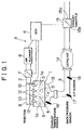
- FIGURES 1 and 2 A first embodiment of the invention will be described with reference to FIGURES 1 and 2.
- FIGURE 1 is a schematic illustration of a lean-burn engine A (hereinafter, referred to as "engine A”) that includes an internal combustion engine exhaust temperature raising apparatus according to the invention.
- the engine A is a four-cylinder four-stroke engine having a cylinder block 1 in which four cylinders 1a are formed. Each cylinder 1a has a combustion chamber (not shown) to which an intake passage 2 and an exhaust passage 3 are connected in communication.
- the operation of the engine A is controlled by an ECU 4 that is an engine control unit.
- the cylinder block 1 is provided with ignition plugs 5 corresponding to the individual cylinders 1a.
- Each ignition plug 5 performs ignition based on an ignition signal distributed by a distributor (not shown).
- the distributor distributes a high voltage outputted from an igniter to each ignition plug 5 synchronously with the crank angle of the engine A.
- the distributor and the igniter are not shown in the drawings.
- the intake passage 2 is provided with an air cleaner 6 for filtering air from outside, a throttle valve 7 for adjusting the amount of intake air flowing in the intake passage 2, a surge tank 8 for smoothing pulsating flows of intake air, and an intake manifold 10 provided as an intake air distribution pipe, which are disposed in that order in a direction from an upstream side toward the cylinder block 1.
- an air cleaner 6 for filtering air from outside
- a throttle valve 7 for adjusting the amount of intake air flowing in the intake passage 2
- a surge tank 8 for smoothing pulsating flows of intake air
- an intake manifold 10 provided as an intake air distribution pipe, which are disposed in that order in a direction from an upstream side toward the cylinder block 1.
- Each cylinder 1a is provided with an injector 12, that is, a fuel injection valve that performs the main injection, that is, fuel injection for producing engine output, and the sub-injection, that is, subsidiary fuel injection that follows the main injection, into the cylinder 1a.
- injector 12 that is, a fuel injection valve that performs the main injection, that is, fuel injection for producing engine output, and the sub-injection, that is, subsidiary fuel injection that follows the main injection, into the cylinder 1a.
- each combustion chamber a mixture of intake air introduced from the intake passage 2 and fuel injected from the injector 12 burns upon ignition by the ignition plug 5, so that the driving force for the engine A is produced. Combustion gas produced in each combustion chamber is emitted into the atmosphere via the exhaust passage 3.
- the exhaust passage 3 is provided with an exhaust manifold 13, that is, an exhaust collection pipe, a catalytic converter 14 as an emission control device, and an exhaust throttle valve 15 disposed downstream of the catalytic converter 14 for adjusting the back pressure in the exhaust passage 3 by adjusting the amount of exhaust gas flowing in the exhaust passage 3 based on the amount of the throttle aperture of the valve, which are disposed in that order in a direction from the cylinder block 1 toward a downstream side.
- an exhaust manifold 13 that is, an exhaust collection pipe, a catalytic converter 14 as an emission control device, and an exhaust throttle valve 15 disposed downstream of the catalytic converter 14 for adjusting the back pressure in the exhaust passage 3 by adjusting the amount of exhaust gas flowing in the exhaust passage 3 based on the amount of the throttle aperture of the valve, which are disposed in that order in a direction from the cylinder block 1 toward a downstream side.
- the exhaust manifold 13 has an exhaust air temperature sensor 16 for detecting the exhaust gas temperature.
- An internal space of the catalytic converter 14 is filled with an emission control catalyst (not shown), whereby exhaust gas flowing in the exhaust passage 3 is controlled or cleaned before being emitted into the atmosphere.
- the exhaust throttle valve 15 is formed by a valve body 15a that actually performs exhaust throttling, and a valve body opening-closing mechanism 15b that opens and closes the valve body 15a.
- the valve body opening-closing mechanism 15b is electrically connected to the ECU 4, and opens or closes the valve body 15a when necessary, based on an execution instruction from the ECU 4.
- a portion of the exhaust passage 3 between the exhaust manifold 13 and the catalytic converter 14, that is, a portion upstream of the exhaust throttle valve 15, is provided with a back pressure sensor 17 and an air-fuel-ratio sensor 18 disposed downstream of the back pressure sensor 17.
- the ECU 4 is a digital computer that, although not shown, is formed by a central processing control unit (CPU), a read-only memory (ROM), a random access memory (RAM), an input interface circuit, an output interface circuit, etc., which are interconnected by a bidirectional bus, as well known.
- CPU central processing control unit
- ROM read-only memory
- RAM random access memory
- input interface circuit an output interface circuit, etc., which are interconnected by a bidirectional bus, as well known.
- the input interface circuit is connected to the sensors 16, 17, 18 and other sensors (not shown) via electric wiring.
- the output interface is connected, via electric wiring, to appliances and devices that control the operation of the engine, such as the throttle valve 7, the injectors 12, the exhaust throttle valve 15, etc.
- the various sensors output electric signals corresponding to values detected thereby, to the ECU 4. Based on the output signal values from the sensors, the ECU 4 comprehensively determines an operation state of the cylinder block 1. In accordance with needs, the ECU 4 controls the throttle valve 7, the ignition plugs 5, the injectors 12, the exhaust throttle valve 15, etc.
- the injectors 12 function as main injection execution means for injecting fuel into the cylinders in an excess-air condition so as to produce an engine output, and function as a sub-injection execution means for injecting fuel subsidiarily to the fuel injected by execution of the main injection.
- the sub-injection in addition the main injection achieves additional fuel combustion to heat engine exhaust gas to a high temperature.
- exhaust throttling is performed by the exhaust throttle valve 15.
- the temperature increasing effect can be explained in a description of a result of control of the injectors 12 and the exhaust throttle valve 15 under the control of the ECU 4. That is, during operation of the engine A, the ECU 4 raises the exhaust gas temperature by executing and controlling the combustion attributed to the main injection in the excess-air condition for producing the engine output and to the sub-injection, that is, subsidiary fuel injection performed after execution of the main injection, and by executing and controlling the exhaust throttling using the exhaust throttle valve 15. Therefore, the ECU 4, and the injectors 12 and the exhaust throttle valve 15 operated under the control of the ECU 4 may be regarded as exhaust gas temperature raising means.
- the exhaust air temperature sensor 16 and the back pressure sensor 17 monitor exhaust gas temperature increases achieved by the ECU 4, that is, the exhaust gas temperature raising means. That is, based on the exhaust gas temperature and the back pressure indicated by the sensors, exhaust gas temperature increase is monitored. Thus, the two sensors are referred to as exhaust gas temperature increase monitor means.
- the back pressure sensor 17 is included in the exhaust gas temperature increase monitor means because changes in the back pressure are in direct association with changes in exhaust gas temperature.
- the ECU 4 also functions as monitor means abnormality determination means for determining whether an abnormality is present in the sensors 16, 17, that is, the exhaust gas temperature increase monitor means. If the ECU 4, as the monitor means abnormality determination means, determines that an abnormality is present in the exhaust air temperature sensor 16 or the back pressure sensor 17, the ECU 4 stops the function of the exhaust gas temperature increase means provided in the ECU 4. That is, the exhaust gas temperature increase means stops its operation. As a result, the temperature raising control discontinues. Thus, the ECU 4 also functions as exhaust gas temperature increase stop means. The operation of the ECU 4 having the aforementioned functions realizes an exhaust temperature raising apparatus for an internal combustion engine.
- the exhaust temperature raising apparatus stops execution of closure of the exhaust throttle valve 15 (that is, opens the exhaust throttle valve 15), and stops execution of the sub-injection from the injectors 12.
- the stop of operation of the exhaust throttle valve 15 and the sub-injection from the injectors 12 means a stop of operation of the exhaust temperature raising apparatus.
- a program for stopping the operation of the exhaust throttle valve 15 and the sub-injection of the injectors 12 is stored in a ROM of the ECU 4, and is called by the CPU when necessary.
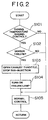
- step S101 the CPU determines whether a temperature raising control is being executed during an engine operation state in which it is highly necessary to lessen unburned fuel components in exhaust gas, for example, during a warm-up operation state, a low-speed and low-load operation state, or the like, that is, whether the engine A is in a state in which an exhaust temperature raising control is being executed based on execution of the sub-injection and operation of the exhaust throttle valve 15 in addition to the combustion attributed to main injection in an excess-air condition.
- step S101 determines whether there is a failure in the sensor 16 or 17. More specifically, for example, if there is a broken wire between the sensor and the ECU 4, the electrical connection between the sensor and the ECU 4 is cut off at the time of the break, so that it is determined that the sensor has a failure.
- step S102 functions as monitor means abnormality determination means for determining whether there is a sensor abnormality.
- Step S102 is included in the procedure of the program stored in the ROM of the ECU 4, and the attributes of step S102 exist in the ECU 4. Therefore, the ECU 4 can be said to be means for determining whether abnormality is present in sensors and the like.
- step S102 determines whether the determination in step S102 is affirmative. If the determination in step S102 is affirmative, the CPU proceeds to step S103. If the determination is negative, the CPU proceeds to step S105. In step S103, the CPU opens the exhaust throttle valve 15, which has been closed due to execution of exhaust throttling during the execution of the temperature raising control, and stops the sub-injection of the injectors 12.
- step S103 of opening the exhaust throttle valve 15 and stopping the sub-injection by the injectors 12 functions as an exhaust gas temperature increase stop means for stopping the operation of the exhaust gas temperature increase means when it is determined in step S102 that there is a sensor abnormality.
- the attributes of step S103 exist in the ECU 4 as in the case of step S102. Therefore, the ECU 4 can be said to be exhaust gas temperature increase stop means.
- step S104 the CPU informs a driving person or a passenger that there is a sensor failure, by a failure indicator lamp (not shown) provided in a passenger compartment, or a warning sound or the like.
- step S105 the CPU proceeds to an exhaust gas temperature control (hereinafter, referred to as "normal control") executed before the start of the exhaust temperature raising control. After that, the CPU returns to step S101 to repeat the routine in accordance with needs.
- normal control an exhaust gas temperature control
- the ECU 4 as monitor means abnormality determination means, determines that due to a failure of the exhaust air temperature sensor 16 or the like, which is an exhaust gas temperature increase monitor means, the expected function of the control cannot be carried out, that is, determines that there is a sensor failure, the ECU 4 performs the function of the exhaust gas temperature increase stop means to close the exhaust throttle valve 15, which has been open for an exhaust gas temperature increase, and to stop the execution of sub-injection of the injectors 12.
- the second embodiment differs from the first embodiment as follows.
- the operation of the exhaust gas temperature increase means is stopped when a failure occurs in a sensor that is an exhaust gas temperature increase monitor means.
- a value provided by an exhaust air temperature sensor or a back pressure sensor that indicates a temperature of exhaust gas is different from a predetermined value, it is simply determined that the exhaust temperature raising apparatus has an abnormality, aside from the determination as to which part of the exhaust temperature raising apparatus has an abnormality, and the operation of the exhaust gas temperature increase means is stopped.
- FIGURE 3 shows a flowchart (described below) regarding the aforementioned program.
- FIGURE 4 is a diagram for determining that a failure has occurred somewhere in the exhaust temperature raising apparatus if the back pressure or the exhaust gas temperature does not reach its target level (target range), that is, a predetermined temperature value, during a predetermined length of time during which the exhaust temperature raising control is being executed.
- target range target range
- the predetermined length of time during which the exhaust temperature raising control is being executed is suitably set as a determination time that is needed to determine whether there is a failure. Therefore, FIGURE 4 indicates whether the cylinder block 1 is in a failed state immediately after the determination time.
- the horizontal axis indicates time
- the vertical axes indicate, from above, whether the exhaust temperature raising control of the engine A is being executed, the value of back pressure, the value of exhaust gas temperature, and whether a failure is detected within the determination time.
- exhaust temperature raising control graph As for the levels indicated in the graph regarding the exhaust temperature raising control (hereinafter, referred to as "exhaust temperature raising control graph"), a graph line segement at level 1 indicates that the exhaust temperature raising control is being executed, and a graph line segment at level 0 indicates that the exhaust temperature raising control is not being executed.
- a predetermined time slot in the graph is set as a determination time. It is determined whether a failure is present based on the back pressure or the exhaust gas temperature occurring during the determination time.
- back pressure graph The graph regarding back pressure (hereinafter, referred to as “back pressure graph”) will next be described.
- a target level (target range) indicated in the back pressure graph indicates that if the back pressure is at the target level, the exhaust gas temperature is likely to reach the target exhaust gas temperature during the execution of the exhaust temperature raising control.
- the back pressure has a great effect on the exhaust gas temperature. If a certain exhaust gas temperature is secured through adjustment of the back pressure, it becomes easier to bring the exhaust gas temperature to the target exhaust gas temperature.
- the target level of the back pressure is not limited to a specified value, but may have a certain width, that is, may be set so as to mean values of back pressure belonging to a predetermined range.
- exhaust gas temperature graph indicates that there is no abnormality in the back pressure since the back pressure reaches the state of the target level within the determination time.
- Shown in the exhaust gas temperature graph are a thin graph line indicating a state of normal increase of the exhaust gas temperature to a target exhaust gas temperature and a thick line indicating a state in which the exhaust gas temperature is not normal.
- the graph is provided with a gradation region G which is a region indicating a target exhaust gas temperature.
- the thin graph line indicates that the exhaust gas temperature is at the target exhaust gas temperature during a portion of the determination time and a subsequent time period.
- the thick graph line indicates that the exhaust gas temperature does not reach the target exhaust gas temperature during or after the determination time.
- the exhaust gas temperature not reaching the target exhaust gas temperature indicates, for example, that the exhaust throttle valve 15, the injectors 12, that is, the fuel injection valves, the ECU 4, or the like is in an abnormal state due to any cause.
- a graph regarding failure determination indicates whether a failure is present after the elapse of the determination time. Since it takes a certain time to make a determination regarding failure, that is, since instant determination is impossible, a certain time allowance is provided to secure reliability in the failure determination.
- a failure level and a no-problem (normal) level are indicated.
- the failure level is a level corresponding to a situation where the exhaust gas temperature is not at the target exhaust gas temperature.
- the no-problem level is a level corresponding to a situation where the exhaust gas temperature is at the target exhaust gas temperature.
- the failure level and the no-problem level correspond to the thick graph line and the thin graph line in the exhaust gas temperature graph, respectively.
- the back pressure is normal during the determination time. Therefore, if the exhaust gas temperature graph line is at a target exhaust gas temperature level at the end of the determination time, it is determined that there is no abnormality in the exhaust throttle valve 15, the injectors 12, that is, the fuel injection valves, the ECU 4, or the like. Conversely, if the exhaust gas temperature graph line is not at the target exhaust gas temperature level at the end of the determination time, it is determined that there is an abnormality in the exhaust throttle valve 15, the injectors 12, that is, the fuel injection valves, the ECU 4, or the like.
- step S201 it is determined whether a temperature raising control is being executed during an engine operation state in which it is highly necessary to lessen unburned fuel components in exhaust gas, for example, during a warm-up operation state, a low-speed and low-load operation state, or the like, that is, whether the engine A is in a state in which an exhaust temperature raising control is being executed based on execution of the sub-injection and operation of the exhaust throttle valve 15 in addition to the combustion attributed to main injection in an excess-air condition.
- step S201 the CPU makes an affirmative determination (determination that the exhaust gas temperature graph line is at level 1), the CPU proceeds to step S202. If a negative determination (determination that the exhaust gas temperature graph line is at level 0) is made, the CPU proceeds to step S204.
- step S202 the CPU determines whether the detection value detected by the back pressure sensor 17 disposed in the exhaust passage, that is, the back pressure, equals the target level, that is, a predetermined value. If the determination in step S202 is affirmative, it is considered that the back pressure is at the target level, i.e., that there is no abnormality regarding the state of exhaust gas temperature increase, and the process proceeds to step S203. If the determination in step S202 is negative, it is considered that the back pressure is not at the target level, and the process proceeds to step S204. As mentioned above, the back pressure has a great effect on the exhaust gas temperature, that is, the exhaust gas temperature depends on the magnitude of the back pressure. Therefore, step S202 of determining whether the back pressure is at the target level is regarded as exhaust gas temperature increase abnormality determination means (ECU) for determining whether there is an abnormality regarding the state of exhaust gas temperature increase.
- ECU exhaust gas temperature increase abnormality determination means
- step S203 the CPU determines whether the exhaust gas temperature is at the aforementioned target exhaust gas temperature, that is, the target level (see the exhaust gas temperature graph). If in step S203, the CPU makes an affirmative determination (determination that the exhaust gas temperature is within the gradation region G), that is, if the CPU determines that there is no abnormality regarding exhaust gas temperature increase, the CPU repeats this routine if necessary. If in step S203, the CPU makes a negative determination (determination that the exhaust gas temperature is not within the gradation region G), the CPU proceeds to step S204.
- step S203 of determining whether the exhaust gas temperature is at the target exhaust gas temperature can be said to be an exhaust gas temperature increase abnormality determination means for determining whether there is an abnormality regarding exhaust gas temperature increase. If the determination in step S203 is affirmative, that is, if the exhaust gas temperature is within the gradation region G, it is determined that there is no failure (see the no-problem level in the failure determination graph). If the exhaust gas temperature is not within the gradation region G, it is determined that there is an abnormality (see the failure level in the failure determination graph).
- step S203 and S202 are included in the procedure of the program stored in the ROM of the ECU 4, and the attributes of step S203 and S202 exist in the ECU 4. Therefore, the ECU 4 can be said to be an exhaust gas temperature increase abnormality determination means.
- step S204 the CPU opens the exhaust throttle valve 15 and stops the sub-injection.
- step S204 functions as an exhaust gas temperature increase stop means for stopping the operation of the exhaust gas temperature increase means when it is determined in step S202 or S203 that at least one of the back pressure and the exhaust gas temperature is not at the target level.
- the attributes of step S204 exist in the ECU 4 as in the case of steps S202 and S203. Therefore, the ECU 4 can be said to be an exhaust gas temperature increase stop means.
- step S205 the CPU informs a driving person or a passenger that there is a failure in the exhaust throttle valve 15, the injectors 12, the ECU 4, or the like, by a failure indicator lamp (not shown) provided in a passenger compartment, or a warning sound or the like.
- step S206 the CPU discontinues the exhaust temperature raising control, and executes a control (hereinafter, referred to as "normal control") executed before the exhaust temperature raising control.
- the program illustrated in FIGURE 3 and the diagram shown in FIGURE 4 are stored in the ROM, and are called by the CPU when necessary.
- the detection value provided by the exhaust air temperature sensor 16 or the detection value provided by the back pressure sensor 17 does not reach the target level, that is, if the ECU 4, as an exhaust gas temperature increase abnormality determination means, determines that there is an abnormality regarding the state exhaust gas temperature increase, it is considered that there is an abnormality in the exhaust gas temperature increase means, and the ECU 4, as an exhaust gas temperature increase stop means, stops the exhaust gas temperature increase means.
- an injector 12 that is, a component element of the exhaust gas temperature increase means, has a failure and is unable to supply fuel properly and, therefore, the combustion level is insufficient, and that the pressure in the exhaust passage 3 is insufficient due to a malfunction of the exhaust throttle valve 15, or the like, and that the exhaust air temperature sensor 16 has an abnormality and cannot provide an accurate detection value, and so on.
- the operation of the exhaust temperature raising apparatus is continued by closing the exhaust throttle valve 15 and executing the sub-injection in addition to the main injection in an excess-air state, undesired excessive combustion may be caused, so that the amount of unburned HCs may further increase or the catalyst temperature may increase more than necessary. Therefore, if an abnormality is detected as described above, the ECU 4, as an exhaust gas temperature increase stop means, stops the operation of the exhaust gas temperature increase means, in order to prevent an unexpected increase in the amount of HCs and an abnormal rise in the temperature of the catalyst.
- An exhaust temperature raising apparatus has an exhaust throttle valve (15) that adjusts the engine exhaust amount based on the amount of throttling, and an injector (12) that performs main injection and a sub-injection directly into a cylinder, a combination of an ECU (4), the injector (12), and the exhaust throttle valve (15) as exhaust gas temperature increase means for, during an engine warm-up, performing and controlling the exhaust throttling by the exhaust throttle valve and performing and controlling an exhaust gas temperature increase through combustion attributed to the main injection performed in an excess-air condition and combustion attributed to the sub-injection, an exhaust gas temperature sensor (16) that monitors a state of temperature increase of the exhaust gas caused by performance of the exhaust gas temperature increase means, and the ECU (4) as monitor means abnormality determination means for determining whether the exhaust gas temperature sensor (16) has an abnormality, and the ECU (4) as exhaust gas temperature increase stop means for stopping the operation of the exhaust gas temperature increase means when the ECU (4) determines that the exhaust gas temperature sensor (16) has an abnormality.
Landscapes
- Engineering & Computer Science (AREA)
- Chemical & Material Sciences (AREA)
- Combustion & Propulsion (AREA)
- Mechanical Engineering (AREA)
- General Engineering & Computer Science (AREA)
- Control Of Throttle Valves Provided In The Intake System Or In The Exhaust System (AREA)
- Electrical Control Of Air Or Fuel Supplied To Internal-Combustion Engine (AREA)
- Combined Controls Of Internal Combustion Engines (AREA)
- Exhaust Gas After Treatment (AREA)
Applications Claiming Priority (2)
| Application Number | Priority Date | Filing Date | Title |
|---|---|---|---|
| JP30438899 | 1999-10-26 | ||
| JP30438899A JP3633401B2 (ja) | 1999-10-26 | 1999-10-26 | 内燃機関の排気昇温装置 |
Publications (3)
| Publication Number | Publication Date |
|---|---|
| EP1096126A2 true EP1096126A2 (de) | 2001-05-02 |
| EP1096126A3 EP1096126A3 (de) | 2002-09-25 |
| EP1096126B1 EP1096126B1 (de) | 2005-12-14 |
Family
ID=17932429
Family Applications (1)
| Application Number | Title | Priority Date | Filing Date |
|---|---|---|---|
| EP00123124A Expired - Lifetime EP1096126B1 (de) | 1999-10-26 | 2000-10-25 | Vorrichtung und Verfahern zur Erhöhung der Abgastemperatur bei einer Brennkraftmaschine |
Country Status (4)
| Country | Link |
|---|---|
| US (1) | US6381952B1 (de) |
| EP (1) | EP1096126B1 (de) |
| JP (1) | JP3633401B2 (de) |
| DE (1) | DE60024756T2 (de) |
Cited By (12)
| Publication number | Priority date | Publication date | Assignee | Title |
|---|---|---|---|---|
| US6536209B2 (en) | 2001-06-26 | 2003-03-25 | Caterpillar Inc | Post injections during cold operation |
| EP1099843A3 (de) * | 1999-11-09 | 2003-07-09 | Honda Giken Kogyo Kabushiki Kaisha | Steuerungssystem für eine Brennkraftmaschine |
| US6688101B2 (en) | 1999-09-11 | 2004-02-10 | Honda Giken Kogyo Kabushiki Kaisha | Control system for internal combustion engine |
| EP1365137A4 (de) * | 2001-02-26 | 2004-04-07 | Mitsubishi Motors Corp | Abgasreiniger für brennkraftmaschinen |
| ES2263340A1 (es) * | 2003-08-06 | 2006-12-01 | Honda Motor Co., Ltd | Dispositivo de control de potencia de motor. |
| EP1942262A2 (de) | 2006-12-26 | 2008-07-09 | Toyota Jidosha Kabushiki Kaisha | Abgasreinigungsvorrichtung und Verfahren für Verbrennungsmotoren |
| EP1900928A4 (de) * | 2005-07-06 | 2009-04-29 | Toyota Motor Co Ltd | Abgasreinigungssystem für einen verbrennungsmotor |
| WO2010003780A1 (de) * | 2008-07-11 | 2010-01-14 | Continental Automotive Gmbh | Verfahren und diagnosegerät zum erkennen einer fehlfunktion an einer einspritzanlage |
| JP2012117512A (ja) * | 2010-11-30 | 2012-06-21 | Hyundai Motor Co Ltd | 排気ガス後処理方法 |
| EP1662123A3 (de) * | 2004-11-26 | 2013-04-17 | Toyota Jidosha Kabushiki Kaisha | Vorrichtung zur Erhöhung der Temperatur eines Katalysators für Brennkraftmaschine |
| US9212587B2 (en) | 2014-02-25 | 2015-12-15 | Cummins Inc. | Exhaust throttle control for aftertreatment system thermal management |
| CN109667680A (zh) * | 2018-12-28 | 2019-04-23 | 潍柴动力股份有限公司 | 一种排温热管理方法及装置、系统 |
Families Citing this family (29)
| Publication number | Priority date | Publication date | Assignee | Title |
|---|---|---|---|---|
| JP4061467B2 (ja) * | 2002-03-15 | 2008-03-19 | 三菱自動車工業株式会社 | 内燃機関の排気浄化装置 |
| JP3858749B2 (ja) * | 2002-04-23 | 2006-12-20 | トヨタ自動車株式会社 | 内燃機関の排気浄化装置 |
| JP4333289B2 (ja) * | 2003-09-03 | 2009-09-16 | いすゞ自動車株式会社 | 排気ガス浄化システム |
| JP4321332B2 (ja) * | 2004-04-01 | 2009-08-26 | トヨタ自動車株式会社 | 内燃機関の排気浄化装置 |
| JP3992016B2 (ja) * | 2004-05-17 | 2007-10-17 | トヨタ自動車株式会社 | 予混合圧縮自着火式内燃機関の制御装置 |
| US7263824B2 (en) * | 2004-12-03 | 2007-09-04 | Cummins, Inc. | Exhaust gas aftertreatment device for an internal combustion engine |
| JP4606939B2 (ja) | 2005-05-18 | 2011-01-05 | 本田技研工業株式会社 | 内燃機関の排気浄化装置 |
| JP2007162611A (ja) * | 2005-12-15 | 2007-06-28 | Toyota Industries Corp | インジェクタ作動不良検出装置およびそれを備えたインジェクタ作動不良除去装置 |
| JP2007297918A (ja) * | 2006-04-27 | 2007-11-15 | Toyota Motor Corp | 内燃機関の排気浄化装置 |
| JP4304527B2 (ja) * | 2006-07-03 | 2009-07-29 | トヨタ自動車株式会社 | 内燃機関の排気浄化装置 |
| WO2008036010A1 (en) * | 2006-09-19 | 2008-03-27 | Industriell Plåtproduktion Ab | Exhaust gas system |
| US20080155962A1 (en) * | 2006-12-06 | 2008-07-03 | Siemens Vdo Automotive Canada Inc. | Pressure or temperature sensor control of a variable position exhaust throttle valve |
| JP4845762B2 (ja) * | 2007-02-13 | 2011-12-28 | 本田技研工業株式会社 | 内燃機関の排ガス浄化装置 |
| JP4788631B2 (ja) * | 2007-03-02 | 2011-10-05 | いすゞ自動車株式会社 | エキゾーストスロットルバルブ診断装置および方法 |
| JP4325704B2 (ja) * | 2007-06-06 | 2009-09-02 | トヨタ自動車株式会社 | 内燃機関の排気浄化システム |
| US7523653B2 (en) * | 2007-06-14 | 2009-04-28 | Ford Gobal Technologies, Llc | Exhaust temperature sensor monitoring |
| WO2009023793A1 (en) * | 2007-08-14 | 2009-02-19 | Plasmadrive, Inc. | Barometric pressure regulator circuit |
| WO2009081231A1 (en) * | 2007-12-21 | 2009-07-02 | Renault Trucks | Thermal energy containing arrangement for an exhaust gas purification device |
| US8079351B2 (en) * | 2008-01-10 | 2011-12-20 | Ford Global Technologies, Llc | Temperature sensor diagnostics |
| JP5500867B2 (ja) * | 2009-04-30 | 2014-05-21 | 日野自動車株式会社 | 排気浄化装置 |
| JP5656280B2 (ja) * | 2009-12-11 | 2015-01-21 | ボルボ パワートレイン アーベーVolvo Powertrain Ab | 後処理用燃料添加装置 |
| EP2513455B1 (de) * | 2009-12-18 | 2017-01-11 | Conti Temic microelectronic GmbH | Überwachungskonzept in einem steuergerät |
| JP5880187B2 (ja) * | 2012-03-21 | 2016-03-08 | 株式会社デンソー | 燃料噴射弁検査装置 |
| US8997457B2 (en) * | 2012-09-10 | 2015-04-07 | Ford Global Technologies, Llc | Catalyst heating with exhaust back-pressure |
| US9239016B2 (en) * | 2012-09-10 | 2016-01-19 | Ford Global Technologies, Llc | Catalyst heating with exhaust back-pressure |
| CN106285869B (zh) * | 2016-08-30 | 2019-01-15 | 潍柴动力股份有限公司 | 排气后处理方法 |
| JP7045160B2 (ja) * | 2016-12-08 | 2022-03-31 | 三菱重工業株式会社 | 非常用発電用エンジンの制御装置、非常用発電用エンジン、及び非常用発電用エンジンの保守運転方法 |
| DE102017219172A1 (de) * | 2017-10-25 | 2019-04-25 | Bayerische Motoren Werke Aktiengesellschaft | Steuereinrichtung zum Ansteuern eines Verbrennungsmotors und Verfahren zum Erwärmen einer Abgasreinigungseinrichtung |
| US11002166B2 (en) * | 2019-05-17 | 2021-05-11 | Ford Global Technologies, Llc | Methods and systems for an active exhaust valve |
Citations (1)
| Publication number | Priority date | Publication date | Assignee | Title |
|---|---|---|---|---|
| JPS4980414A (de) | 1972-12-08 | 1974-08-02 |
Family Cites Families (18)
| Publication number | Priority date | Publication date | Assignee | Title |
|---|---|---|---|---|
| JPH04111540A (ja) | 1990-08-30 | 1992-04-13 | Matsushita Electric Ind Co Ltd | ダブルスーパチューナ |
| JP2913868B2 (ja) * | 1991-03-08 | 1999-06-28 | トヨタ自動車株式会社 | 内燃機関の排ガス浄化装置 |
| JP3553146B2 (ja) * | 1994-08-22 | 2004-08-11 | 本田技研工業株式会社 | 電気加熱式触媒制御装置 |
| JPH08100638A (ja) | 1994-09-29 | 1996-04-16 | Fuji Heavy Ind Ltd | 筒内噴射エンジンの触媒活性化制御装置 |
| JP3052777B2 (ja) | 1995-04-27 | 2000-06-19 | 三菱自動車工業株式会社 | 筒内噴射型内燃機関 |
| JP3671455B2 (ja) * | 1995-04-28 | 2005-07-13 | 株式会社デンソー | 内燃機関の排気浄化装置 |
| JPH0949422A (ja) * | 1995-08-09 | 1997-02-18 | Denso Corp | 内燃機関の排出ガス浄化装置 |
| CN1077212C (zh) * | 1996-07-02 | 2002-01-02 | 三菱自动车工业株式会社 | 缸内喷射内燃机用废气加热系统 |
| US5839275A (en) * | 1996-08-20 | 1998-11-24 | Toyota Jidosha Kabushiki Kaisha | Fuel injection control device for a direct injection type engine |
| JPH10131792A (ja) | 1996-10-31 | 1998-05-19 | Yamaha Motor Co Ltd | 内燃エンジンの希薄燃焼制御方法 |
| JP3257430B2 (ja) * | 1997-01-29 | 2002-02-18 | 三菱自動車工業株式会社 | 排気昇温装置 |
| JP3656354B2 (ja) | 1997-02-26 | 2005-06-08 | トヨタ自動車株式会社 | 内燃機関の排気浄化装置 |
| DE19715921A1 (de) * | 1997-04-16 | 1998-10-22 | Schatz Thermo Gastech Gmbh | Verfahren und Vorrichtung zur Schadstoffminderung |
| US5983630A (en) * | 1997-07-01 | 1999-11-16 | Toyota Jidosha Kabushiki Kaisha | Fuel injecting device for an engine |
| JP3799758B2 (ja) * | 1997-08-05 | 2006-07-19 | トヨタ自動車株式会社 | 内燃機関の触媒再生装置 |
| JP3564966B2 (ja) * | 1997-09-19 | 2004-09-15 | トヨタ自動車株式会社 | 排気浄化装置の故障診断装置 |
| JP3277881B2 (ja) * | 1998-04-06 | 2002-04-22 | トヨタ自動車株式会社 | 内燃機関の排気浄化装置 |
| US6164065A (en) * | 1999-11-12 | 2000-12-26 | Ford Global Technologies, Inc. | After treatment system for a variable displacement engine |
-
1999
- 1999-10-26 JP JP30438899A patent/JP3633401B2/ja not_active Expired - Fee Related
-
2000
- 2000-10-25 EP EP00123124A patent/EP1096126B1/de not_active Expired - Lifetime
- 2000-10-25 DE DE60024756T patent/DE60024756T2/de not_active Expired - Lifetime
- 2000-10-26 US US09/696,024 patent/US6381952B1/en not_active Expired - Fee Related
Patent Citations (1)
| Publication number | Priority date | Publication date | Assignee | Title |
|---|---|---|---|---|
| JPS4980414A (de) | 1972-12-08 | 1974-08-02 |
Cited By (17)
| Publication number | Priority date | Publication date | Assignee | Title |
|---|---|---|---|---|
| US6688101B2 (en) | 1999-09-11 | 2004-02-10 | Honda Giken Kogyo Kabushiki Kaisha | Control system for internal combustion engine |
| EP1099843A3 (de) * | 1999-11-09 | 2003-07-09 | Honda Giken Kogyo Kabushiki Kaisha | Steuerungssystem für eine Brennkraftmaschine |
| EP1365137A4 (de) * | 2001-02-26 | 2004-04-07 | Mitsubishi Motors Corp | Abgasreiniger für brennkraftmaschinen |
| GB2382622A (en) * | 2001-06-26 | 2003-06-04 | Caterpillar Inc | Post-injection during cold operation to heat i.c. engine exhaust system |
| GB2382622B (en) * | 2001-06-26 | 2005-05-25 | Caterpillar Inc | Post injections during cold operation |
| US6536209B2 (en) | 2001-06-26 | 2003-03-25 | Caterpillar Inc | Post injections during cold operation |
| ES2263340A1 (es) * | 2003-08-06 | 2006-12-01 | Honda Motor Co., Ltd | Dispositivo de control de potencia de motor. |
| ES2263340B1 (es) * | 2003-08-06 | 2007-08-16 | Honda Motor Co., Ltd | Dispositivo de control de potencia de motor. |
| EP1662123A3 (de) * | 2004-11-26 | 2013-04-17 | Toyota Jidosha Kabushiki Kaisha | Vorrichtung zur Erhöhung der Temperatur eines Katalysators für Brennkraftmaschine |
| EP1900928A4 (de) * | 2005-07-06 | 2009-04-29 | Toyota Motor Co Ltd | Abgasreinigungssystem für einen verbrennungsmotor |
| EP1942262A2 (de) | 2006-12-26 | 2008-07-09 | Toyota Jidosha Kabushiki Kaisha | Abgasreinigungsvorrichtung und Verfahren für Verbrennungsmotoren |
| US7918084B2 (en) | 2006-12-26 | 2011-04-05 | Toyota Jidosha Kabushiki Kaisha | Exhaust gas purification apparatus and method for internal combustion engines |
| EP1942262A3 (de) * | 2006-12-26 | 2009-07-29 | Toyota Jidosha Kabushiki Kaisha | Abgasreinigungsvorrichtung und Verfahren für Verbrennungsmotoren |
| WO2010003780A1 (de) * | 2008-07-11 | 2010-01-14 | Continental Automotive Gmbh | Verfahren und diagnosegerät zum erkennen einer fehlfunktion an einer einspritzanlage |
| JP2012117512A (ja) * | 2010-11-30 | 2012-06-21 | Hyundai Motor Co Ltd | 排気ガス後処理方法 |
| US9212587B2 (en) | 2014-02-25 | 2015-12-15 | Cummins Inc. | Exhaust throttle control for aftertreatment system thermal management |
| CN109667680A (zh) * | 2018-12-28 | 2019-04-23 | 潍柴动力股份有限公司 | 一种排温热管理方法及装置、系统 |
Also Published As
| Publication number | Publication date |
|---|---|
| DE60024756D1 (de) | 2006-01-19 |
| DE60024756T2 (de) | 2006-08-17 |
| EP1096126A3 (de) | 2002-09-25 |
| JP3633401B2 (ja) | 2005-03-30 |
| US6381952B1 (en) | 2002-05-07 |
| JP2001123870A (ja) | 2001-05-08 |
| EP1096126B1 (de) | 2005-12-14 |
Similar Documents
| Publication | Publication Date | Title |
|---|---|---|
| EP1096126B1 (de) | Vorrichtung und Verfahern zur Erhöhung der Abgastemperatur bei einer Brennkraftmaschine | |
| KR100627595B1 (ko) | 내연기관의 배기 정화 장치 | |
| US6732707B2 (en) | Control system and method for internal combustion engine | |
| JP3562382B2 (ja) | 内燃機関のサーモスタット故障診断装置 | |
| US6792346B2 (en) | Diagnostic apparatus for an engine | |
| US6918245B2 (en) | Secondary air feeding apparatus and method of detecting abnormality in the apparatus | |
| US20080202482A1 (en) | EGR system for internal combustion engine | |
| CN102192027A (zh) | 用于发动机的燃料供给控制设备及其燃料供给控制方法 | |
| US5542400A (en) | Apparatus and method for determining a failure of an EGR apparatus | |
| JP2001510261A (ja) | ターボチャージャーを制御するシステム及び方法 | |
| JP3616683B2 (ja) | 内燃エンジンのエアポンプの異常検出装置 | |
| JP3937926B2 (ja) | 排気再循環制御装置の異常判定方法 | |
| US20100018189A1 (en) | Control system of internal combustion engine | |
| JP3642169B2 (ja) | エンジンのegr診断装置 | |
| JP2002349357A (ja) | 排出ガス環流システムの異常診断装置 | |
| JP7186029B2 (ja) | 内燃機関の制御装置及び診断方法 | |
| JP3867189B2 (ja) | 吸気系の異常検出装置 | |
| JP3186339B2 (ja) | ホットワイヤ式エアフローメータの異常検出装置 | |
| JP3769820B2 (ja) | エンジンの失火診断装置 | |
| US7104046B2 (en) | Controller for an internal combustion engine | |
| EP2742217A1 (de) | Steuervorrichtung für einen verbrennungsmotor und steuerverfahren für einen verbrennungsmotor | |
| KR100219453B1 (ko) | Egr 모니터링 방법 | |
| JP3478027B2 (ja) | 内燃機関の吸気制御装置 | |
| JP2020045818A (ja) | 診断装置 | |
| JPH01200044A (ja) | 車両用内燃機関のフェールセーフ装置 |
Legal Events
| Date | Code | Title | Description |
|---|---|---|---|
| PUAI | Public reference made under article 153(3) epc to a published international application that has entered the european phase |
Free format text: ORIGINAL CODE: 0009012 |
|
| 17P | Request for examination filed |
Effective date: 20001025 |
|
| AK | Designated contracting states |
Kind code of ref document: A2 Designated state(s): AT BE CH CY DE DK ES FI FR GB GR IE IT LI LU MC NL PT SE |
|
| AX | Request for extension of the european patent |
Free format text: AL;LT;LV;MK;RO;SI |
|
| PUAL | Search report despatched |
Free format text: ORIGINAL CODE: 0009013 |
|
| AK | Designated contracting states |
Kind code of ref document: A3 Designated state(s): AT BE CH CY DE DK ES FI FR GB GR IE IT LI LU MC NL PT SE |
|
| AX | Request for extension of the european patent |
Free format text: AL;LT;LV;MK;RO;SI |
|
| AKX | Designation fees paid |
Designated state(s): DE FR GB |
|
| GRAP | Despatch of communication of intention to grant a patent |
Free format text: ORIGINAL CODE: EPIDOSNIGR1 |
|
| GRAS | Grant fee paid |
Free format text: ORIGINAL CODE: EPIDOSNIGR3 |
|
| GRAA | (expected) grant |
Free format text: ORIGINAL CODE: 0009210 |
|
| AK | Designated contracting states |
Kind code of ref document: B1 Designated state(s): DE FR GB |
|
| REG | Reference to a national code |
Ref country code: GB Ref legal event code: FG4D |
|
| REF | Corresponds to: |
Ref document number: 60024756 Country of ref document: DE Date of ref document: 20060119 Kind code of ref document: P |
|
| ET | Fr: translation filed | ||
| PLBE | No opposition filed within time limit |
Free format text: ORIGINAL CODE: 0009261 |
|
| STAA | Information on the status of an ep patent application or granted ep patent |
Free format text: STATUS: NO OPPOSITION FILED WITHIN TIME LIMIT |
|
| 26N | No opposition filed |
Effective date: 20060915 |
|
| PGFP | Annual fee paid to national office [announced via postgrant information from national office to epo] |
Ref country code: FR Payment date: 20081014 Year of fee payment: 9 |
|
| PGFP | Annual fee paid to national office [announced via postgrant information from national office to epo] |
Ref country code: GB Payment date: 20081022 Year of fee payment: 9 |
|
| REG | Reference to a national code |
Ref country code: GB Ref legal event code: 746 Effective date: 20090616 |
|
| REG | Reference to a national code |
Ref country code: FR Ref legal event code: ST Effective date: 20100630 |
|
| PG25 | Lapsed in a contracting state [announced via postgrant information from national office to epo] |
Ref country code: FR Free format text: LAPSE BECAUSE OF NON-PAYMENT OF DUE FEES Effective date: 20091102 |
|
| PG25 | Lapsed in a contracting state [announced via postgrant information from national office to epo] |
Ref country code: GB Free format text: LAPSE BECAUSE OF NON-PAYMENT OF DUE FEES Effective date: 20091025 |
|
| PGFP | Annual fee paid to national office [announced via postgrant information from national office to epo] |
Ref country code: DE Payment date: 20101020 Year of fee payment: 11 |
|
| PG25 | Lapsed in a contracting state [announced via postgrant information from national office to epo] |
Ref country code: DE Free format text: LAPSE BECAUSE OF NON-PAYMENT OF DUE FEES Effective date: 20130501 |
|
| REG | Reference to a national code |
Ref country code: DE Ref legal event code: R119 Ref document number: 60024756 Country of ref document: DE Effective date: 20130501 |