EP1096242A2 - Drucksensor - Google Patents
Drucksensor Download PDFInfo
- Publication number
- EP1096242A2 EP1096242A2 EP00122340A EP00122340A EP1096242A2 EP 1096242 A2 EP1096242 A2 EP 1096242A2 EP 00122340 A EP00122340 A EP 00122340A EP 00122340 A EP00122340 A EP 00122340A EP 1096242 A2 EP1096242 A2 EP 1096242A2
- Authority
- EP
- European Patent Office
- Prior art keywords
- pressure
- sensor membrane
- pressure sensor
- membrane
- sensor according
- Prior art date
- Legal status (The legal status is an assumption and is not a legal conclusion. Google has not performed a legal analysis and makes no representation as to the accuracy of the status listed.)
- Granted
Links
Images


Classifications
-
- G—PHYSICS
- G01—MEASURING; TESTING
- G01L—MEASURING FORCE, STRESS, TORQUE, WORK, MECHANICAL POWER, MECHANICAL EFFICIENCY, OR FLUID PRESSURE
- G01L9/00—Measuring steady of quasi-steady pressure of fluid or fluent solid material by electric or magnetic pressure-sensitive elements; Transmitting or indicating the displacement of mechanical pressure-sensitive elements, used to measure the steady or quasi-steady pressure of a fluid or fluent solid material, by electric or magnetic means
- G01L9/02—Measuring steady of quasi-steady pressure of fluid or fluent solid material by electric or magnetic pressure-sensitive elements; Transmitting or indicating the displacement of mechanical pressure-sensitive elements, used to measure the steady or quasi-steady pressure of a fluid or fluent solid material, by electric or magnetic means by making use of variations in ohmic resistance, e.g. of potentiometers, electric circuits therefor, e.g. bridges, amplifiers or signal conditioning
-
- G—PHYSICS
- G01—MEASURING; TESTING
- G01L—MEASURING FORCE, STRESS, TORQUE, WORK, MECHANICAL POWER, MECHANICAL EFFICIENCY, OR FLUID PRESSURE
- G01L9/00—Measuring steady of quasi-steady pressure of fluid or fluent solid material by electric or magnetic pressure-sensitive elements; Transmitting or indicating the displacement of mechanical pressure-sensitive elements, used to measure the steady or quasi-steady pressure of a fluid or fluent solid material, by electric or magnetic means
- G01L9/0041—Transmitting or indicating the displacement of flexible diaphragms
- G01L9/0051—Transmitting or indicating the displacement of flexible diaphragms using variations in ohmic resistance
-
- G—PHYSICS
- G01—MEASURING; TESTING
- G01L—MEASURING FORCE, STRESS, TORQUE, WORK, MECHANICAL POWER, MECHANICAL EFFICIENCY, OR FLUID PRESSURE
- G01L9/00—Measuring steady of quasi-steady pressure of fluid or fluent solid material by electric or magnetic pressure-sensitive elements; Transmitting or indicating the displacement of mechanical pressure-sensitive elements, used to measure the steady or quasi-steady pressure of a fluid or fluent solid material, by electric or magnetic means
- G01L9/0041—Transmitting or indicating the displacement of flexible diaphragms
- G01L9/0042—Constructional details associated with semiconductive diaphragm sensors, e.g. etching, or constructional details of non-semiconductive diaphragms
- G01L9/0048—Details about the mounting of the diaphragm to its support or about the diaphragm edges, e.g. notches, round shapes for stress relief
Definitions
- the invention relates to a pressure sensor with a sensor membrane, that on one of their surfaces by the media pressure to be determined is acted upon.
- Pressure sensors are used in different depending on their area of application Designs executed. Only come for use in motor vehicles Robust designs are considered that operate in a wide temperature range work reliably for many years, during the absolute Measurement accuracy is less important. Most pressure sensors work with a pressure-dependent stroke, the size of which is a measure of the measured pressure. An elastic sensor membrane based on one of their Surfaces with a constant reference pressure and on their opposite surface by the media pressure to be determined is subjected to a deflection due to the differential pressure, their size e.g. via a coupled potentiometer electrical measurement signal can be implemented. For triggering pressure-dependent switching processes are caused by the stroke of the sensor membrane Limit switch operated directly or indirectly. In all cases moving parts are required, which over long periods of time shocks, Wear and strong temperature influences are exposed. Also is the media separation between the two sides of a sensor membrane problematic in these circumstances.
- a pressure sensor is created by the invention its robustness, its simple design and small size make it special is suitable for use in motor vehicles and for both Generation of a pressure-proportional measured variable as well as for triggering of pressure-dependent switching operations is suitable.
- the sensor membrane is on its opposite Rigidly supported surface.
- the sensor membrane consists of a Elastomer material, in its electrically non-conductive mass fine Particles of electrically conductive material distributed homogeneously in such density are embedded.
- One caused by media printing Compression of the membrane leads to a measurable change in the Surface resistance of the sensor membrane because the particles are made of electrical conductive material are moved closer together and consequently the The probability of touching an adjacent particle increases.
- the pressure sensor according to the invention does not require any movable Parts, so that the problems associated with moving parts such as Susceptibility to failure, large installation space, wear, high manufacturing costs and there are no leaks.
- the electrical sheet resistance of the Sensor membrane can be made by contacting at two spaced measuring points can be determined by means of known measuring circuits.
- a pressure-proportional measurement signal is advantageously a bridge circuit used.
- simple differential amplifier circuits are suitable for pressure-dependent triggering of switching processes.
- the sensor membrane on its rigidly supported side by two measuring contacts contacted.
- the sensor membrane as such ensures one perfect media separation.
- the structure of the pressure sensor is preferably based on the simple Principle of bracing the sensor membrane with a support block between ring-shaped components with the interposition of sealing rings.
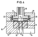
- the pressure sensor has essentials Functional element on a sensor membrane 12, which consists of a electrically insulating elastomer material with in its mass embedded particles of an electrically conductive material consists.
- the electrically conductive particles are of such density provided that the sensor membrane has a measurable volume resistance and thus also give surface resistance.
- the electrical volume or Surface resistance increases measurably when the membrane mass is compressed by bringing the conductive particles closer together and the The probability of touching neighboring particles increases.
- suitable elastomer material is silicone rubber, in which electrical conductive particles are embedded in a homogeneous distribution. The concentration of the conductive particles can be determined empirically. Examples for suitable particles are: nickel, silver, copper, silver-plated copper or Glass particles.
- the sensor membrane 12 is a flat, circular disc that is on one of its two faces on an end face of a cylindrical Support block 14 rests and is rigidly supported on this.
- In the out existing electrically insulating material support block 14 are two Contact pins 16 let in, on their facing the sensor membrane Ends are widened and to form measuring contacts of the sensor membrane 12.
- the opposite ends of the Contact pins 16 protrude from the support block and form connecting pins for a connector.
- the support body 14 is suitable and flush in a cylindrical depression of an annular base body 18 added.
- a pressure ring 20 is on its two ring surfaces with three concentric grooves for receiving O-rings and lies on the surface of the sensor membrane 12 facing away from the support block 14 on. With its opposite ring surface, the pressure ring is 20th by screws 22 against an annular flange 24 at one end of a Connection piece 26 clamped. The by the pressure ring 20 and Ring flange 24 with connecting piece 26 is formed by overlap a clamping ring 28, which by means of clamping screws 30 against the Base body 18 is clamped, causing the pressure ring against the surface the sensor membrane 12 is pressed. The contact pressure can be between Clamping ring 28 and base body 18 inserted spacers defined become.
- the annular base body 18 forms one in the middle Plug shaft 32 into which the contact pins 16 protrude. To the Plug shaft 32 is followed by a radial cable routing channel 34.
- a precise alignment of the assembled components of the Pressure sensor is achieved by dowel pins 36, which in corresponding, aligned bores of the clamping ring 28 and the base body 18 are used.
- the relative rotational positions are also due to the dowel pins the components of the pressure sensor precisely defined.
- the connecting piece 26 surrounds a media channel in the central opening of the pressure ring 20, which opens the exposed part surrounding the sensor membrane surface. This sensor membrane surface is over the Connection piece 26 is subjected to the media pressure to be determined. The media is separated by the sensor membrane itself, in Connection with the O-rings inserted in the grooves of the pressure ring 20.
- the contact pins are via a connector (not shown) connected to an electronic circuit which, depending on Application of the pressure sensor e.g. as a measuring bridge to generate a pressure-proportional measurement signal or as a differential amplifier for pressure-dependent triggering of switching operations can be formed.
- the pressure sensor e.g. as a measuring bridge to generate a pressure-proportional measurement signal or as a differential amplifier for pressure-dependent triggering of switching operations can be formed.
- the media pressure introduced via the connecting piece 26 Mass of the sensor membrane 12 is compressed, making its electrical Volume resistance and thus also via the contact pins 16 decreased sheet resistance is reduced.
- To maximize the Measurement signal are the ends of the contact pins 16 in the area of clamped circumferential edge of the sensor membrane 12 arranged.
- the sensor membrane 12 is one round, flat material disc. But it can also be used as a special Applications of adapted three-dimensional shaped bodies.
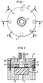
- FIGS. 1 to 5 The embodiment shown in FIGS. 1 to 5 is suitable especially for testing purposes because of the use of clamping screws 30 a detachable assembly is made possible.
- connection piece 26 which is provided with an external thread 26a, in one piece with a Housing body 40 is formed, in which the support block 14 is inserted.
- the Support block 14 With a flanged edge 42 of the housing body 40 is the Support block 14 with the sensor membrane 12 resting thereon clamped.
- the sensor membrane 12 has one on its outer circumference integrally formed ring bead 12a against an opposite Annular surface 40a is pressed inside the housing body 40 and the Construction seals.
- the contact pins 16 protrude into the support block 14 attached electronics module 44, led out of the pins 46 are.
- the electronics module 44 contains at least the high-resistance ones Components of the measuring circuit by the changes in resistance of the Sensor membrane 12 are converted into an electrical signal.
- One of the contact pins 16 can be omitted if the sensor membrane 12, in particular on its outer circumference, rests on a contact ring, which can be embedded in the support block 14.
- the Housing body 40 made of electrically conductive material, in particular Metal, manufactured and forms as a whole and with the ring surface 40a a ground contact and at the same time an electrical shield.
Landscapes
- Physics & Mathematics (AREA)
- General Physics & Mathematics (AREA)
- Chemical & Material Sciences (AREA)
- Analytical Chemistry (AREA)
- Measuring Fluid Pressure (AREA)
- Switches Operated By Changes In Physical Conditions (AREA)
- Force Measurement Appropriate To Specific Purposes (AREA)
Abstract
Description
Claims (16)
- Drucksensor mit einer Sensormembran (12), die auf einer ihrer Flächen durch den zu bestimmenden Mediendruck beaufschlagbar ist, dadurch gekennzeichnet, daß die Sensormembran (12) auf ihrer gegenüberliegenden Fläche starr abgestützt ist und daß die Sensormembran (12) aus einem Elastomermaterial besteht, in dessen elektrisch nichtleitender Masse feine Teilchen aus elektrisch leitfähigem Material homogen verteilt in solcher Dichte eingebettet sind, daß eine durch den Mediendruck bewirkte Kompression der Sensormembran (12) zu einer meßbaren Änderung ihres elektrischen Flächenwiderstands führt.
- Drucksensor nach Anspruch 1, dadurch gekennzeichnet, daß die Sensormembran (12) an wenigstens zwei voneinander beabstandeten Meßzonen durch je einen Meßkontakt (16) kontaktiert ist.
- Drucksensor nach Anspruch 2, dadurch gekennzeichnet, daß die Sensormembran (12) an ihrem Umfangsrand fest eingespannt ist.
- Drucksensor nach Anspruch 3, dadurch gekennzeichnet, daß einer der Meßkontakte durch einen Kontaktring gebildet ist, der am Umfangsrand der Sensormembran (12) anliegt.
- Drucksensor nach Anspruch 1 oder 2, dadurch gekennzeichnet, daß die Meßkontakte (16) auf der Seite der starr abgestützten Fläche der Sensormembran (12) angeordnet sind.
- Drucksensor nach Anspruch 5, dadurch gekennzeichnet, daß die Meßkontakte (16) angrenzend an die abgestützte Fläche der Sensormembran (12), die der vom zu bestimmenden Mediendruck beaufschlagbaren Fläche gegenüberliegt, angeordnet sind.
- Drucksensor nach einem der vorstehenden Ansprüche, dadurch gekennzeichnet, daß die Sensormembran (12) mit ihrer starr abgestützten Fläche auf einem Stützblock (14) aufliegt und daß gegen den Umfangsrand der Sensormembran (12) auf ihrer durch den Mediendruck beaufschlagbaren Seite eine ringförmige Druckplatte (20) verspannt ist.
- Drucksensor nach Anspruch 7, dadurch gekennzeichnet, daß zwischen der Druckplatte (20) und der ihr zugewandten Fläche der Sensormembran (12) wenigstens eine die vom Mediendruck beaufschlagbare Fläche der Sensormembran umgebende Ringdichtung eingespannt ist.
- Drucksensor nach Anspruch 8, dadurch gekennzeichnet, daß die Ringdichtung durch einen am Außenumfang der Sensormembran (12) angeformten Ringwulst (12a) gebildet ist.
- Drucksensor nach Anspruch 7 oder 8, dadurch gekennzeichnet, daß die ringförmige Druckplatte (20) ihrerseits gegen einen ringförmigen Anschlußflansch (24) an einem Ende eines Anschlußstutzens (26) unter Zwischenfügung wenigstens einer Dichtung verspannt ist.
- Drucksensor nach den Ansprüchen 7 bis 9, dadurch gekennzeichnet, daß der ringförmige Anschlußflansch (26) von einem Spannring (28) übergriffen wird, der durch Spannschrauben (30) gegen einen den Stützblock (14) in einer Ausnehmung aufnehmenden Grundkörper (18) verspannt ist.
- Drucksensor nach Anspruch 2 und einem der Ansprüche 7 bis 11, dadurch gekennzeichnet, daß die Meßkontakte (16) mit daran angeschlossenen Kontaktstiften in den Stützblock (14) eingelassen sind.
- Drucksensor nach Anspruch 12, dadurch gekennzeichnet, daß die Kontaktstifte (16) aus dem Stützblock (14) auf dessen von der Sensormembran (12) abgewandter Fläche herausragen in einen Steckerschacht (32), den der ringförmig ausgebildete Grundkörper (18) umgibt.
- Drucksensor nach einem der Ansprüche 11 bis 13, dadurch gekennzeichnet, daß der Spannring (28) mit dem Grundkörper (18) durch in miteinander fluchtende Bohrungen eingesetzte Paßstifte (36) verbunden ist.
- Drucksensor nach einem der Ansprüche 1 bis 6, dadurch gekennzeichnet, daß die Sensormembran (12) auf einem Stützblock (14) flächig anliegt und der Stützblock (14) mit der Sensormembran (12) zwischen einer innenliegenden Ringfläche (40a) und einem umgebördelten Rand (42) eines Gehäusekörpers (40) eingespannt ist.
- Drucksensor nach Anspruch 15, dadurch gekennzeichnet, daß der Gehäusekörper metallisch ist und die Ringfläche (40a) einen die Sensormembran (12) an ihrem Außenumfang kontaktierenden Kontaktring bildet.
Applications Claiming Priority (2)
| Application Number | Priority Date | Filing Date | Title |
|---|---|---|---|
| DE29918915U DE29918915U1 (de) | 1999-10-27 | 1999-10-27 | Drucksensor |
| DE29918915U | 1999-10-27 |
Publications (3)
| Publication Number | Publication Date |
|---|---|
| EP1096242A2 true EP1096242A2 (de) | 2001-05-02 |
| EP1096242A3 EP1096242A3 (de) | 2002-07-10 |
| EP1096242B1 EP1096242B1 (de) | 2008-01-16 |
Family
ID=8080830
Family Applications (1)
| Application Number | Title | Priority Date | Filing Date |
|---|---|---|---|
| EP00122340A Expired - Lifetime EP1096242B1 (de) | 1999-10-27 | 2000-10-23 | Drucksensor |
Country Status (9)
| Country | Link |
|---|---|
| US (1) | US6609426B1 (de) |
| EP (1) | EP1096242B1 (de) |
| JP (1) | JP3417554B2 (de) |
| KR (1) | KR20010051288A (de) |
| CN (1) | CN1140781C (de) |
| BR (1) | BR0005102A (de) |
| CZ (1) | CZ301275B6 (de) |
| DE (2) | DE29918915U1 (de) |
| ES (1) | ES2159272T1 (de) |
Cited By (1)
| Publication number | Priority date | Publication date | Assignee | Title |
|---|---|---|---|---|
| US10777944B2 (en) | 2014-09-22 | 2020-09-15 | Robert Bosch Gmbh | Plug housing for a sensor device and plug module |
Families Citing this family (15)
| Publication number | Priority date | Publication date | Assignee | Title |
|---|---|---|---|---|
| DE10063321A1 (de) * | 2000-12-19 | 2002-06-20 | Gfas Mbh Ges Fuer Aufladetechn | Elektrisch angetriebener Strömungsverdichter |
| US7866242B1 (en) * | 2002-04-19 | 2011-01-11 | Harris K Michael | Noise dampener hub assembly for a circular saw |
| US7141447B2 (en) * | 2004-10-07 | 2006-11-28 | Mks Instruments, Inc. | Method of forming a seal between a housing and a diaphragm of a capacitance sensor |
| DE102006024385A1 (de) * | 2006-05-24 | 2006-12-21 | Gtm Gassmann Testing And Metrology Gmbh | Biegering-Kraftaufnehmer |
| DE102006025509A1 (de) * | 2006-05-30 | 2006-12-14 | Gtm Gassmann Testing And Metrology Gmbh | Druckkraftaufnehmer |
| DE102007000364B4 (de) * | 2007-07-03 | 2020-10-15 | Wika Alexander Wiegand Gmbh & Co. Kg | Manometer mit elektrischem Messwertaufnehmer |
| WO2011097249A1 (en) * | 2010-02-02 | 2011-08-11 | Mks Instruments, Inc. | Capacitive pressure sensor |
| US9310268B2 (en) * | 2013-03-15 | 2016-04-12 | Measurement Ltd. | Low profile pressure sensor |
| CN104062046B (zh) * | 2013-03-21 | 2016-06-22 | 精亮科技(深圳)有限公司 | 一种压力传感器 |
| DE102013224023A1 (de) * | 2013-11-25 | 2015-05-28 | Contitech Ag | Elastomerer Hohlkörper, insbesondere elastomerer Schlauch, mit Sensorelement zur Erfassung eines Druckes sowie Verfahren hierzu |
| WO2015088909A1 (en) * | 2013-12-09 | 2015-06-18 | Etymotic Research, Inc. | System for providing an applied force indication |
| KR101676761B1 (ko) | 2015-05-14 | 2016-11-16 | 울산과학기술원 | 압력센서 및 압력센서의 제조방법 |
| CN106706204B (zh) * | 2017-02-20 | 2022-06-21 | 华能国际电力股份有限公司 | 一种适用于高温环境测试的压力传感器冷却装置 |
| CN108106758B (zh) * | 2017-12-21 | 2020-06-26 | 中国电子科技集团公司第四十八研究所 | 一种硅膜电涡流微压传感器 |
| CN111766011B (zh) * | 2019-04-01 | 2022-08-30 | 浙江盾安人工环境股份有限公司 | 压力传感器 |
Family Cites Families (19)
| Publication number | Priority date | Publication date | Assignee | Title |
|---|---|---|---|---|
| GB925284A (de) | 1960-11-23 | 1900-01-01 | ||
| US3386067A (en) | 1967-04-24 | 1968-05-28 | Raphael J. Costanzo | Pressure-sensitive electrical switch and application therefor |
| US3806471A (en) * | 1968-04-29 | 1974-04-23 | R Mitchell | Pressure responsive resistive material |
| DE2240286A1 (de) | 1972-08-16 | 1974-03-14 | Matsushita Electric Ind Co Ltd | Druckempfindliches widerstandselement und verfahren zu seiner herstellung |
| DE2730764A1 (de) | 1977-07-07 | 1979-01-11 | Helmut Dipl Chem Ulrich | Temperatur-messfuehler oder druck-messfuehler |
| JPS57182138A (en) | 1981-04-30 | 1982-11-09 | Sharp Corp | Pressure sensor |
| JPS59111031A (ja) * | 1982-12-17 | 1984-06-27 | Matsushita Electric Ind Co Ltd | 圧力センサ |
| JPS61207939A (ja) * | 1985-03-13 | 1986-09-16 | Yokohama Rubber Co Ltd:The | 圧力センサ− |
| JPH01105130A (ja) * | 1987-10-19 | 1989-04-21 | Akira Sugimoto | 圧力検出装置 |
| EP0443073A1 (de) | 1990-02-23 | 1991-08-28 | Kabushiki Kaisha Fine Rubber Kenkyuusho | Druckwandler mit ausdehnungsempfindlichem leitendem Gummi |
| DE4010734A1 (de) * | 1990-04-03 | 1991-10-17 | Fraunhofer Ges Forschung | Einrichtung zur blutdruckmessung |
| US5090246A (en) * | 1990-09-19 | 1992-02-25 | Johnson Service Corp. | Elastomer type low pressure sensor |
| JPH0674848A (ja) * | 1991-08-27 | 1994-03-18 | Sumitomo Rubber Ind Ltd | 圧力センサー |
| DE4201313A1 (de) | 1992-01-15 | 1993-07-22 | Ortlepp Wolfgang | Drucksensor zur druckabhaengigen elektrischen oder elektronischen schaltung und/oder regelung einer vorrichtung |
| JPH0699773A (ja) * | 1992-09-17 | 1994-04-12 | Tenryu Ind Co Ltd | 照明装置 |
| DE59504814D1 (de) * | 1995-03-31 | 1999-02-25 | Endress Hauser Gmbh Co | Drucksensor |
| US5654512A (en) * | 1995-06-09 | 1997-08-05 | Pacer Industries, Inc. | Flexible membrane variable orifice fluid flow meter |
| JP3022142U (ja) | 1995-08-29 | 1996-03-22 | 日本空圧システム株式会社 | 圧力スイッチ |
| SE506299C2 (sv) * | 1996-05-20 | 1997-12-01 | Bertil Oredsson | Givare för att detektera ändringar i tvärsnitt hos en långsträckt kroppshålighet |
-
1999
- 1999-10-27 DE DE29918915U patent/DE29918915U1/de not_active Expired - Lifetime
-
2000
- 2000-10-23 EP EP00122340A patent/EP1096242B1/de not_active Expired - Lifetime
- 2000-10-23 DE DE50014915T patent/DE50014915D1/de not_active Expired - Lifetime
- 2000-10-23 ES ES00122340T patent/ES2159272T1/es active Pending
- 2000-10-25 US US09/696,796 patent/US6609426B1/en not_active Expired - Lifetime
- 2000-10-26 JP JP2000327314A patent/JP3417554B2/ja not_active Expired - Fee Related
- 2000-10-27 CZ CZ20003994A patent/CZ301275B6/cs not_active IP Right Cessation
- 2000-10-27 CN CNB001355090A patent/CN1140781C/zh not_active Expired - Fee Related
- 2000-10-27 KR KR1020000063486A patent/KR20010051288A/ko not_active Abandoned
- 2000-10-27 BR BR0005102-0A patent/BR0005102A/pt not_active IP Right Cessation
Cited By (1)
| Publication number | Priority date | Publication date | Assignee | Title |
|---|---|---|---|---|
| US10777944B2 (en) | 2014-09-22 | 2020-09-15 | Robert Bosch Gmbh | Plug housing for a sensor device and plug module |
Also Published As
| Publication number | Publication date |
|---|---|
| KR20010051288A (ko) | 2001-06-25 |
| BR0005102A (pt) | 2001-06-19 |
| CZ301275B6 (cs) | 2009-12-30 |
| EP1096242B1 (de) | 2008-01-16 |
| DE29918915U1 (de) | 2000-03-09 |
| JP2001153741A (ja) | 2001-06-08 |
| DE50014915D1 (de) | 2008-03-06 |
| JP3417554B2 (ja) | 2003-06-16 |
| ES2159272T1 (es) | 2001-10-01 |
| CN1296168A (zh) | 2001-05-23 |
| CN1140781C (zh) | 2004-03-03 |
| EP1096242A3 (de) | 2002-07-10 |
| CZ20003994A3 (en) | 2001-06-13 |
| US6609426B1 (en) | 2003-08-26 |
Similar Documents
| Publication | Publication Date | Title |
|---|---|---|
| EP1096242B1 (de) | Drucksensor | |
| CH699328B1 (de) | Manometer. | |
| DE3039256A1 (de) | Widerstandswertveraenderliches schaltorgan | |
| DE2848856A1 (de) | Kapazitiver druckwandler | |
| DE2755306A1 (de) | Druckwandler | |
| EP0943812A1 (de) | Piezoelektrisches Ventil | |
| DE19637763A1 (de) | Drucksensoreinheit, insbesondere für die Kraftfahrzeugtechnik | |
| DE102004002905A1 (de) | Glühkerzenstecker | |
| EP1858034A1 (de) | Elektrisches Potentiometer | |
| DE102005038466B4 (de) | Sensoranordnung zur Temperaturmessung | |
| DE3041470C2 (de) | ||
| DE102007019926B4 (de) | Gittersensor | |
| DE102013220091A1 (de) | Drucksensor | |
| DE2401914A1 (de) | In abhaengigkeit eines druckes betaetigbare elektrische schalteinrichtung | |
| DE10359945A1 (de) | Gassensor mit verbessertem Aufbau zur Minimierung thermischer Schäden der Abdichtung | |
| DE102007016536B4 (de) | Vorrichtung zur Messung eines in einem Druckmedium herrschenden Drucks | |
| EP3669153B1 (de) | Sensor | |
| DE102013013488B4 (de) | Hochspannungsanschlussvorrichtung fur eine elektrorheologische Vorrichtung | |
| DE3128408C2 (de) | ||
| DE4231120A1 (de) | Drucksensor | |
| DE102011121583A1 (de) | Kapazitiver Näherungssensor | |
| DE3534989C2 (de) | ||
| DE3519872A1 (de) | Scheibenschaltdruck-initiator | |
| DE9016952U1 (de) | Schalter, insbesondere Rückfahrlicht- und Getriebeschalter | |
| DE4031012A1 (de) | Drucksensor |
Legal Events
| Date | Code | Title | Description |
|---|---|---|---|
| PUAI | Public reference made under article 153(3) epc to a published international application that has entered the european phase |
Free format text: ORIGINAL CODE: 0009012 |
|
| AK | Designated contracting states |
Kind code of ref document: A2 Designated state(s): AT BE CH CY DE DK ES FI FR GB GR IE IT LI LU MC NL PT SE |
|
| AX | Request for extension of the european patent |
Free format text: AL;LT;LV;MK;RO;SI |
|
| GBC | Gb: translation of claims filed (gb section 78(7)/1977) | ||
| EL | Fr: translation of claims filed | ||
| REG | Reference to a national code |
Ref country code: ES Ref legal event code: BA2A Ref document number: 2159272 Country of ref document: ES Kind code of ref document: T1 |
|
| PUAL | Search report despatched |
Free format text: ORIGINAL CODE: 0009013 |
|
| AK | Designated contracting states |
Kind code of ref document: A3 Designated state(s): AT BE CH CY DE DK ES FI FR GB GR IE IT LI LU MC NL PT SE |
|
| AX | Request for extension of the european patent |
Free format text: AL;LT;LV;MK;RO;SI |
|
| RIC1 | Information provided on ipc code assigned before grant |
Free format text: 7G 01L 9/02 A, 7G 01L 9/00 B |
|
| 17P | Request for examination filed |
Effective date: 20021223 |
|
| AKX | Designation fees paid |
Designated state(s): DE FR GB |
|
| 17Q | First examination report despatched |
Effective date: 20041020 |
|
| GRAP | Despatch of communication of intention to grant a patent |
Free format text: ORIGINAL CODE: EPIDOSNIGR1 |
|
| GRAS | Grant fee paid |
Free format text: ORIGINAL CODE: EPIDOSNIGR3 |
|
| GRAA | (expected) grant |
Free format text: ORIGINAL CODE: 0009210 |
|
| RAP1 | Party data changed (applicant data changed or rights of an application transferred) |
Owner name: TRW AUTOMOTIVE ELECTRONICS & COMPONENTS GMBH |
|
| AK | Designated contracting states |
Kind code of ref document: B1 Designated state(s): DE FR GB |
|
| REG | Reference to a national code |
Ref country code: GB Ref legal event code: FG4D Free format text: NOT ENGLISH |
|
| REF | Corresponds to: |
Ref document number: 50014915 Country of ref document: DE Date of ref document: 20080306 Kind code of ref document: P |
|
| GBT | Gb: translation of ep patent filed (gb section 77(6)(a)/1977) |
Effective date: 20080319 |
|
| ET | Fr: translation filed | ||
| PLBE | No opposition filed within time limit |
Free format text: ORIGINAL CODE: 0009261 |
|
| STAA | Information on the status of an ep patent application or granted ep patent |
Free format text: STATUS: NO OPPOSITION FILED WITHIN TIME LIMIT |
|
| 26N | No opposition filed |
Effective date: 20081017 |
|
| PGFP | Annual fee paid to national office [announced via postgrant information from national office to epo] |
Ref country code: GB Payment date: 20091021 Year of fee payment: 10 Ref country code: FR Payment date: 20091029 Year of fee payment: 10 |
|
| GBPC | Gb: european patent ceased through non-payment of renewal fee |
Effective date: 20101023 |
|
| PG25 | Lapsed in a contracting state [announced via postgrant information from national office to epo] |
Ref country code: FR Free format text: LAPSE BECAUSE OF NON-PAYMENT OF DUE FEES Effective date: 20101102 |
|
| REG | Reference to a national code |
Ref country code: FR Ref legal event code: ST Effective date: 20110630 |
|
| PG25 | Lapsed in a contracting state [announced via postgrant information from national office to epo] |
Ref country code: GB Free format text: LAPSE BECAUSE OF NON-PAYMENT OF DUE FEES Effective date: 20101023 |
|
| PGFP | Annual fee paid to national office [announced via postgrant information from national office to epo] |
Ref country code: DE Payment date: 20141029 Year of fee payment: 15 |
|
| REG | Reference to a national code |
Ref country code: DE Ref legal event code: R119 Ref document number: 50014915 Country of ref document: DE |
|
| PG25 | Lapsed in a contracting state [announced via postgrant information from national office to epo] |
Ref country code: DE Free format text: LAPSE BECAUSE OF NON-PAYMENT OF DUE FEES Effective date: 20160503 |