EP1096780A2 - Bilderzeugungsgerät - Google Patents
Bilderzeugungsgerät Download PDFInfo
- Publication number
- EP1096780A2 EP1096780A2 EP00123120A EP00123120A EP1096780A2 EP 1096780 A2 EP1096780 A2 EP 1096780A2 EP 00123120 A EP00123120 A EP 00123120A EP 00123120 A EP00123120 A EP 00123120A EP 1096780 A2 EP1096780 A2 EP 1096780A2
- Authority
- EP
- European Patent Office
- Prior art keywords
- section
- recording material
- writing
- image forming
- image
- Prior art date
- Legal status (The legal status is an assumption and is not a legal conclusion. Google has not performed a legal analysis and makes no representation as to the accuracy of the status listed.)
- Withdrawn
Links
- 239000000463 material Substances 0.000 claims abstract description 191
- 230000009471 action Effects 0.000 claims abstract description 19
- 230000001360 synchronised effect Effects 0.000 claims description 7
- 238000001514 detection method Methods 0.000 description 55
- 230000015572 biosynthetic process Effects 0.000 description 31
- 238000012937 correction Methods 0.000 description 20
- 238000012545 processing Methods 0.000 description 20
- 238000003708 edge detection Methods 0.000 description 14
- 108091008695 photoreceptors Proteins 0.000 description 14
- 230000001788 irregular Effects 0.000 description 12
- 230000007246 mechanism Effects 0.000 description 9
- 230000004304 visual acuity Effects 0.000 description 9
- 230000008859 change Effects 0.000 description 6
- 238000000034 method Methods 0.000 description 6
- 230000001960 triggered effect Effects 0.000 description 6
- 238000010586 diagram Methods 0.000 description 5
- 230000003287 optical effect Effects 0.000 description 5
- 238000012546 transfer Methods 0.000 description 5
- 230000005540 biological transmission Effects 0.000 description 4
- 238000004891 communication Methods 0.000 description 3
- 230000006870 function Effects 0.000 description 3
- 239000011521 glass Substances 0.000 description 3
- 230000000694 effects Effects 0.000 description 2
- 230000008569 process Effects 0.000 description 2
- 238000000926 separation method Methods 0.000 description 2
- 238000006243 chemical reaction Methods 0.000 description 1
- 238000004140 cleaning Methods 0.000 description 1
- 230000003247 decreasing effect Effects 0.000 description 1
- 238000005259 measurement Methods 0.000 description 1
- 239000000843 powder Substances 0.000 description 1
- 238000005070 sampling Methods 0.000 description 1
- 238000004804 winding Methods 0.000 description 1
Images





Classifications
-
- H—ELECTRICITY
- H04—ELECTRIC COMMUNICATION TECHNIQUE
- H04N—PICTORIAL COMMUNICATION, e.g. TELEVISION
- H04N1/00—Scanning, transmission or reproduction of documents or the like, e.g. facsimile transmission; Details thereof
- H04N1/23—Reproducing arrangements
- H04N1/2307—Circuits or arrangements for the control thereof, e.g. using a programmed control device, according to a measured quantity
- H04N1/2323—Circuits or arrangements for the control thereof, e.g. using a programmed control device, according to a measured quantity according to characteristics of the reproducing medium, e.g. type, size or availability
-
- B—PERFORMING OPERATIONS; TRANSPORTING
- B41—PRINTING; LINING MACHINES; TYPEWRITERS; STAMPS
- B41J—TYPEWRITERS; SELECTIVE PRINTING MECHANISMS, i.e. MECHANISMS PRINTING OTHERWISE THAN FROM A FORME; CORRECTION OF TYPOGRAPHICAL ERRORS
- B41J11/00—Devices or arrangements of selective printing mechanisms, e.g. ink-jet printers or thermal printers, for supporting or handling copy material in sheet or web form
- B41J11/0025—Handling copy materials differing in width
- B41J11/003—Paper-size detection, i.e. automatic detection of the length and/or width of copy material
-
- B—PERFORMING OPERATIONS; TRANSPORTING
- B41—PRINTING; LINING MACHINES; TYPEWRITERS; STAMPS
- B41J—TYPEWRITERS; SELECTIVE PRINTING MECHANISMS, i.e. MECHANISMS PRINTING OTHERWISE THAN FROM A FORME; CORRECTION OF TYPOGRAPHICAL ERRORS
- B41J11/00—Devices or arrangements of selective printing mechanisms, e.g. ink-jet printers or thermal printers, for supporting or handling copy material in sheet or web form
- B41J11/008—Controlling printhead for accurately positioning print image on printing material, e.g. with the intention to control the width of margins
-
- B—PERFORMING OPERATIONS; TRANSPORTING
- B41—PRINTING; LINING MACHINES; TYPEWRITERS; STAMPS
- B41J—TYPEWRITERS; SELECTIVE PRINTING MECHANISMS, i.e. MECHANISMS PRINTING OTHERWISE THAN FROM A FORME; CORRECTION OF TYPOGRAPHICAL ERRORS
- B41J11/00—Devices or arrangements of selective printing mechanisms, e.g. ink-jet printers or thermal printers, for supporting or handling copy material in sheet or web form
- B41J11/0095—Detecting means for copy material, e.g. for detecting or sensing presence of copy material or its leading or trailing end
-
- H—ELECTRICITY
- H04—ELECTRIC COMMUNICATION TECHNIQUE
- H04N—PICTORIAL COMMUNICATION, e.g. TELEVISION
- H04N1/00—Scanning, transmission or reproduction of documents or the like, e.g. facsimile transmission; Details thereof
- H04N1/04—Scanning arrangements, i.e. arrangements for the displacement of active reading or reproducing elements relative to the original or reproducing medium, or vice versa
- H04N1/047—Detection, control or error compensation of scanning velocity or position
- H04N1/053—Detection, control or error compensation of scanning velocity or position in main scanning direction, e.g. synchronisation of line start or picture elements in a line
-
- H—ELECTRICITY
- H04—ELECTRIC COMMUNICATION TECHNIQUE
- H04N—PICTORIAL COMMUNICATION, e.g. TELEVISION
- H04N1/00—Scanning, transmission or reproduction of documents or the like, e.g. facsimile transmission; Details thereof
- H04N1/23—Reproducing arrangements
- H04N1/2307—Circuits or arrangements for the control thereof, e.g. using a programmed control device, according to a measured quantity
-
- H—ELECTRICITY
- H04—ELECTRIC COMMUNICATION TECHNIQUE
- H04N—PICTORIAL COMMUNICATION, e.g. TELEVISION
- H04N1/00—Scanning, transmission or reproduction of documents or the like, e.g. facsimile transmission; Details thereof
- H04N1/23—Reproducing arrangements
- H04N1/2307—Circuits or arrangements for the control thereof, e.g. using a programmed control device, according to a measured quantity
- H04N1/233—Circuits or arrangements for the control thereof, e.g. using a programmed control device, according to a measured quantity according to characteristics of the data to be reproduced, e.g. number of lines
-
- H—ELECTRICITY
- H04—ELECTRIC COMMUNICATION TECHNIQUE
- H04N—PICTORIAL COMMUNICATION, e.g. TELEVISION
- H04N1/00—Scanning, transmission or reproduction of documents or the like, e.g. facsimile transmission; Details thereof
- H04N1/23—Reproducing arrangements
- H04N1/2307—Circuits or arrangements for the control thereof, e.g. using a programmed control device, according to a measured quantity
- H04N1/2338—Circuits or arrangements for the control thereof, e.g. using a programmed control device, according to a measured quantity according to user specified instructions, e.g. user selection of reproduction mode
-
- H—ELECTRICITY
- H04—ELECTRIC COMMUNICATION TECHNIQUE
- H04N—PICTORIAL COMMUNICATION, e.g. TELEVISION
- H04N1/00—Scanning, transmission or reproduction of documents or the like, e.g. facsimile transmission; Details thereof
- H04N1/23—Reproducing arrangements
- H04N1/2307—Circuits or arrangements for the control thereof, e.g. using a programmed control device, according to a measured quantity
- H04N1/2369—Selecting a particular reproducing mode from amongst a plurality of modes, e.g. paper saving or normal, or simplex or duplex
-
- H—ELECTRICITY
- H04—ELECTRIC COMMUNICATION TECHNIQUE
- H04N—PICTORIAL COMMUNICATION, e.g. TELEVISION
- H04N1/00—Scanning, transmission or reproduction of documents or the like, e.g. facsimile transmission; Details thereof
- H04N1/04—Scanning arrangements, i.e. arrangements for the displacement of active reading or reproducing elements relative to the original or reproducing medium, or vice versa
- H04N1/113—Scanning arrangements, i.e. arrangements for the displacement of active reading or reproducing elements relative to the original or reproducing medium, or vice versa using oscillating or rotating mirrors
- H04N1/1135—Scanning arrangements, i.e. arrangements for the displacement of active reading or reproducing elements relative to the original or reproducing medium, or vice versa using oscillating or rotating mirrors for the main-scan only
-
- H—ELECTRICITY
- H04—ELECTRIC COMMUNICATION TECHNIQUE
- H04N—PICTORIAL COMMUNICATION, e.g. TELEVISION
- H04N1/00—Scanning, transmission or reproduction of documents or the like, e.g. facsimile transmission; Details thereof
- H04N1/04—Scanning arrangements, i.e. arrangements for the displacement of active reading or reproducing elements relative to the original or reproducing medium, or vice versa
- H04N1/12—Scanning arrangements, i.e. arrangements for the displacement of active reading or reproducing elements relative to the original or reproducing medium, or vice versa using the sheet-feed movement or the medium-advance or the drum-rotation movement as the slow scanning component, e.g. arrangements for the main-scanning
-
- H—ELECTRICITY
- H04—ELECTRIC COMMUNICATION TECHNIQUE
- H04N—PICTORIAL COMMUNICATION, e.g. TELEVISION
- H04N2201/00—Indexing scheme relating to scanning, transmission or reproduction of documents or the like, and to details thereof
- H04N2201/024—Indexing scheme relating to scanning, transmission or reproduction of documents or the like, and to details thereof deleted
- H04N2201/028—Indexing scheme relating to scanning, transmission or reproduction of documents or the like, and to details thereof deleted for picture information pick-up
- H04N2201/03—Indexing scheme relating to scanning, transmission or reproduction of documents or the like, and to details thereof deleted for picture information pick-up deleted
- H04N2201/031—Indexing scheme relating to scanning, transmission or reproduction of documents or the like, and to details thereof deleted for picture information pick-up deleted deleted
- H04N2201/03104—Integral pick-up heads, i.e. self-contained heads whose basic elements are a light source, a lens and a photodetector supported by a single-piece frame
- H04N2201/0315—Details of integral heads not otherwise provided for
- H04N2201/03162—Original guide plate
-
- H—ELECTRICITY
- H04—ELECTRIC COMMUNICATION TECHNIQUE
- H04N—PICTORIAL COMMUNICATION, e.g. TELEVISION
- H04N2201/00—Indexing scheme relating to scanning, transmission or reproduction of documents or the like, and to details thereof
- H04N2201/04—Scanning arrangements
- H04N2201/047—Detection, control or error compensation of scanning velocity or position
- H04N2201/04701—Detection of scanning velocity or position
- H04N2201/0471—Detection of scanning velocity or position using dedicated detectors
- H04N2201/04712—Detection of scanning velocity or position using dedicated detectors using unbroken arrays of detectors, i.e. detectors mounted on the same substrate
-
- H—ELECTRICITY
- H04—ELECTRIC COMMUNICATION TECHNIQUE
- H04N—PICTORIAL COMMUNICATION, e.g. TELEVISION
- H04N2201/00—Indexing scheme relating to scanning, transmission or reproduction of documents or the like, and to details thereof
- H04N2201/04—Scanning arrangements
- H04N2201/047—Detection, control or error compensation of scanning velocity or position
- H04N2201/04701—Detection of scanning velocity or position
- H04N2201/04732—Detecting at infrequent intervals, e.g. once or twice per line for main-scan control
-
- H—ELECTRICITY
- H04—ELECTRIC COMMUNICATION TECHNIQUE
- H04N—PICTORIAL COMMUNICATION, e.g. TELEVISION
- H04N2201/00—Indexing scheme relating to scanning, transmission or reproduction of documents or the like, and to details thereof
- H04N2201/04—Scanning arrangements
- H04N2201/047—Detection, control or error compensation of scanning velocity or position
- H04N2201/04701—Detection of scanning velocity or position
- H04N2201/04737—Detection of scanning velocity or position by detecting the scanned medium directly, e.g. a leading edge
-
- H—ELECTRICITY
- H04—ELECTRIC COMMUNICATION TECHNIQUE
- H04N—PICTORIAL COMMUNICATION, e.g. TELEVISION
- H04N2201/00—Indexing scheme relating to scanning, transmission or reproduction of documents or the like, and to details thereof
- H04N2201/04—Scanning arrangements
- H04N2201/047—Detection, control or error compensation of scanning velocity or position
- H04N2201/04753—Control or error compensation of scanning position or velocity
- H04N2201/04758—Control or error compensation of scanning position or velocity by controlling the position of the scanned image area
- H04N2201/04767—Control or error compensation of scanning position or velocity by controlling the position of the scanned image area by controlling the timing of the signals, e.g. by controlling the frequency o phase of the pixel clock
- H04N2201/04781—Controlling the phase of the signals
- H04N2201/04786—Controlling a start time, e.g. for output of a line of data
-
- H—ELECTRICITY
- H04—ELECTRIC COMMUNICATION TECHNIQUE
- H04N—PICTORIAL COMMUNICATION, e.g. TELEVISION
- H04N2201/00—Indexing scheme relating to scanning, transmission or reproduction of documents or the like, and to details thereof
- H04N2201/04—Scanning arrangements
- H04N2201/047—Detection, control or error compensation of scanning velocity or position
- H04N2201/04753—Control or error compensation of scanning position or velocity
- H04N2201/04758—Control or error compensation of scanning position or velocity by controlling the position of the scanned image area
- H04N2201/04787—Control or error compensation of scanning position or velocity by controlling the position of the scanned image area by changing or controlling the addresses or values of pixels, e.g. in an array, in a memory, by interpolation
Definitions
- the present invention relates to an image forming apparatus provided with an automatic writing-position determination means for forming an image always at a correct position on the recording material, by correcting an image writing-position corresponding to an offset of the recording material, according to the detection result obtained by detecting an offset of the recording material.
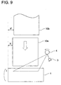
- the correction of the image writing-position is the control to change the start position of writing by the writing means 3, 4 corresponding to the end positions X, X' when the recording materials 10a and 10b are supplied onto the photoreceptor 1 respectively with the end positions X, X', as shown in Fig. 9, and controlled as described above, by the automatic writing-position determination means.
- An image forming apparatus, in which the automatic writing-position determination means is assembled, is disclosed in, for example, Japanese Patent No. 2550558, or Japanese Tokuganhei No. 11-77728 specification.
- the image forming apparatus disclosed in Japanese Patent No. 2550558 detects the offset of the recording material by a plurality of detection elements, and according to the detection result, corrects the position of the image data on a memory, and because the resolving power of the offset detection is corresponding to the number of the detection elements, the resolving power of the offset detection is limited, however, the image forming apparatus, disclosed in Japanese Tokuganhei No.
- the resolving power of the end position detection means is matched with that of the writing means, and the high accuracy offset correction equal to the resolving power of the writing means can be conducted, however, when the automatic writing-position determination means is actually used, there are various problems.
- the image position in the main scanning direction at the time of writing is controlled by adjusting the writing start position in the main scanning direction of the writing by the laser, and in the sub-scanning direction, it is controlled by adjusting the timing of the conveyance of the recording material and writing.
- the position of the writing start in the main scanning direction is determined by the calculation from the offset information from the end position detection means and the information of the size of the recording material, however, the recording materials used for the image formation are various in the size and the kind, and because there is a case in which the detection of the position of the recording material is difficult, and also a case in which the recording material with the irregular type size apart from the regular type size is used, there is a case where the offset correction by the automatic end position detection means is difficult or highly reliable offset correction is not conducted.
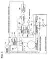
- Fig. 1 is a block diagram showing an example of the electric structure of an image forming apparatus of an embodiment of the present invention.
- Fig. 2 is a block diagram showing an example of the detailed electric structure of a main portion of the image forming apparatus of the embodiment of the present invention.
- Fig. 3 is a side sectional view showing the mechanical structure of the image forming apparatus of the embodiment of the present invention.
- a copier will be described as the image forming apparatus.
- the first sheet of the document fed through a roller 12a and roller 12b is conveyed rotationally through a roller 13.
- an image reading section 20 is structured by an optical system having a light source 23, mirrors 24, 25 and 26, image forming optical system 27 and CCD 28, and an optical system driving means, not shown.
- the reading is conducted under the condition that the light source 23 and the mirror 24 are fixed under the second platen glass 22.
- the image data of the read-out document d is set from the CCD 28 to an image processing section 120, not shown.
- the image data read out by the image reading section 20 is compressed and stored in an image memory, after the predetermined image processing is conducted in the image processing section 120.
- a recording material p is fed by a conveyance roller 181 from sheet feed cassettes 30A, 30B, and 30C, as the sheet feeding means in which the recording material is stacked, and fed to an image forming section 50. Further, the recording sheet p is fed from a hand feeding sheet feed tray 31, as a sheet feed means, by a conveyance roller 183, and fed to the image forming section 50.
- the recording material p fed to the image forming section 50 is in timed relationship with a register roller 185 as the conveyance means near its entrance, the recording material p comes close to a photoreceptor drum 51 which is an image carrier. That is, the first conveyance path from the sheet feed cassette 30 to the register roller 185, and the second conveyance path from the hand feeding sheet feed tray 31 to the register roller 185, are provided.
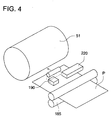
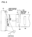
- leading edge of the recording material p in timed relationship with the register roller 185 is detected by a leading edge detection sensor 190, and the passing position in the main scanning direction is detected by a position sensor 220 structured by a close contact type line sensor. Incidentally, the detection of the passing position will be detailed later.
- the image data is inputted from the image processing section to the image writing section 40, and the laser light corresponding to the image data is irradiated from a laser diode in a image writing section 40 onto the photoreceptor drum 51, and an electrostatic latent image is formed.
- an electrostatic latent image is formed on the photoreceptor drum 51.
- This toner image is transferred onto the recording material p by a transfer section 54, which forms the transfer position, that is, an image forming position to form the toner image on the recording material p, just below the photoreceptor drum 51. Then, the recording material p in contact with the photoreceptor drum 51 is separated by a separation section 55. The recording material p separated from the photoreceptor drum 51 enters into a fixing section 59 through a conveyance mechanism 58, and the toner image is fixed by the heat and pressure. In the manner described above, the image is formed on the recording material p.
- the recording material p on which the toner image is fixed is conveyed downward and enters into a reversal section 63.
- the recording material p entered in the reversal section 63 is fed again by the reversal roller, and sent again to the image forming section 50 through a reversal conveyance path 64.
- the toner adhered to the photoreceptor drum 51 is removed by a cleaning section 56, and the photoreceptor drum 51 is ready for the next image formation.
- the other side (the surface on which the image is not yet formed) of the recording material p is conveyed into the image forming section 50, and the image is formed.
- the recording material p separated from the photoreceptor drum 51 by the separation section 55 enters again into the fixing section 59 through the conveyance mechanism 53 and is fixed. In this manner, the recording material p, on whose rear side and front side the image formation is completed, or the recording material p, on whose one side the image formation is completed, is delivered to the outside of the apparatus.
- numeral 110 is a CPU which is a control means for controlling each section of the image forming apparatus, and for controlling the passing position detection of the recording material p in the present embodiment and the determination of the writing-position.
- Numeral 120 is an image processing section which receives the information of the writing-position determined by the CPU 110 and controls for displacing the writing-position in the main scanning direction.
- Numeral 130 is a writing section which receives the processed result in the image processing section 120, and conducts the writing of the image onto the photoreceptor drum 51 by the laser beam.
- a processing section 100 composed of the CPU 110, image processing section 120 and writing section 130, is located on a main circuit board.
- numeral 210 is a sensor drive clock generation section to generate a sensor drive clock for driving the position sensor, and is structured such that the drive of the position detection sensor and the measurement of the passing position of the recording material are conducted by the sensor drive clock.
- Numeral 220 is a position sensor structured by the close contact type line sensor driven by the sensor drive clock, and is structured by an LED light source 220a which is a light emitting section, and a line sensor 220b which is a light receiving section.
- the LED light source 220a When a red LED is used as the LED light source 220a, because the responsibility becomes good, it is preferable. Further, a reading sensor of a facsimile device can be used as the light receiving section 220b. Incidentally, in the LED light source 220a and the light receiving section 220b, the light emitting element and the light receiving element may not correspond to each other by 1 to 1.
- Numeral 230 is a sample hold circuit which synchronizes the output of the position sensor 220 with the sensor drive clock and samples and holds it.
- Numeral 240 is a comparator to compare the hold result of the sample hold circuit 230 to a predetermined value (recording material detection level).
- Numeral 250 is a counter to count the sensor drive clock when the output of the comparator 240 is in the predetermined condition.
- Numeral 260 is a serial transmission section which converts the count result of the counter 250 into the predetermined serial data, and transmits it by the serial communication.
- the sensor drive clock generation section 210, sample hold circuit 230, comparator 240, counter 250, and serial transmission section 260 are arranged in the vicinity of the position sensor 220, and the position sensor 220, sample hold circuit 230 and comparator 240 structure the end position detection means.
- numeral 320 is a drive source (drive motor) to drive the register roller 185, and controlled by a drive motor ON/OFF signal from the CPU 110.
- Numeral 330 is a clutch as a transmission mechanism to transmit the rotational force of the drive motor 320 to the register roller 185 according to a register roller ON signal from the CPU 110.
- leading edge detection sensor 190 and the position sensor 220 may be located on the same side as the recording material p, or may be located on both sides so as to sandwich the recording material p.
- leading edge detection sensor 190 and the position sensor 220 are equipped above the conveyance surface of the recording material p, considering the influences of the paper powder, etc.
- Fig. 6 is a time chart showing the operation condition of the present embodiment
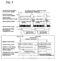
- Fig. 7 is a time chart showing further detailed condition.
- Fig. 6 is shown on the supposition that the L level becomes an active condition.
- the drive motor ON/OFF signal is turned ON-status by the CPU 110, in order to drive the drive motor 320 (Fig. 6(a)(1)).
- the register roller ON/OFF signal is turned ON-status so as to start the rotation of the register roller 185 (Fig. 6(b)(2)), and the driving force is supplied to the clutch 330. Thereby, the recording material p starts to be conveyed toward the photoreceptor drum 51.
- the LED light source 220 is also driven so as to start the light emission, by the ON of the register roller ON/OFF signal. Further, the sensor drive clock generation section 210 starts to generate the sensor drive clock, by the ON of the register roller ON/OFF signal (Fig. 6 (c)(3)).
- the recording material p is conveyed by the drive of the register roller 185 and is detected by the leading edge detection sensor 190 (Fig. 6 (d)(4)).
- the passing position of the recording material p in the main scanning direction is detected as an absolute position by the position sensor 220 located at a position whose phase is almost the same as the leading edge detection sensor 190.
- the irradiation light from the LED light source 220a is reflected by the recording material p to the position of the end portion in the main scanning direction of the recording material p, and detected by the light receiving section 220b.
- the serial transmission section 260 transmits the count result of the counter 250 showing the position of the end portion of the recording material p to the CPU 110 as the transfer position data by the serial communication.
- the comparator output pulse (Fig. 6(e)(5)) after the predetermined time after the leading edge detection sensor 190 detects the recording material p is counted by the counter 250.
- the CPU 110 which received the transfer position data gives the indication data to shift the image in the main scanning direction to the image processing section 120.
- the image processing section 120 shifts the image data in the main scanning direction by a necessary amount, and supplies the image data to the writing section 130.
- the shift of the data as described above can be met in such a manner that, as shown in Fig. 8, the an area in which the image data is actually written, is shifted in the image writing area in the main scanning direction of the image memory.
- the reference position adjustment value is a value for the adjustment between the detection result by the position detection sensor and the laser writing point.
- the passing position of the recording material p in the main scanning direction is detected by the position sensor 220 as an absolute position, and the writing-position is determined according to the detection result, the stable image formation by the determination of the correct writing-position can be conducted notwithstanding the passing position or size of the recording material p.
- the passing position of the recording material p in the main scanning direction is detected by the position sensor 220 structured by the close contact type line sensor as an absolute position, and the writing-position is determined according to the detection result, the stable image formation by the determination of the more correct writing-position than the conventional one, can be conducted notwithstanding the passing position or size of the recording material p.
- the stable image formation can be conducted by counting the clocks, notwithstanding the passing position or size of the recording material p.
- the detection resolving power of the close contact type line sensor to more than 0.25 mm, the accuracy of about 100 dpi can be obtained, thereby, the stable image formation can be conducted due to the determination of the correct writing-position, notwithstanding the passing position or size of the recording material p.
- the detection resolving power of the close contact type line sensor is made to integer times of the writing resolving power or the inverse number of integer times, the accuracy proportional to the writing resolving power is obtained, thereby, the stable image formation can be conducted due to the determination of the correct writing-position, notwithstanding the passing position or size of the recording material p.
- the position sensor 220 is located on the downstream side of the register roller 185, the sheet skew is corrected, and determination of the correct writing-position can be made corresponding to the final passing position of the recording material p, thereby, the correct and stable image formation can be conducted.
- the lighting of the LED light source 220a of the close contact type line sensor is in timed relationship with the drive of the register roller 185, the passing position of the recording material p can be detected without useless condition, and determination of the correct writing-position can be conducted, thereby, the correct and stable image formation can be conducted.
- the lighting of the LED light source 220a of the close contact type line sensor is driven by using the clock by which the lighting is outputted during the drive of the register roller 185, thereby, the stable image formation can be conducted without generating unnecessary clock.
- the close contact type line sensor (refer to Fig. 4 and Fig. 5) for a range in which at least one end of the recording material p of the maximum size and one end of the recording material p of the minimum size are covered, the stable image formation can be conducted due to the determination of the correct writing-position, notwithstanding the passing position or size of the recording material p.
- the close contact type line sensor may be arranged according to the maximum prospect amount of the passing position.
- X corresponds to the transfer position data.
- the passing position of the recording material p is detected at a predetermined timing after the leading edge of the recording material p is detected, the position in the condition that the recording material p actually passes, can be correctly detected, thereby, the stable image formation can be conducted due to the determination of the correct writing-position, notwithstanding the passing position or size of the recording material p.
- the sensor output is made sample-hold, and compared to a predetermined value, and the sheet end portion of the recording material p is detected, the position in a condition that the recording material p is actually passing can be correctly detected, thereby, the stable image formation can be conducted due to the determination of the correct writing-position, notwithstanding the passing position or size of the recording material p.
- the position in a condition that the recording material p is actually passing can be correctly detected, thereby, the stable image formation can be conducted due to the determination of the correct writing-position, notwithstanding the passing position or size of the recording material p.
- the counter 250 to detect the passing position of the recording material p is arranged in the vicinity of the position sensor 220, a wiring having a possibility of the noise generation is very short. Then, because the output of the comparator 240 which is the detection result, is transmitted by a serial communication, the data can be transmitted even when the number of wiring is small, and in a portion in which the length of the wiring is long, a possibility of the noise generation can be decreased.
- the stable image formation can be conducted due to the determination of the correct writing-position, notwithstanding the passing position or size of the recording material p.
- the automatic offset correction is conducted on the offset of the recording material p.
- the control of the writing-position in the embodiment of the present invention will be described.
- the image is formed always at an appropriate position, and even in the case where the recording sheet deviates from its regular position and conveyed, the control of the writing-position is conducted so that the image position does not deviate from its regular position.
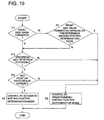
- Fig. 10 is a flow chart of the control of the writing-position in the embodiment 1.
- F5 and F6 in Fig. 10 there are cases in which the control of the writing-position is conducted by the automatic writing-position determination described above, and it is conducted without depending on the automatic writing-position determination.
- the automatic writing-position determination is as described above, and the case in which the writing-position is controlled without depending on the automatic writing-position determination, will be described later.
- the control of the writing-position is conducted by the automatic writing-position determination mode in F5, and when it can riot be conducted, the control of the writing-position is conducted by a predetermined writing-position determination mode in F6.
- each size recording material of p1, p2, p3, and p4 is position controlled so that the center lines of them coincide with each other, and conveyed in the direction shown by W. Accordingly, the end position of the width direction (the direction shown by Z in the drawing) of the recording material p is different depending on each size, and the writing start position in the main scanning direction at the time of writing is also different depending on each size. As described above, because the writing-position is different depending on the size of the recording material p, it is necessary that the size of the recording material p is grasped for the determination of the writing-position.
- the size of the recording material p is detected according to the information obtained by detecting the length in the width direction of the recording material p by the detection mechanism shown in Fig. 12.
- numeral 32 is a side edge regulation plate which is provided on the sheet feed cassette 30 and manual feeding sheet feed tray 31, and can be moved in the Y direction, and the position of the side edge regulation plate 32 is converted into the change of the voltage by the resistance 33, and the length of the width direction of the recording material p is detected. It is difficult that such the size detection mechanism is made highly accurate, and it is difficult that the difference in the length of the recording material p in mm unit is grasped.
- the discrimination of the regular size such as the sizes in A series, B series, or inch series is fully possible by the size detection mechanism shown in Fig. 12, however, it is not in smaller cases that the discrimination of the size out of the regular size is, from the above reason, difficult in the detection by the size detection mechanism shown in Fig. 12. That is, there is a case in which the detection of the size in the case of the irregular size can not be conducted.
- a sheet feed section into which the irregular size recording material p is loaded is specified.
- the manual feeding sheet feed tray 31 is specified as the sheet feed section into which the irregular size recording material p can be loaded.
- the recording material other than the regular size recording material p can not be loaded.
- the CPU 110 which is an automatic selection means for selecting the automatic position determination mode or the predetermined position determination mode from the using sheet feed means, controls the writing-position by the automatic writing-position determination of F5 when the recording material p is fed from the sheet fed cassette 30A, 30B or 30C, and when the recording material p is fed from the manual feeding sheet feed tray 31, the writing-position is controlled by the predetermined writing-position determination of F6.
- the judgement according to the information of such the sheet feed means is conducted. It is of course possible that any one of sheet feed cassette 30A, 30B or 30C is also set to the sheet fed section of the irregular size recording material.
- the irregular size mode is set from the setting section 70 of the image forming apparatus, and the writing correction without depending on the automatic writing-position determination of F6 is conducted by the setting.
- the CPU 110 selects the control means of the writing-position corresponding to the setting of the mode in the setting section 70.
- the setting section 70 structures the manual selection means.
- the recording material p is the transparent sheet or the sheet on which the framework or line is printed, it is judged as N in F4 and the control of the writing-position by the automatic writing-position determination is not conducted, and F6 is selected.
- the setting section 70 structures the manual selection means.
- the sensor to detect that the recording material p is the transparent sheet is provided on the sheet feed means, and the judgement of F4 may be conducted by the signal from the sensor.
- the sensor to detect the transparent sheet structures the discrimination means, and the CPU 110 to select the writing-position determination mode according to the sensor structures the automatic selection means.
- the sensor detects that the end position of the recording material p deviates more than a predetermined value (for instance, ⁇ 4 mm) from the original passage position of the recording material p, it is also applicable that the recording material p is judged as the transparent sheet or the sheet with a framework, and the writing-position is controlled by the predetermined writing-position determination, instead of the automatic writing-position determination.
- a predetermined value for instance, ⁇ 4 mm
- the control of the writing-position of F6 by the predetermined writing-position determination mode is conducted (Y in F2).
- the selection of such the writing-position determination mode is conducted by the CPU 110, and the CPU 110 structures the automatic selection means.
- the specific sheet mode is provided, and by selecting the specific sheet mode in the setting section 70 of the image forming apparatus, as the writing-position, the writing-position provided for the specific sheet is set.
- the regular processing mode when the control of the regular size which is closest to the irregular size is applied, the image formation with the variation of the image position within the allowable range can be conducted. Accordingly, for the irregular size recording material p, when the mode to form the image by the regular size processing is provided, by selecting the mode, the control of the writing-position set for each size can also be conducted.
- this mode is called the regular processing mode, the regular processing mode conducts the processing to allot the continuous size data obtained by, for example, the detection mechanism shown in Fig. 12, to the regular size such as p1, p2, p3 or p4, for example, as shown in Fig. 11.
- the writing-position is determined according to the size data allotted in this manner.
- the offset in the conveyance of the recording sheet shows a specific inclination depending on each image forming apparatus. Further, there is a case where such the inclination shows a specific inclination depending on each sheet feed section in the image forming apparatus. Furthermore, there is also a case where a specific inclination is shown depending on each size of the recording material p.
- the offset data of the recording material p is stored in the non-volatile memory provided in the image forming apparatus, and each kind of the above inclinations are calculated by the statistical processing, and according to the calculation result, the correction of the writing-position can be conducted.
- a method in which the optimum correction value is simply obtained from the offset data in the previous predetermined number of the image forming processes, can be adopted.
- the selection of any one of the above (a), (b) or (c) is conducted according to the judgement in F1 - F3.
- the control to determine at the writing-position specified to the specific sheet feed section is conducted.
- the OHP sheet is used, the size of the recording material to be used is set from the setting section 70, and the control to determine at the writing-position specified to the set size is conducted.
- the correction to the automatic writing-position determination as described above is conducted, and the control of trigger of the end position detection means 200 is conducted, which will be described below, thereby, the reliability of the offset detection is increased.
- the end position detection means 200 is triggered, however, in the case of the small sized recording material such as the post card size, or in the case of the transparent sheet for the OHP, there is a case where the leading edge detection sensor 190 can not detect the leading edge of the recording material p.
- the end position detection means 200 is triggered not by the leading edge detection signal of the leading edge detection sensor 190, but by the time set by a timer which starts at the specific stage in the conveyance process of the recording material p. That is, as shown by (6) in Fig.
- the register roller 185 is an example of a synchronous conveyance means which is in timed relationship with the image formation on the photoreceptor drum 51 and conveys the recording material p.
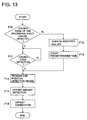
- Fig. 13 is a flow chart of such the trigger control of the end position detection means 200.
- the leading edge detection sensor 190 judges whether the leading edge detection can be detected. This judgement is conducted by the size detection of the recording material p, or according to the information of the kind of the recording material p. That is, when the size of the recording material p is small like as the post card, or the recording material p is the transparent sheet like as the OHP sheet, N is judged in F10, and in the other case, Y is judged.
- the end position detection means 200 As described above, for the recording material p whose leading edge can not be detected like as the post card or OHP sheet, because the end position detection means 200 is triggered according to ON of the register roller 185, the end position detection means 200 operates correctly notwithstanding the size and kind of the recording material p.
- the control of the writing-position by the automatic writing-position determination and the control of the writing-position not depending on the automatic writing-position determination are automatically selected, the control of the image position to form the image always at a correct position on the recording material is automatically conducted, thereby, the image forming apparatus which is easily used, is realized.
- the automatic writing-position determination function can be turned OFF manually when necessary, the mis-operation is prevented, and the image forming apparatus having the highly reliable image position control function is realized.
- the image can be formed always at a correct position.
- the image can be formed at an adequate position.
- the image can be formed at a correct position.
- the image is formed on two-sides of the front and rear of the recording material, by combining the processing in the front side image formation and the rear side image formation with each other for the control of the image position, the possibility that the difference is generated between the image positions of the front side and the rear side, is lowered, thereby, the good quality image can be effectively obtained.
- the image can be formed at an appropriate position, when the correction of the writing-position by the offset correction is not effective.
- the image can be formed at an appropriate position, when the correction of the writing-position by the offset correction is not effective.
- the end position detection means is correctly operated for all of various kinds of sizes of the recording materials, thereby, the highly reliable automatic writing-position determination can be conducted.
- the operation mode can be set in the end position detection means, the mis-operation of the automatic writing-position determination apparatus can be securely prevented.
- the end position detection means for controlling the image position can be normally functioned.
- the end position detection means for controlling the image position can be normally functioned, and further, the automatic image position determination mode can be released, thereby, the mis-operation can be securely prevented.
- the end position detection means is normally operated, and for various sizes and kinds of recording materials, the automatic image position determination function is correctly operated.
Landscapes
- Engineering & Computer Science (AREA)
- Multimedia (AREA)
- Signal Processing (AREA)
- Control Or Security For Electrophotography (AREA)
- Facsimiles In General (AREA)
- Exposure Or Original Feeding In Electrophotography (AREA)
Applications Claiming Priority (2)
| Application Number | Priority Date | Filing Date | Title |
|---|---|---|---|
| JP30243899A JP2001125440A (ja) | 1999-10-25 | 1999-10-25 | 画像形成装置 |
| JP30243899 | 1999-10-25 |
Publications (2)
| Publication Number | Publication Date |
|---|---|
| EP1096780A2 true EP1096780A2 (de) | 2001-05-02 |
| EP1096780A3 EP1096780A3 (de) | 2002-05-29 |
Family
ID=17908943
Family Applications (1)
| Application Number | Title | Priority Date | Filing Date |
|---|---|---|---|
| EP00123120A Withdrawn EP1096780A3 (de) | 1999-10-25 | 2000-10-25 | Bilderzeugungsgerät |
Country Status (3)
| Country | Link |
|---|---|
| US (1) | US6473112B1 (de) |
| EP (1) | EP1096780A3 (de) |
| JP (1) | JP2001125440A (de) |
Cited By (5)
| Publication number | Priority date | Publication date | Assignee | Title |
|---|---|---|---|---|
| EP1582367A1 (de) * | 2004-03-31 | 2005-10-05 | Brother Kogyo Kabushiki Kaisha | Seriendrucker mit Druckmediumserkennungsfunktion |
| EP1541351A4 (de) * | 2002-09-09 | 2007-10-03 | Seiko Epson Corp | Flüssigkeitsausstossvorrichtung, rechnersystem und flüssigkeitsausstossverfahren |
| US7841589B2 (en) * | 2005-12-14 | 2010-11-30 | Canon Kabushiki Kaisha | Image forming apparatus |
| US8141992B2 (en) | 2006-03-24 | 2012-03-27 | Seiko Epson Corporation | Liquid storage container |
| US8646866B2 (en) | 2002-08-08 | 2014-02-11 | Seiko Epson Corporation | Recording apparatus, recording method, program, and computer system |
Families Citing this family (7)
| Publication number | Priority date | Publication date | Assignee | Title |
|---|---|---|---|---|
| JP2003248410A (ja) | 2001-12-18 | 2003-09-05 | Canon Inc | 画像形成装置および画像形成制御方法 |
| JP2004145504A (ja) | 2002-10-23 | 2004-05-20 | Keyence Corp | 画像処理システム |
| JP4483227B2 (ja) * | 2003-08-22 | 2010-06-16 | 富士ゼロックス株式会社 | 画像形成装置 |
| JP2007078875A (ja) * | 2005-09-12 | 2007-03-29 | Canon Inc | 画像形成装置および記録材搬送方法 |
| JP5799573B2 (ja) * | 2011-05-12 | 2015-10-28 | 富士ゼロックス株式会社 | 画像形成装置および記録材処理装置 |
| JP5962494B2 (ja) * | 2012-12-20 | 2016-08-03 | 富士ゼロックス株式会社 | 画像形成装置、媒体の搬送装置および媒体の収容容器 |
| JP2016099522A (ja) * | 2014-11-21 | 2016-05-30 | キヤノン株式会社 | 印刷装置、印刷装置の制御方法、プログラム、及び記憶媒体 |
Family Cites Families (8)
| Publication number | Priority date | Publication date | Assignee | Title |
|---|---|---|---|---|
| JPS62254160A (ja) * | 1986-04-28 | 1987-11-05 | Toshiba Corp | 画像形成装置 |
| JPS63149670A (ja) * | 1986-12-15 | 1988-06-22 | Ricoh Co Ltd | 画像書込み位置補正方法 |
| JPS63236071A (ja) * | 1987-03-25 | 1988-09-30 | Ricoh Co Ltd | 横レジスト調整装置 |
| JPH04147874A (ja) * | 1990-10-11 | 1992-05-21 | Ricoh Co Ltd | 画像記録装置 |
| WO1995013678A1 (de) | 1993-11-12 | 1995-05-18 | Siemens Nixdorf Informationssysteme Ag | Vorrichtung und verfahren zur exakten positionierung eines druckbildes auf einem aufzeichnungsträger |
| JP3667788B2 (ja) | 1994-07-06 | 2005-07-06 | シャープ株式会社 | 画像形成装置 |
| JPH08230231A (ja) * | 1995-03-01 | 1996-09-10 | Ricoh Co Ltd | デジタル画像形成装置 |
| JP3492071B2 (ja) * | 1996-02-23 | 2004-02-03 | 株式会社リコー | 画像記録装置 |
-
1999
- 1999-10-25 JP JP30243899A patent/JP2001125440A/ja active Pending
-
2000
- 2000-10-23 US US09/694,749 patent/US6473112B1/en not_active Expired - Lifetime
- 2000-10-25 EP EP00123120A patent/EP1096780A3/de not_active Withdrawn
Cited By (12)
| Publication number | Priority date | Publication date | Assignee | Title |
|---|---|---|---|---|
| US8646866B2 (en) | 2002-08-08 | 2014-02-11 | Seiko Epson Corporation | Recording apparatus, recording method, program, and computer system |
| EP1541351A4 (de) * | 2002-09-09 | 2007-10-03 | Seiko Epson Corp | Flüssigkeitsausstossvorrichtung, rechnersystem und flüssigkeitsausstossverfahren |
| US7537302B2 (en) | 2002-09-09 | 2009-05-26 | Seiko Epson Corporation | Liquid ejecting apparatus, computer system, and liquid ejecting method |
| US7717536B2 (en) | 2002-09-09 | 2010-05-18 | Seiko Epson Corporation | Liquid ejecting apparatus, computer system, and liquid ejection method |
| CN101264691B (zh) * | 2002-09-09 | 2010-06-23 | 精工爱普生株式会社 | 液体喷射装置、计算机系统 |
| US8136915B2 (en) | 2002-09-09 | 2012-03-20 | Seiko Epson Corporation | Liquid ejecting apparatus, computer system, and liquid ejection method |
| US8672442B2 (en) | 2002-09-09 | 2014-03-18 | Seiko Epson Corporation | Liquid ejecting apparatus, computer system, and liquid ejection method |
| EP1582367A1 (de) * | 2004-03-31 | 2005-10-05 | Brother Kogyo Kabushiki Kaisha | Seriendrucker mit Druckmediumserkennungsfunktion |
| US7246957B2 (en) | 2004-03-31 | 2007-07-24 | Brother Kogyo Kabushiki Kaisha | Serial printer with print-medium detecting function |
| CN100352663C (zh) * | 2004-03-31 | 2007-12-05 | 兄弟工业株式会社 | 具有打印介质探测功能的串行打印机 |
| US7841589B2 (en) * | 2005-12-14 | 2010-11-30 | Canon Kabushiki Kaisha | Image forming apparatus |
| US8141992B2 (en) | 2006-03-24 | 2012-03-27 | Seiko Epson Corporation | Liquid storage container |
Also Published As
| Publication number | Publication date |
|---|---|
| US6473112B1 (en) | 2002-10-29 |
| JP2001125440A (ja) | 2001-05-11 |
| EP1096780A3 (de) | 2002-05-29 |
Similar Documents
| Publication | Publication Date | Title |
|---|---|---|
| CN100368939C (zh) | 成像设备和成像控制方法 | |
| US7646479B2 (en) | Recording medium discrimination apparatus and method | |
| US6788322B2 (en) | Image forming apparatus that accurately detects sheet in the feeding direction, and method thereof | |
| US6473112B1 (en) | Image forming apparatus | |
| US6340984B1 (en) | Image forming apparatus for correcting an angle of inclination of the recording material and for recording corrected image | |
| JP2003330334A (ja) | 画像形成装置および画像形成制御方法 | |
| JP4343558B2 (ja) | 画像形成装置 | |
| EP1039739B1 (de) | Schreibkontrollverfahren und Bilderzeugungsgerät | |
| US5648843A (en) | Automatic duplex image forming apparatus having an adjusting driving mechanism | |
| US6687471B2 (en) | Image forming apparatus | |
| JP4129589B2 (ja) | 画像形成装置 | |
| US6259868B1 (en) | Image forming apparatus with width detection | |
| JPH1032682A (ja) | 複写装置及びその原稿斜行補正方法 | |
| JPH09219776A (ja) | 画像形成装置 | |
| JP2000335010A (ja) | 書き込み制御方法および画像形成装置ならびにセンサ | |
| JP4801384B2 (ja) | 画像形成装置 | |
| JP2915925B2 (ja) | 画像形成装置の制御方法 | |
| JP4147838B2 (ja) | 画像形成装置 | |
| JP2001228778A (ja) | 画像形成装置 | |
| JP7351147B2 (ja) | 画像形成装置 | |
| JPH10203691A (ja) | シート搬送方法及び該方法を用いたシート搬送装置及び画像読取装置及び画像形成装置 | |
| JP2003134309A (ja) | 画像形成装置 | |
| JP2001166663A (ja) | 画像形成装置 | |
| JP2002248804A (ja) | 画像形成装置 | |
| JP2004080067A (ja) | 画像処理装置 |
Legal Events
| Date | Code | Title | Description |
|---|---|---|---|
| PUAI | Public reference made under article 153(3) epc to a published international application that has entered the european phase |
Free format text: ORIGINAL CODE: 0009012 |
|
| AK | Designated contracting states |
Kind code of ref document: A2 Designated state(s): AT BE CH CY DE DK ES FI FR GB GR IE IT LI LU MC NL PT SE |
|
| AX | Request for extension of the european patent |
Free format text: AL;LT;LV;MK;RO;SI |
|
| PUAL | Search report despatched |
Free format text: ORIGINAL CODE: 0009013 |
|
| AK | Designated contracting states |
Kind code of ref document: A3 Designated state(s): AT BE CH CY DE DK ES FI FR GB GR IE IT LI LU MC NL PT SE |
|
| AX | Request for extension of the european patent |
Free format text: AL;LT;LV;MK;RO;SI |
|
| AKX | Designation fees paid | ||
| REG | Reference to a national code |
Ref country code: DE Ref legal event code: 8566 |
|
| STAA | Information on the status of an ep patent application or granted ep patent |
Free format text: STATUS: THE APPLICATION IS DEEMED TO BE WITHDRAWN |
|
| 18D | Application deemed to be withdrawn |
Effective date: 20021130 |