EP1097732B1 - Fixation pour planche de glisse, notamment snowboards - Google Patents
Fixation pour planche de glisse, notamment snowboards Download PDFInfo
- Publication number
- EP1097732B1 EP1097732B1 EP01103539A EP01103539A EP1097732B1 EP 1097732 B1 EP1097732 B1 EP 1097732B1 EP 01103539 A EP01103539 A EP 01103539A EP 01103539 A EP01103539 A EP 01103539A EP 1097732 B1 EP1097732 B1 EP 1097732B1
- Authority
- EP
- European Patent Office
- Prior art keywords
- locking
- binding
- binding according
- boot
- snowboard
- Prior art date
- Legal status (The legal status is an assumption and is not a legal conclusion. Google has not performed a legal analysis and makes no representation as to the accuracy of the status listed.)
- Expired - Lifetime
Links
- 230000027455 binding Effects 0.000 title claims description 130
- 238000009739 binding Methods 0.000 title claims description 130
- 230000001419 dependent effect Effects 0.000 claims description 2
- 230000007246 mechanism Effects 0.000 claims 1
- 238000003780 insertion Methods 0.000 description 3
- 230000037431 insertion Effects 0.000 description 3
- 238000013459 approach Methods 0.000 description 2
- 238000006073 displacement reaction Methods 0.000 description 2
- 230000000694 effects Effects 0.000 description 2
- 238000004091 panning Methods 0.000 description 2
- 238000012549 training Methods 0.000 description 2
- 229910000831 Steel Inorganic materials 0.000 description 1
- 230000008275 binding mechanism Effects 0.000 description 1
- 238000010276 construction Methods 0.000 description 1
- 238000013461 design Methods 0.000 description 1
- 238000011161 development Methods 0.000 description 1
- 230000018109 developmental process Effects 0.000 description 1
- 230000009365 direct transmission Effects 0.000 description 1
- 230000005489 elastic deformation Effects 0.000 description 1
- 239000000463 material Substances 0.000 description 1
- 238000012986 modification Methods 0.000 description 1
- 230000004048 modification Effects 0.000 description 1
- 230000000149 penetrating effect Effects 0.000 description 1
- 230000036316 preload Effects 0.000 description 1
- 229910001220 stainless steel Inorganic materials 0.000 description 1
- 239000010935 stainless steel Substances 0.000 description 1
- 239000010959 steel Substances 0.000 description 1
- 230000007704 transition Effects 0.000 description 1
Images


Classifications
-
- A—HUMAN NECESSITIES
- A63—SPORTS; GAMES; AMUSEMENTS
- A63C—SKATES; SKIS; ROLLER SKATES; DESIGN OR LAYOUT OF COURTS, RINKS OR THE LIKE
- A63C10/00—Snowboard bindings
- A63C10/02—Snowboard bindings characterised by details of the shoe holders
- A63C10/10—Snowboard bindings characterised by details of the shoe holders using parts which are fixed on the shoe, e.g. means to facilitate step-in
-
- A—HUMAN NECESSITIES
- A63—SPORTS; GAMES; AMUSEMENTS
- A63C—SKATES; SKIS; ROLLER SKATES; DESIGN OR LAYOUT OF COURTS, RINKS OR THE LIKE
- A63C10/00—Snowboard bindings
- A63C10/02—Snowboard bindings characterised by details of the shoe holders
- A63C10/08—Toe or heel stirrups; Clamps
-
- A—HUMAN NECESSITIES
- A63—SPORTS; GAMES; AMUSEMENTS
- A63C—SKATES; SKIS; ROLLER SKATES; DESIGN OR LAYOUT OF COURTS, RINKS OR THE LIKE
- A63C10/00—Snowboard bindings
- A63C10/02—Snowboard bindings characterised by details of the shoe holders
- A63C10/10—Snowboard bindings characterised by details of the shoe holders using parts which are fixed on the shoe, e.g. means to facilitate step-in
- A63C10/106—Snowboard bindings characterised by details of the shoe holders using parts which are fixed on the shoe, e.g. means to facilitate step-in to the front and back of the shoe
Definitions
- the invention relates to a binding specifically for a snowboard binding.
- Snowboard bindings are known and exist in their usual form today a front binding element and a rear binding element, from which the front binding element forms a bow from a spring wire in the the boot used (hard boot) with a protruding part of the front end his boot sole is insertable.
- the rear binding element also exists from an elastically deformable spring wire bow. On this is a tension or Swiveling over dead center lever provided with the boot fixed in the binding this on a part of the sole of the boot protruding from the heel or heel area reaches behind and thereby fixes the boot in the binding.
- ski bindings two jaws are known as the rear binding element to provide (WO 80/00063), the space between them for receiving a boot and form lateral contact surfaces for the boot.
- There is one in each cheek slit-shaped recess is provided, which is provided on the ski boot and laterally pin protruding from the boot is insertable.
- the recess is at one for this with the binding of the upper side of the ski facing away open.
- the Recess an oblique course such that de boots after its insertion in the Binding by a front binding element with the pin in the recesses are secured against slipping out.
- This known binding is a pure ski binding.
- a ski binding is known (EP 0 343 302 A1, on July 11, 1989 in US 4,846,492 published), in which both a front and a rear binding element two each form the ski boot between the cheeks and on both Baking each binding element each have a recess for receiving a Projection on the ski boot is provided.
- One of the two binding elements is one Axis can be swiveled transversely to the longitudinal axis of the ski and parallel to the running surface of the ski, that in an open position of the binding the ski boot in question with its Projections can be inserted into the recesses of the jaws and then the front Binding element is pivoted until it is a central in its closed position Leaf spring snaps into place.
- a snowboard binding for hard boots is known from DE 41 06 401 A1, in which the heel area of the hard boot is attached using a swivel bracket.
- the Swivel bracket is pivotally attached to a step element.
- the appearance element is formed by two elongated tabs and a step crossbar, which with the front ends of the tabs is rigidly connected.
- the rear ends of the tabs are via pivot pins on opposite sides of the basic binding structure pivotally attached.
- the front ends of the tabs each end lengthways protruding locking lug.
- the binding also has a locking slide on by means of a sliding sleeve in the basic binding structure in the longitudinal direction of the binding is movable.
- the locking slide has a locking pin on each side on.
- the locking lugs become with the tabs moved down and slide on the locking pin of the Locking slide over. This causes an axial longitudinal displacement of the Locking slide.
- the locking slide is spring-loaded, so that it moves Swiping back the locking tabs and pushing them down in the Holds position.
- the locking slide also has a cross on its front projecting handle with which he pushed forward against the spring force can be. This displacement releases the locking lugs and enables them to be released the bond to rise.
- the snowboard binding known from DE 41 06 401 A1 Snow, ice and / or dirt can collect around the sliding sleeve and the function affect the bond.
- the object of the invention is to show a snowboard binding that the boots fixed more reliably in the binding and thus easy release on the snowboard Boots from the binding.
- the snowboard binding With the snowboard binding according to the invention, it can be put on easily and conveniently or getting into the binding by the fact that the respective boot with the at least one projection in a slot-shaped recess in a rear Binding element inserted and then in this recess by one on the jaws of the Binding element provided locking element is locked. Fixing the Boots in the binding can be so without tightening the hard, the boots on the snowboard holding springs and in particular without great effort. In particular is the boot can be released from the binding without any effort.
- Support surfaces that interact with corresponding counter surfaces on the boot are checked added. These support surfaces are, for example, surfaces of the at least one Recess and / or surfaces of the jaws of the binding element outside of Recess.
- the counter surfaces are then either surfaces of the at least one Projection and / or surfaces of the boot.
- Heel or heel area of the boot on each lengthways each side of the boot has a projection formed, which is then transverse with its longitudinal extent or is perpendicular to the boot axis.
- a clamping in the invention of the boot between the front and the back Binding element always with the same and in particular also achieved with optimal strength, so that an unwanted Release of the boot from the binding by the driving dynamics is prevented.
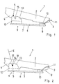
- 1 is a boot in the form of a special one Ski or snowboard boot that is in the area of its sole 2 at least on the front of the boot one of a binding element engaging edge or level 3 forms like this is also common with ski boots.
- the boot 1 has two projections 5, from each of which has a lengthwise direction of the boot Projecting side of paragraph 4.
- the projections 5 are axially transverse to one another arranged to the longitudinal axis of the boot and of a length of one penetrating the boot 1 in the area of paragraph 4
- Round rod made of a heavy-duty material, preferably made of stainless steel.
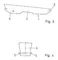
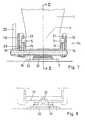
- the binding 6 consists of essentially from a base plate 7 with its underside on the top of the snowboard, not shown can be attached, on the top two binding elements are attached, namely the front binding element 8, which from a attached to the top of the base plate 7 Plate 10 with a bracket 11, and that rear bracket element 9. At least one of the two Bracket elements 8 and 9 is in the longitudinal direction of the base plate 7 adjustable to bind 6 to different shoe sizes to be able to adjust.
- Boot 1 is this by means of level 3 on the bracket 11 held and lies with the bottom of his sole 2 in Area of the front of the boot opposite the front of the boot plate 10 set backwards.
- Through this Training of the front binding element 8 are all Parts of binding with boot 1 fixed in binding 6 based on the front end of the boot backwards offset so that the binding 6 has a short length.
- the rear binding element 9 forms independently of one different design in detail two side Support jaws 13, between which a surface 12 is provided and that between them is fixed in the binding 6 Pick up boots 1 in the area of paragraph 4, i.e. at her vertical support surfaces 14 facing each other for the sides of the Form paragraph 4.
- the surface 12 is in the binding 6 arranged boot 1 at a distance from the bottom of the Sole 2 or paragraph 4 and is also sloping roof or wedge-shaped, so that any on the Underside of the clump of sticky snow when inserted of the boot 1 in the binding through the sloping roof Surface 12 is blown off.
- Each support jaw 13 also has one on the Support surface 14 and on the base plate 7 facing away Top of the support jaw open slot 15, in the to Fixing the boot 1 in the binding 6 has a projection 5 is insertable.
- a later described one Locking element 16 having binding mechanism or Locking device is each projection 5 in the associated slot 15 lockable.
- To insert the respective projection 5 into the associated one To facilitate slot 15 is the top of each Support jaw 13 at least in a partial area as an inclined surface 17 formed from the binding element 8 distal end of the binding element 9 or of the support jaw 13 running obliquely downwards in the each slot 15 opens.
- a similar sloping surface 18 is also formed on the other side of the slot 15.
- each slot 15 is inclined or sloping formed such that the longitudinal extent of this slot lies in a plane E which is in line with the plane of the base plate 7 forms an angle of less than 90 ° to that of the Binding element 8 facing away opens.
- the binding 6 allows easy connection of the snowboard with the boot 1 without excessive exertion. Since the two binding elements 8 and 9 rigid or at least in are substantially rigidly attached to the base plate 7 also a rigid, optimal guidance of the snowboard Guaranteed fixation of the boot 1 on the snowboard guaranteed.
- the rear binding element 9 can be different configured and also different on the base plate 7 be attached.
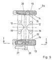
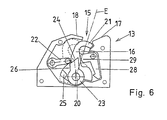
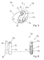
- FIGS 5 and 6 show a possible embodiment Binding element 9a, in which the two, each as a housing trained section jaws 13 via two steel brackets or bracket-like connectors 19 connected together and spaced from each other, which is also the horizontal surface 12 form. With the connecting pieces 19 is the binding element 9a, for example, screwed directly onto the base plate 7.
- the locking device exists first from the hook-shaped locking element 16, which at one end below surface 12 on a shaft 20 and is pivotable relative to this, the extends between the two support jaws 13 and in this is pivotally mounted at both ends.
- the wave 20 is located below surface 12.
- the axis of shaft 20 lies in the common plane E with the longitudinal extent the slots 15 or their central axes.
- each locking element 16 forms one hook-shaped section 21, when pivoting the locking element 16 around the axis of the shaft 22 from a, in the Fig. 6 shown with broken lines non-locking Position in which the locking element 16 or the section 21 outside the slot 15 and laterally from this is arranged, pivotable into a position in which the locking element 16 with the hook-like section 21 extends into the respective slot 15, namely in Area of the upper end of this slot and thus an im Slit 15 arranged projection 5 engages behind and thus locked against moving out of the slot 15.
- each locking element 16 which is in the unlocking position on the binding element 8 facing side of the slot 15 is located in the locking Prestressed position.
- the locking device further comprises one by one Axis parallel to the axis of the shaft 20 pivotable locking lever 22, in the locking position of the locking element 16 against one on this locking element Formed surface rests and thereby an undesirable Swiveling the locking element 16 out of the locking position prevented.
- On the shaft 20 rotatably provided a driver 23, one with the Locking lever 22 cooperating control surface 24 and one with a stop 25 on the locking element 16 cooperating counter surface 26 forms.
- One over one Support jaws 13 projecting end is on the shaft 20 Actuating lever 27 is provided. By panning this Actuating lever and thus the shaft 20 can in the locking position locking element 16 be solved. This will initially go through the control surface 24 of the locking lever 22 is pivoted so that it is the locking element 16 releases.
- a ratchet lever 28 engages behind a surface of the in the unlocking position located locking element 16 and holds this in the non-locking position.
- the pawl lever 28 has an approach 29 which protrudes into the respective slot 15.
- spring elements also not shown, provided the locking lever in a locking element 16 in the locking position securing position and the Pawl lever 28 in a locking element 16 in the Preload the non-locking position.
- Figures 11-13 show the function of the elements of the Locking device. 11 is the insertion a projection 5 in a slot 15 when unlocking Locking element 16 shown. The lead comes 5 against the approach 29 to the system, so by pivoting the Ratchet lever 28 released the locking element 16, which then locks into that shown in FIG Pivots position in which the locking element 16 also is secured by the locking lever 22.
- the binding element 9a is not absolutely rigid, but with a certain possibility of movement on the base plate 7 attached.
- the Openings 33 with their axis parallel to the longitudinal extent the base plate 7 have a cross section, which is larger than the cross section of the mandrels 32.
- a rubber buffer 34 is arranged between the intermediate plate 30 and the underside of the connecting element 19 due to elastic deformation a certain movement of the Allows binding element 9a relative to the base plate, namely by an amount equal to 32 through the play of the mandrels Openings 33 is predetermined.
- FIGS. 14 and 15 show a preferred embodiment a binding element 9b, which in turn consists of the two housing-like support jaws 13, each with a slot 15 consists.
- the locking element 16 is a Locking element 16a provided.
- the two locking elements 16a which in this embodiment is rotation-proof are held on the shaft 20, are each by a leaf spring 35 is biased into the locking position, in which each locking element 16a with its hook-like Section 21a from the housing-like support jaws 13 on the The top protrudes and outside the support jaw 13 den concerned slot 15 at its upper, open end closes and thereby one sitting in the slot 15 Latch 5 locked.
- each locking element 16a designed so that when swiveling against the Effect of the spring 35 in the non-locking position in this position with the hook-like section 21a on the Binding element 8 is opposite side of the slot 15.
- each locking element 16a has an inclined surface 36 which in a plane running parallel to the axis of the shaft 20 lies, which is an angle smaller than with the base plate 7 90 ° enclosing to the rear, i.e. to the the Binding element 8 facing away from the binding element 9b opens.
- the axis of the shaft 20 also lies in the binding element 9a and the longitudinal extent of each slot 15 in the plane E, which has the unwritten tendency.
- the binding 6a and its binding element 9b stand out through an extremely simple and therefore very reliable Construction. There is a multitude of elements in the Locking devices dispensed with. Rather, these are in the essentially on the hook-like locking elements 16a reduced.
Landscapes
- Footwear And Its Accessory, Manufacturing Method And Apparatuses (AREA)
- Pharmaceuticals Containing Other Organic And Inorganic Compounds (AREA)
- Lubricants (AREA)
- Clamps And Clips (AREA)
Claims (21)
- Fixation pour des planches de surf de neige, que l'on peut fixer sur une planche de surf et dans laquelle peut être reçue une chaussure de surf (1), comprenant deux éléments de verrouillage (16, 16a) qui sont agencés de chaque côté de la fixation, et comprenant un élément d'actionnement commun (27) couplé aux mécanismes de verrouillage (16, 16a) de telle manière qu'en faisant tourner l'élément d'actionnement (27), les éléments de verrouillage (16, 16a) peuvent être déplacés jusque dans une position non verrouillée, afin de permettre un une libération de la chaussure hors de la fixation.
- Fixation pour des planches de surf de neige selon la revendication 1, caractérisée en ce que la fixation comprend deux appuis latéraux (13) pour la chaussure de surf, chacun desdits appuis étant réalisé avec un évidement latéral (15), lesdits évidements latéraux étant mutuellement opposés, afin de recevoir des tronçons de la chaussure (5), et les éléments de verrouillage (16, 16a) coopèrent avec les évidements (15).
- Fixation pour des planches de surf de neige selon la revendication 2, caractérisée en ce que chaque évidement (15) est ouvert vers le haut et vers le côté intérieur de l'appui respectif (13).
- Fixation pour des planches de surf de neige selon l'une ou l'autre des revendications 2 ou 3, caractérisée en ce que chaque élément de verrouillage (16, 16a) est monté sur l'appui respectif (13) de manière adjacente à l'évidement respectif (15).
- Fixation pour des planches de surf de neige selon l'une au moins des revendications 2 à 4, caractérisée en ce que chaque élément de verrouillage (16, 16a) est mobile entre une position verrouillée dans laquelle un tronçon de verrouillage (21, 21a) pénètre dans l'évidement, et la position non verrouillée dans laquelle le tronçon de verrouillage (21, 21a) est disposé hors de l'évidement.
- Fixation pour des planches de surf de neige selon l'une au moins des revendications 2 à 5, caractérisée en ce que la face supérieure de chaque appui (13) est réalisée, au moins dans une zone partielle, sous forme d'une surface oblique (17) qui débouche dans l'évidement (15), de sorte que l'introduction du tronçon de chaussure (5) dans l'évidement (15) est facilitée.
- Fixation pour des planches de surf de neige selon l'une au moins des revendications précédentes, caractérisée en ce que les éléments de verrouillage (16, 16a) sont couplés à un arbre commun (20).
- Fixation pour des planches de surf de neige selon la revendication 7, caractérisée par une surface (12) entre les appuis (13), et par le fait que l'arbre (20) s'étend au-dessous de la surface (12).
- Fixation pour des planches de surf de neige selon l'une au moins des revendications précédentes, caractérisée en ce qu'il est prévu un élément de sécurité (22) afin d'empêcher un déplacement inopiné de l'élément de verrouillage (16, 16a).
- Fixation pour des planches de surf de neige selon les revendications 7 et 9 ou selon les revendications 8 et 9, caractérisée en ce que l'élément de sécurité (20) est capable de tourner autour d'un axe qui s'étend parallèlement à l'arbre (20) afin de maintenir les éléments de verrouillage (16, 16a) dans une position verrouillée lorsque l'élément d'actionnement commun (27) n'est pas actionné.
- Fixation pour des planches de surf de neige selon l'une ou l'autre des revendications 9 ou 10, caractérisée par un élément d'entraínement (23) monté sur l'arbre (20) de telle façon que lors d'un déplacement de l'élément d'actionnement (27), l'élément de sécurité (22) est tout d'abord déplacé en libérant les éléments de verrouillage (16, 16a), et les éléments de verrouillage (16, 16a) sont ensuite déplacés jusque dans la position non verrouillée lors d'une poursuite du déplacement de l'élément d'actionnement (27).
- Fixation pour des planches de surf de neige selon l'une au moins des revendications précédentes, caractérisée en ce que les éléments de verrouillage (16, 16a) sont en forme de crochet.
- Fixation pour des planches de surf de neige selon l'une au moins des revendications précédentes, prise en dépendance de la revendication 2, caractérisée en ce que chaque élément de verrouillage (16, 16a) comporte une surface de coulissement (36) afin de laisser coulisser l'élément de verrouillage (16, 16a) depuis une position verrouillée en direction de la position non verrouillée, lors d'un déplacement du tronçon de chaussure (5) jusque dans l'évidement (15).
- Fixation pour des planches de surf de neige selon l'une au moins des revendications précédentes, caractérisée en ce que chaque élément de verrouillage (16, 16a) est précontraint dans une position verrouillée.
- Fixation pour des planches de surf de neige selon la revendication 14, caractérisée en ce que chaque élément de verrouillage (16, 16a) est précontraint dans la position verrouillée par un élément à ressort (35).
- Fixation pour des planches de surf de neige selon l'une au moins des revendications précédentes, caractérisée en ce que la fixation comporte une extrémité avant et une extrémité arrière, et en ce que chaque élément de verrouillage (16, 16a) est agencé sur la fixation de telle manière que lors de son déplacement en direction de la position non verrouillée il se déplace vers l'extrémité arrière de la fixation.
- Fixation pour des planches de surf de neige selon l'une au moins des revendications précédentes, caractérisée en ce que les appuis latéraux opposés (13) sont éloignés l'un de l'autre à une distance non réglable.
- Fixation pour des planches de surf de neige selon l'une au moins des revendications précédentes, caractérisée en ce que chaque élément de verrouillage (16, 16a) est situé dans un plan, et en ce que les plans des éléments de verrouillage sont parallèles.
- Fixation pour des planches de surf de neige selon l'une au moins des revendications précédentes, caractérisée en ce que chaque élément de verrouillage (16, 16a) est fixé entre des parois opposées d'un appui correspondant.
- Fixation pour des planches de surf de neige selon l'une au moins des revendications précédentes, caractérisée à en ce qu'il est prévu un élément de maintien (28) afin de maintenir les éléments de verrouillage (16, 16a) dans la position non verrouillée, jusqu'à' la mise en place d'une chaussure (1) dans la fixation.
- Fixation pour des planches de surf de neige selon l'une au moins des revendications précédentes, caractérisée en ce que la fixation comporte une extrémité avant et une extrémité arrière, et en ce que l'élément d'actionnement (27) est agencé le long d'un côté de la fixation et s'étend entre l'extrémité avant et l'extrémité arrière.
Applications Claiming Priority (6)
| Application Number | Priority Date | Filing Date | Title |
|---|---|---|---|
| DE4304876 | 1993-02-17 | ||
| DE4304876 | 1993-02-17 | ||
| DE4311630A DE4311630C2 (de) | 1993-02-17 | 1993-04-08 | Bindungssystem für Gleitbretter, insbesondere Snowbords, sowie Stiefel zur Verwendung bei einem solchen Bindungssystem |
| DE4311630 | 1993-04-08 | ||
| EP94102188A EP0615774B1 (fr) | 1993-02-17 | 1994-02-12 | Système de fixation pour planches, notamment surf de neiges |
| EP99109643A EP0934762B1 (fr) | 1993-02-17 | 1994-02-12 | Fixation pour planche de glisse, notamment snowboard |
Related Parent Applications (1)
| Application Number | Title | Priority Date | Filing Date |
|---|---|---|---|
| EP99109643A Division EP0934762B1 (fr) | 1993-02-17 | 1994-02-12 | Fixation pour planche de glisse, notamment snowboard |
Publications (3)
| Publication Number | Publication Date |
|---|---|
| EP1097732A2 EP1097732A2 (fr) | 2001-05-09 |
| EP1097732A3 EP1097732A3 (fr) | 2001-05-23 |
| EP1097732B1 true EP1097732B1 (fr) | 2003-06-04 |
Family
ID=6480721
Family Applications (2)
| Application Number | Title | Priority Date | Filing Date |
|---|---|---|---|
| EP01103539A Expired - Lifetime EP1097732B1 (fr) | 1993-02-17 | 1994-02-12 | Fixation pour planche de glisse, notamment snowboards |
| EP99109643A Expired - Lifetime EP0934762B1 (fr) | 1993-02-17 | 1994-02-12 | Fixation pour planche de glisse, notamment snowboard |
Family Applications After (1)
| Application Number | Title | Priority Date | Filing Date |
|---|---|---|---|
| EP99109643A Expired - Lifetime EP0934762B1 (fr) | 1993-02-17 | 1994-02-12 | Fixation pour planche de glisse, notamment snowboard |
Country Status (2)
| Country | Link |
|---|---|
| EP (2) | EP1097732B1 (fr) |
| DE (4) | DE4311630C2 (fr) |
Families Citing this family (22)
| Publication number | Priority date | Publication date | Assignee | Title |
|---|---|---|---|---|
| US5890730A (en) * | 1994-08-18 | 1999-04-06 | Switch Manufacturing | Snowboard boot and binding apparatus |
| DE4416531C2 (de) * | 1994-05-06 | 1998-01-15 | F2 Int Gmbh | Snowboardbindung |
| DE9421380U1 (de) * | 1994-05-06 | 1995-10-12 | F2 International Ges.M.B.H., Kirchdorf | Snowboardbindung |
| DE4416023C1 (de) * | 1994-05-06 | 1995-10-12 | Christian Breuer | Snowboard-Bindung |
| DE4416024C1 (de) * | 1994-05-06 | 1995-10-12 | Oliver Breuer | Snowboard-Bindung |
| US6293578B1 (en) | 1994-08-18 | 2001-09-25 | Vans, Inc. | Snowboard boot and binding apparatus |
| DE4435960C2 (de) * | 1994-10-07 | 1998-05-20 | Goodwell Int Ltd | Snowboardbindung |
| US5660410A (en) * | 1994-12-09 | 1997-08-26 | Device Manufacturing Corporation | Strapless boot binding for snowboards |
| FR2732230B1 (fr) * | 1995-03-31 | 1997-05-30 | Brechet Daniel | Dispositif de liaison semi-automatique entre chaussure et planche de glisse et notamment surf de neige |
| US6123354A (en) * | 1996-05-29 | 2000-09-26 | Laughlin; James | Step-in snowboard binding |
| FR2749181B1 (fr) * | 1996-06-04 | 1998-09-11 | Salomon Sa | Dispositif de retenue d'une chaussure sur une planche de glisse, le dispositif comprenant un element d'appui dorsal articule |
| FR2749483B1 (fr) * | 1996-06-06 | 1998-09-11 | Salomon Sa | Dispositif de retenue d'une chaussure sur une planche de glisse |
| FR2754462B1 (fr) * | 1996-10-14 | 1998-11-06 | Rossignol Sa | Ensemble chaussure-fixation pour planche de glisse sur neige |
| FR2755027B1 (fr) * | 1996-10-25 | 1999-01-15 | Salomon Sa | Dispositif de retenue d'une chaussure sur une planche de glisse destinee a la pratique du surf sur la neige |
| US6270090B1 (en) * | 1997-05-06 | 2001-08-07 | Skis Rossignol S.A. | Roller skate with removable boot |
| DE19729775C1 (de) * | 1997-07-11 | 1998-12-10 | Triple L Handels Gmbh | Vorrichtung zur lösbaren Befestigung eines Stiefels am Gestell eines Roll- oder Schlittschuhs |
| FR2769844B1 (fr) * | 1997-10-16 | 2000-01-14 | Salomon Sa | Dispositif de retenue d'une chaussure sur un engin de glisse |
| US6105995A (en) * | 1998-04-02 | 2000-08-22 | Zill; Ken | Snowboard binding |
| DE19846005C1 (de) * | 1998-10-06 | 2000-05-25 | Reinhard Hansen | Stiefel-Bindungskombination |
| DE10020594A1 (de) * | 2000-04-05 | 2001-10-18 | Raichle Boots Ag Kreuzlingen | Snowboardbindung und Snowboardstiefel zum Einsatz mit einer solchen |
| US6467795B1 (en) | 2000-12-29 | 2002-10-22 | Shimano Inc. | Snowboard binding with highback |
| DE102009059968A1 (de) * | 2009-12-22 | 2011-06-30 | Ide Kg Des Irsara Daniele & Co | Skibindung |
Citations (1)
| Publication number | Priority date | Publication date | Assignee | Title |
|---|---|---|---|---|
| DE4106401A1 (de) * | 1991-02-28 | 1992-09-03 | Pittl K Metallwerk | Snowboard-bindung |
Family Cites Families (6)
| Publication number | Priority date | Publication date | Assignee | Title |
|---|---|---|---|---|
| US3905613A (en) * | 1974-03-14 | 1975-09-16 | Calspan Corp | Ski binding |
| FR2385346A1 (fr) * | 1977-03-28 | 1978-10-27 | Beyl Jean Joseph Alfred | Ensemble forme par une chaussure de ski et une fixation specialement concue pour recevoir celle-ci |
| SE409176B (sv) * | 1978-06-19 | 1979-08-06 | Gustavsson Jack | Sekerhetsskidbindning |
| US4403789A (en) * | 1980-06-23 | 1983-09-13 | Hickey Robert J | Ski to boot attachment mechanism |
| EP0343302A1 (fr) * | 1988-07-07 | 1989-11-29 | Bataille Industrie S.A. | Equipement de ski |
| FR2645766A1 (fr) * | 1989-04-11 | 1990-10-19 | Chabiland Michel | Dispositif de fixations de securite pour sports de glisse |
-
1993
- 1993-04-08 DE DE4311630A patent/DE4311630C2/de not_active Expired - Fee Related
-
1994
- 1994-02-12 EP EP01103539A patent/EP1097732B1/fr not_active Expired - Lifetime
- 1994-02-12 EP EP99109643A patent/EP0934762B1/fr not_active Expired - Lifetime
- 1994-02-12 DE DE59409864T patent/DE59409864D1/de not_active Expired - Fee Related
- 1994-02-12 DE DE59408973T patent/DE59408973D1/de not_active Expired - Fee Related
- 1994-02-12 DE DE59410295T patent/DE59410295D1/de not_active Expired - Fee Related
Patent Citations (1)
| Publication number | Priority date | Publication date | Assignee | Title |
|---|---|---|---|---|
| DE4106401A1 (de) * | 1991-02-28 | 1992-09-03 | Pittl K Metallwerk | Snowboard-bindung |
Also Published As
| Publication number | Publication date |
|---|---|
| DE4311630A1 (de) | 1994-08-18 |
| EP1097732A2 (fr) | 2001-05-09 |
| DE59408973D1 (de) | 2000-01-13 |
| DE59409864D1 (de) | 2001-10-18 |
| DE4311630C2 (de) | 1995-02-02 |
| DE59410295D1 (de) | 2003-07-10 |
| EP0934762A1 (fr) | 1999-08-11 |
| EP1097732A3 (fr) | 2001-05-23 |
| EP0934762B1 (fr) | 2001-09-12 |
Similar Documents
| Publication | Publication Date | Title |
|---|---|---|
| EP0615774B1 (fr) | Système de fixation pour planches, notamment surf de neiges | |
| EP1097732B1 (fr) | Fixation pour planche de glisse, notamment snowboards | |
| DE3924915C2 (de) | Langlaufskibindung der Scharnierbauart | |
| DE9421380U1 (de) | Snowboardbindung | |
| DE2942806A1 (de) | Vorrichtung zum festhalten eines skistiefelendes auf einem ski, insbesondere bindung fuer einen langlaufski | |
| AT401710B (de) | Skischuh | |
| DE69504518T2 (de) | Bindung für einen schuh auf einem snowboard | |
| EP0707505B1 (fr) | Dispositif de reglage en longueur | |
| EP1559455B1 (fr) | Fixation adaptée au ski de randonnée | |
| DE69401171T2 (de) | Bindungselement für einen alpinen Ski | |
| CH622954A5 (fr) | ||
| DE2721692C2 (de) | Sicherheitsbindung für Ski | |
| EP2091619A2 (fr) | Dispositif de raccordement d'une chaussure à un engin de glisse | |
| DE3128009C2 (de) | Langlaufski mit einer Bindung | |
| EP0830185A1 (fr) | Dispositif pour fixation de ski de fond, en particulier pour la pratique du patinage | |
| DE69602509T2 (de) | Schuhrückhaltevorrichtung auf einem Snowboard bzw. Ski oder ähnlichem | |
| WO1998006465A1 (fr) | Fixation de snowboard | |
| EP0157091B1 (fr) | Soutien de talon | |
| CH665958A5 (de) | Sicherheitsskibindung. | |
| WO2012062270A2 (fr) | Planche de surf des neiges | |
| AT412949B (de) | Langlaufbindung | |
| DE4416531C2 (de) | Snowboardbindung | |
| DE4004528C2 (de) | Bindungseinrichtung für einen Langlaufskischuh | |
| DE3045701A1 (de) | Langlaufbindung | |
| DE69200966T2 (de) | Skibremse. |
Legal Events
| Date | Code | Title | Description |
|---|---|---|---|
| PUAI | Public reference made under article 153(3) epc to a published international application that has entered the european phase |
Free format text: ORIGINAL CODE: 0009012 |
|
| PUAL | Search report despatched |
Free format text: ORIGINAL CODE: 0009013 |
|
| 17P | Request for examination filed |
Effective date: 20010216 |
|
| AC | Divisional application: reference to earlier application |
Ref document number: 934762 Country of ref document: EP Ref document number: 615774 Country of ref document: EP |
|
| AK | Designated contracting states |
Kind code of ref document: A2 Designated state(s): AT CH DE FR IT LI |
|
| AK | Designated contracting states |
Kind code of ref document: A3 Designated state(s): AT CH DE FR IT LI |
|
| RIC1 | Information provided on ipc code assigned before grant |
Free format text: 7A 63C 9/08 A, 7A 63C 9/086 B |
|
| EL | Fr: translation of claims filed | ||
| 17Q | First examination report despatched |
Effective date: 20011011 |
|
| AKX | Designation fees paid |
Free format text: AT CH DE FR IT LI |
|
| GRAH | Despatch of communication of intention to grant a patent |
Free format text: ORIGINAL CODE: EPIDOS IGRA |
|
| GRAH | Despatch of communication of intention to grant a patent |
Free format text: ORIGINAL CODE: EPIDOS IGRA |
|
| GRAA | (expected) grant |
Free format text: ORIGINAL CODE: 0009210 |
|
| AC | Divisional application: reference to earlier application |
Ref document number: 0934762 Country of ref document: EP Kind code of ref document: P Ref document number: 0615774 Country of ref document: EP Kind code of ref document: P |
|
| AK | Designated contracting states |
Designated state(s): AT CH DE FR IT LI |
|
| REG | Reference to a national code |
Ref country code: CH Ref legal event code: EP |
|
| REF | Corresponds to: |
Ref document number: 59410295 Country of ref document: DE Date of ref document: 20030710 Kind code of ref document: P |
|
| REG | Reference to a national code |
Ref country code: CH Ref legal event code: NV Representative=s name: JULIAN DAVID WILLIAMS C/O INTERNATIONAL BUSINESS M |
|
| ET | Fr: translation filed | ||
| PLBE | No opposition filed within time limit |
Free format text: ORIGINAL CODE: 0009261 |
|
| STAA | Information on the status of an ep patent application or granted ep patent |
Free format text: STATUS: NO OPPOSITION FILED WITHIN TIME LIMIT |
|
| 26N | No opposition filed |
Effective date: 20040305 |
|
| PGFP | Annual fee paid to national office [announced via postgrant information from national office to epo] |
Ref country code: AT Payment date: 20090224 Year of fee payment: 16 |
|
| PGFP | Annual fee paid to national office [announced via postgrant information from national office to epo] |
Ref country code: DE Payment date: 20090219 Year of fee payment: 16 |
|
| PGFP | Annual fee paid to national office [announced via postgrant information from national office to epo] |
Ref country code: CH Payment date: 20090224 Year of fee payment: 16 |
|
| PGFP | Annual fee paid to national office [announced via postgrant information from national office to epo] |
Ref country code: IT Payment date: 20090221 Year of fee payment: 16 |
|
| PGFP | Annual fee paid to national office [announced via postgrant information from national office to epo] |
Ref country code: FR Payment date: 20090220 Year of fee payment: 16 |
|
| REG | Reference to a national code |
Ref country code: CH Ref legal event code: PL |
|
| PG25 | Lapsed in a contracting state [announced via postgrant information from national office to epo] |
Ref country code: LI Free format text: LAPSE BECAUSE OF NON-PAYMENT OF DUE FEES Effective date: 20100228 Ref country code: CH Free format text: LAPSE BECAUSE OF NON-PAYMENT OF DUE FEES Effective date: 20100228 |
|
| REG | Reference to a national code |
Ref country code: FR Ref legal event code: ST Effective date: 20101029 |
|
| PG25 | Lapsed in a contracting state [announced via postgrant information from national office to epo] |
Ref country code: AT Free format text: LAPSE BECAUSE OF NON-PAYMENT OF DUE FEES Effective date: 20100212 |
|
| PG25 | Lapsed in a contracting state [announced via postgrant information from national office to epo] |
Ref country code: FR Free format text: LAPSE BECAUSE OF NON-PAYMENT OF DUE FEES Effective date: 20100301 |
|
| PG25 | Lapsed in a contracting state [announced via postgrant information from national office to epo] |
Ref country code: DE Free format text: LAPSE BECAUSE OF NON-PAYMENT OF DUE FEES Effective date: 20100901 |
|
| PG25 | Lapsed in a contracting state [announced via postgrant information from national office to epo] |
Ref country code: IT Free format text: LAPSE BECAUSE OF NON-PAYMENT OF DUE FEES Effective date: 20100212 |