EP1097845A2 - Aussenrückspiegel mit Positionssensor - Google Patents
Aussenrückspiegel mit Positionssensor Download PDFInfo
- Publication number
- EP1097845A2 EP1097845A2 EP00123822A EP00123822A EP1097845A2 EP 1097845 A2 EP1097845 A2 EP 1097845A2 EP 00123822 A EP00123822 A EP 00123822A EP 00123822 A EP00123822 A EP 00123822A EP 1097845 A2 EP1097845 A2 EP 1097845A2
- Authority
- EP
- European Patent Office
- Prior art keywords
- magnetic
- rearview mirror
- mirror according
- magnetic sensor
- exterior rearview
- Prior art date
- Legal status (The legal status is an assumption and is not a legal conclusion. Google has not performed a legal analysis and makes no representation as to the accuracy of the status listed.)
- Withdrawn
Links
- 239000011521 glass Substances 0.000 claims abstract description 54
- 238000011156 evaluation Methods 0.000 claims abstract description 6
- 229920003023 plastic Polymers 0.000 claims description 20
- 239000004033 plastic Substances 0.000 claims description 20
- 238000001746 injection moulding Methods 0.000 claims description 7
- 239000000696 magnetic material Substances 0.000 claims description 6
- 239000004020 conductor Substances 0.000 claims description 5
- 238000001035 drying Methods 0.000 claims description 5
- 239000000463 material Substances 0.000 claims description 4
- 230000000295 complement effect Effects 0.000 claims description 3
- 230000003321 amplification Effects 0.000 claims description 2
- 150000001875 compounds Chemical class 0.000 claims description 2
- 238000003199 nucleic acid amplification method Methods 0.000 claims description 2
- 229920001296 polysiloxane Polymers 0.000 claims description 2
- 238000007789 sealing Methods 0.000 claims description 2
- 238000001125 extrusion Methods 0.000 claims 1
- 238000005259 measurement Methods 0.000 description 8
- 230000007797 corrosion Effects 0.000 description 7
- 238000005260 corrosion Methods 0.000 description 7
- 230000006870 function Effects 0.000 description 7
- 230000008859 change Effects 0.000 description 6
- 230000004907 flux Effects 0.000 description 5
- 230000006386 memory function Effects 0.000 description 5
- 238000004519 manufacturing process Methods 0.000 description 4
- 238000013459 approach Methods 0.000 description 3
- XEEYBQQBJWHFJM-UHFFFAOYSA-N Iron Chemical compound [Fe] XEEYBQQBJWHFJM-UHFFFAOYSA-N 0.000 description 2
- 238000010586 diagram Methods 0.000 description 2
- 239000007769 metal material Substances 0.000 description 2
- 238000000465 moulding Methods 0.000 description 2
- 230000001960 triggered effect Effects 0.000 description 2
- QJVKUMXDEUEQLH-UHFFFAOYSA-N [B].[Fe].[Nd] Chemical compound [B].[Fe].[Nd] QJVKUMXDEUEQLH-UHFFFAOYSA-N 0.000 description 1
- 230000005540 biological transmission Effects 0.000 description 1
- 238000010276 construction Methods 0.000 description 1
- 230000001419 dependent effect Effects 0.000 description 1
- 238000013461 design Methods 0.000 description 1
- 230000007717 exclusion Effects 0.000 description 1
- 230000002349 favourable effect Effects 0.000 description 1
- 239000011888 foil Substances 0.000 description 1
- 238000009434 installation Methods 0.000 description 1
- 230000003993 interaction Effects 0.000 description 1
- 229910052742 iron Inorganic materials 0.000 description 1
- 230000007774 longterm Effects 0.000 description 1
- 238000001465 metallisation Methods 0.000 description 1
- 238000010327 methods by industry Methods 0.000 description 1
- 239000000203 mixture Substances 0.000 description 1
- 229910001172 neodymium magnet Inorganic materials 0.000 description 1
- 238000012545 processing Methods 0.000 description 1
- 150000003839 salts Chemical class 0.000 description 1
- 238000007493 shaping process Methods 0.000 description 1
- 230000008054 signal transmission Effects 0.000 description 1
- XLYOFNOQVPJJNP-UHFFFAOYSA-N water Substances O XLYOFNOQVPJJNP-UHFFFAOYSA-N 0.000 description 1
Images

Classifications
-
- B—PERFORMING OPERATIONS; TRANSPORTING
- B60—VEHICLES IN GENERAL
- B60R—VEHICLES, VEHICLE FITTINGS, OR VEHICLE PARTS, NOT OTHERWISE PROVIDED FOR
- B60R1/00—Optical viewing arrangements; Real-time viewing arrangements for drivers or passengers using optical image capturing systems, e.g. cameras or video systems specially adapted for use in or on vehicles
- B60R1/02—Rear-view mirror arrangements
- B60R1/06—Rear-view mirror arrangements mounted on vehicle exterior
- B60R1/062—Rear-view mirror arrangements mounted on vehicle exterior with remote control for adjusting position
- B60R1/07—Rear-view mirror arrangements mounted on vehicle exterior with remote control for adjusting position by electrically powered actuators
- B60R1/072—Rear-view mirror arrangements mounted on vehicle exterior with remote control for adjusting position by electrically powered actuators for adjusting the mirror relative to its housing
-
- B—PERFORMING OPERATIONS; TRANSPORTING
- B29—WORKING OF PLASTICS; WORKING OF SUBSTANCES IN A PLASTIC STATE IN GENERAL
- B29C—SHAPING OR JOINING OF PLASTICS; SHAPING OF MATERIAL IN A PLASTIC STATE, NOT OTHERWISE PROVIDED FOR; AFTER-TREATMENT OF THE SHAPED PRODUCTS, e.g. REPAIRING
- B29C45/00—Injection moulding, i.e. forcing the required volume of moulding material through a nozzle into a closed mould; Apparatus therefor
- B29C45/14—Injection moulding, i.e. forcing the required volume of moulding material through a nozzle into a closed mould; Apparatus therefor incorporating preformed parts or layers, e.g. injection moulding around inserts or for coating articles
- B29C45/14639—Injection moulding, i.e. forcing the required volume of moulding material through a nozzle into a closed mould; Apparatus therefor incorporating preformed parts or layers, e.g. injection moulding around inserts or for coating articles for obtaining an insulating effect, e.g. for electrical components
-
- B—PERFORMING OPERATIONS; TRANSPORTING
- B29—WORKING OF PLASTICS; WORKING OF SUBSTANCES IN A PLASTIC STATE IN GENERAL
- B29K—INDEXING SCHEME ASSOCIATED WITH SUBCLASSES B29B, B29C OR B29D, RELATING TO MOULDING MATERIALS OR TO MATERIALS FOR MOULDS, REINFORCEMENTS, FILLERS OR PREFORMED PARTS, e.g. INSERTS
- B29K2995/00—Properties of moulding materials, reinforcements, fillers, preformed parts or moulds
- B29K2995/0003—Properties of moulding materials, reinforcements, fillers, preformed parts or moulds having particular electrical or magnetic properties, e.g. piezoelectric
- B29K2995/0005—Conductive
Definitions
- the invention relates to an exterior rear-view mirror for motor vehicles the preamble of claim 1.
- Exterior mirrors of the generic type are from the prior art known. Such exterior rear-view mirrors have an adjustment drive, with which the mirror glass, which is provided on the glass assembly, can be adjusted. This enables the driver to Glass assembly of the exterior rear-view mirror to its individual needs adjust remotely.
- Higher-class vehicles have one so-called memory function. For this memory function certain settings, for example the driver's seat and in particular also the exterior rear view mirror, saved so that after a driver change only the memory function must be triggered in order to Seat or the exterior rear-view mirror in the correct setting for the driver bring to. For such functions it is necessary to change the position of the Glass module by means of a sensor to be able to detect the different Setting values for the different drivers after the first Save start-up and when the memory function is triggered later to be able to start.
- So-called memory potentiometers are known from the prior art known as sensors for determining the position of the glass assembly be installed in exterior rear-view mirrors. Depending on the position of the glass assembly corresponding voltage output values result on the Memory potentiometer that is assigned to an angular position. To are those installed, for example, in the glass adjustment drives, Potentiometer with an input voltage of 5V DC, for example provided. Depending on the position of the glass assembly, the Memory potentiometers an output voltage between 5% and 95% of the applied input voltage. From the voltage drop between input voltage and output voltage thus the position of the glass assembly can be derived.
- a disadvantage of the known sensors for determining the position Glass assembly in an exterior rear view mirror is that its function can be disturbed by corrosion. As soon as water, especially in The sensitive ones can be combined with salt that penetrates the exterior mirror Resistance tracks or sliders of the memory potentiometer be damaged and cause failure of the memory function.
- the object of the present invention is to provide an exterior rearview mirror create where the position of the glass assembly with a corrosion-insensitive Sensor can be determined.
- the invention is based on the basic idea for determining the Position of the glass assembly to use a sensor that is non-contact is working. It has proven to be a particularly suitable functional principle highlighted the change in magnetic field strength depending on the Arrangement of a measuring point in a magnetic field for the intended purpose Use the measurement of the position of the glass assembly.
- the senor be of the type to train a magnetic sensor in the exterior rearview mirror with a Magnetic element, d. H. a component surrounded by a magnetic field is, for example a permanent magnet, cooperates in such a way that the magnetic sensor or the magnetic element on the adjustment movement of the Glass assembly takes part, so that the result when adjusting the Glass assembly a relative movement between the magnetic sensor and magnetic element arises.
- the magnetic sensor in the Magnetic field of the magnetic element moves and is therefore dependent on the Position of the glass assembly with different field strengths in the magnetic field exposed to the magnetic element.
- the Output signal assigned a specific position of the glass assembly is so that by evaluating the output signal in an evaluation unit the position of the glass assembly can be derived.
- This is a reliable one Sensor for non-contact measurement of the position of the glass assembly to disposal. Basically, it is for the function of the invention irrelevant whether the magnetic sensor or the magnetic element on the Adjustment movement of the glass assembly takes part. In many cases it will be easier, the magnetic sensor fixed and the magnetic element to arrange movable, which is why the further description of this Kind of arrangement. However, the reverse arrangement is also can be easily implemented.
- the type of construction of the magnetic sensor is fundamental any, as long as one with the change in position in the magnetic field of the Magnetic element variable output signal can be generated. Conceivable is for example the use of GMR sensors, field plates or magnetoresistive sensors. So-called Hall sensors are particularly suitable, because these types of sensors are already together at great prices with correspondingly suitable magnetic elements, for example by Permanent magnets obtained from vacuum melt are commercially available. Hall sensors show even with low actuation movement amplitudes good resolution.
- the output signal must be used to evaluate the output signal of the magnetic sensor to an evaluation unit, for example the central processing unit in a motor vehicle.
- an evaluation unit for example the central processing unit in a motor vehicle.
- the output signal has a relatively high voltage level having. It is therefore advantageous if in the magnetic sensor a circuit for signal amplification is integrated so that the output signals can be raised proportionally. It is further advantageous if the magnetic sensor has a circuit for temperature compensation has, so that the measurement result is not influenced by temperature is falsified.
- the magnetic sensor with a supply voltage is particularly advantageous can be supplied by approx. 5V DC because this supply voltage also for the supply of the well-known Sensors was used, so that an adjustment of the supply voltage to the new magnetic sensors is not required.
- any other supply voltage is also conceivable, provided that it can be made available in the vehicle.
- the magnetic sensor as a function of the position of the magnetic element an output voltage in the voltage range from 5% to 95% of the supply voltage, since this Voltage range also the voltage range previously used corresponds so that the evaluation units used so far essentially continue to be used unchanged.
- this Voltage range also the voltage range previously used corresponds so that the evaluation units used so far essentially continue to be used unchanged.
- it is also any other voltage range conceivable as far as it is sufficient Accuracy of the measurement signals over the setting range.
- Magnetic elements can also be used in which a magnetic field generated by the flow of a certain electric current becomes.
- Magnetic elements which are of the kind of Permanent magnets are formed. Permanent magnets are also why Particularly advantageous since they are not supplied with energy from outside must and are therefore extremely reliable. Permanent magnets should be used are used, the magnetic properties of which within the average life of a motor vehicle at least change only slightly.
- Magnetic elements that have a rod-like geometry overall have, the north and south poles of the magnetic element in each case one end of the magnetic rod is arranged.
- the magnetic element consists of several magnetic sub-elements is composed.
- a magnetic field can be generated by the magnetic sensor especially can be evaluated well.
- This type of composition of the Magnetic element made up of several magnetic partial elements is particularly useful for smaller quantities cheap when producing a one-piece Megnet elements, whose properties for the special rear view mirror are not worth it because of the fixed cost component.
- a correspondingly specified magnetic element for example one Permanent magnets, molded in one piece and according to the desired Magnetize magnet properties.
- the combination of magnetic sensors with magnetic elements for determination a relative position of the magnetic sensor to the magnetic element can various operating modes known per se. So is for example, the unipolar head-on mode is known, in which the a pole of a permanent magnet is approached frontally to the magnetic sensor. However, the output signal of the magnetic sensor changes not linear with the distance of the magnetic pole from the magnetic sensor. Much more the output signal approaches with increasing distance of the Magnetic pole from the magnetic sensor asymptotically the zero point, so that poor resolution of the actuating movement, at least in this measuring range is given in this operating mode.
- the Unipolar Slide-By mode is also known, in which one pole of a permanent magnet the magnetic sensor at a certain distance opposite and during the actuating movement parallel to the magnetic sensor in constant distance y past the magnetic sensor.
- the output signal reaches a maximum as soon as the permanent magnet is directly opposite the magnetic sensor.
- the output signal does not change linearly, but falls disproportionately weak. It follows that in the adjustment range the maximum of the output signal is not a good one even in this operating mode Resolution of the actuating movement is possible.
- the bipolar is particularly suitable for the purpose according to the invention Slide-by mode.
- a magnetic element used the at least two magnet sections, for example two Magnetic sub-elements.
- the magnetic element is at a certain distance y from the Magnetic sensor arranged and then during the measurement with constant Move distance y parallel to the magnetic sensor.
- the output signal takes the reference value for the Zero position on as soon as the magnetic element connects the magnetic sensor with the opposite the shortest possible distance. Starting from this point the output signal increases linearly in one direction or falls in that Opposite direction linear.
- the slope of the linear measurement signal range can by the distance between the two sections of the Magnetic element are affected with reverse polarity. The bigger the The distance between the two sections is the smaller the Slope of the measuring signal in the linear measuring range.
- the measuring range of the magnetic sensor just chosen so that the adjusting movement to be measured Glass assembly straight into the linear area of the output signal curve falls into it. This ensures that the actuating movement over the entire positioning range with essentially the same resolution can be mapped.
- the magnetic sensor or the magnetic element takes part in the adjustment movement of the glass assembly, since it is used for Determining the position of the glass assembly is irrelevant whether the Magnetic sensor relative to the magnetic element or the magnetic element relative moved to the magnetic sensor.
- the magnetic sensor fixed on a base body of the exterior rear-view mirror for example, an amplifier plate
- the magnetic element takes part in the adjustment movement of the glass assembly. Because namely the exterior rear-view mirror is damaged by external influences, for example due to an accident, in most cases, are only the glass assembly and the actuator so badly damaged that it was replaced Need to become.
- the magnetic element is used for this to be renewed, but because of the lower component costs for the magnetic element and less assembly effort, especially with permanent magnets that do not need to be wired, causes significantly lower costs.
- the magnetic element with a substantially constant distance is moved parallel to the magnetic sensor.
- the base body in the area of the magnetic sensors depressions or Has recesses into which the magnetic element depending on penetrate the position of the glass assembly with different depth can.
- the magnetic sensor is arranged on a circuit board or the like, which in turn is attached to the base body, must also Printed circuit board have correspondingly arranged recesses, so that it can be penetrated by the magnetic elements.
- the magnetic sensor is at a certain height can be arranged on or in the base body and the magnetic element due to the recess or recess in the base body, sufficient scope receives to be parallel to the magnetic sensor over the entire adjustment range to be moved.
- the geometry of the recess or recess a guide of the magnetic element relative to the magnetic sensor can be achieved. This is possible, for example, in that the recess has a slightly larger diameter has as the magnetic element.
- the magnetic element In particular, to operate the magnetic sensor in the bipolar slide-by mode the magnetic element must be arranged in such a way that it the adjustment movement of the glass assembly with essentially constant Distance y can be moved parallel to the magnetic sensor.
- the magnetic element is integrated into the adjustment drive.
- the adjustment drive a gear element, in particular a rack or a Has screw plunger, through which an adjusting movement on the glass assembly is transferable to design the magnetic element or to arrange that it participates in the actuating movement of the gear element.
- the magnetic element With each actuating movement transmitted by the gear element the magnetic element is taken along, so that indirectly Adjustment of the glass assembly can be measured. Any position of the Gear element is usually clearly a position of the Assigned glass assembly.
- gear element can be made of a magnetizable metallic material can be die-cast. It is even more advantageous however, if the gear element is using a plastic, which contains a plastic-bonded magnetic material, by injection molding is made.
- a gear element Plastic with the known advantages of plastic, such as light weight and high wear resistance, get that at the same time by the magnetic material contained, for.
- B. Neodymium Iron Boron is so magnetizable that it is a permanent magnetic magnetic element can be used. Since such materials can be processed by injection molding, they can also be manufactured inexpensively. After shaping, for example by injection molding, the finished gear elements defined magnetized.
- the gear element for example one Rack or a screw pestle
- significant requirements in the required in terms of mechanical strength and wear resistance can be met with plastics that are plastic-bound Magnetic materials included, sometimes difficult to meet. It is therefore advantageous if the gear element in a multi-component injection molding process is produced, in which a plastic, the one contains plastic-bonded magnetic material with another plastic is encapsulated. This enables the core of the gear element to produce from magnetizable material, whereas the outer areas of the gear element made of a heavy-duty or wear-resistant plastic can be produced.
- conductor tracks are used, which are encapsulated with plastic, such as it is described in DE 198 41 551.
- the electrical Lines with which the magnetic sensors can be contacted for example by insert molding in an amplifier plate become.
- the printed conductors as lead frames or Form lead frame on which the magnetic sensor contacts and then overmolded with plastic together with the lead frame becomes.
- the use of multi-component injection molding processes for the production of the amplifier plate with partial metallization of plastic components for the production of conductor tracks or foil circuit boards, rigid circuit boards or conventional round cables are conceivable.
- the magnetic sensor can be used to protect against corrosion encapsulated with plastic or in a sealing compound, in particular silicone, be poured in.
- the magnetic sensor can be used for protection against corrosion in a sealable drying room of the exterior rear-view mirror, as described, for example, in DE 199 28 384 become.
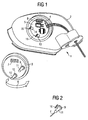
- FIG. 1 shows an exterior rear-view mirror 1 with a carrier plate 2 and an adjustment drive 3.
- the components of the exterior rear-view mirror 1, which are irrelevant for the understanding of the invention, are not shown in FIG. 1 .
- a drying room 4 is provided, which by the Cover-like attachment of the adjustment drive 3 on the open side of the Drying room 4 can be sealed watertight.
- a circuit board 5 is provided in the drying room 4 on which various electronic Components are equipped.
- Fig. 1 only the back of the actuator 3 can be seen.
- the adjustment drive 3 is turned according to the movement arrow 6, so that the connector strip 7 can be brought into engagement with the functionally complementary connector strip 8, and then fastened.
- two servomotors are arranged which, as is known from the prior art, via two toothed racks 9 and 10, of which only the end facing away from the glass module can be seen in FIG. 1 , can drive a glass assembly, not shown, in two levels.
- a rod-shaped, permanent magnetic magnetic element 11 and 12 attached at the end of the racks 9 and 10 facing away from the glass assembly.
- the magnetic elements 11 and 12 thus take on the adjusting movements of the racks 9 and 10 during the adjustment part of the glass assembly, not shown.
- the circuit board 5 and the underlying support plate 2 are two recesses 13 and 14 (Circuit board 5) or two recesses, not shown (carrier plate 2) provided so that the magnetic elements 11 and 12 during the adjustment the glass assembly without resistance and through the edge of the recesses 13 and 14 can dive into the carrier plate 2.
- On the edge the recesses 13 and 14 are magnetic sensors 15 and 16, respectively provided, which is connected to an evaluation unit 17 via the printed circuit board 5 are contacted.
- the arrangement of the magnetic elements 11 and 12 and the Magnetic sensors 15 and 16 allow the position of the glass assembly with respect to the two intended pivot axes by operating the Determine magnetic sensors in the bipolar slide-by mode.
- Fig. 2 shows the relative arrangement of the magnetic element 11 to the magnetic sensor 16 designed in the manner of a Hall sensor after assembly of the adjusting drive 3. It can be seen that the magnetic element 11 parallel to the magnetic sensor 16 during the linear actuating movement of the rack 9 in the Z direction at a constant distance is proceeded to this.
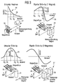
- FIG. 3 shows four operating modes of a combination of a magnetic element with a magnetic sensor, the relative position between the magnetic element and magnetic sensor being given as the input variable and an output voltage of the magnetic sensor being given as the output signal.
- the drawing on the far left shows the unipolar head-on operating mode, in which the magnetic element 17 is approached frontally to the magnetic sensor 18.
- Diagram 19 shows the course of the output signal 20 over the distance between the magnetic sensor 18 and the magnetic element 17 shown on the Z-axis. It can be seen that the output signal 20 approaches the zero value asymptotically as the distance between the magnetic element 17 and the magnetic sensor 18 increases, so that adjusting movements can only be insufficiently resolved in this area.
- the third image from the left in FIG. 3 shows the combination of a magnetic element 21 with a magnetic sensor 22 in the unipolar slide-by mode.
- the magnetic element 21 In this operating mode, the magnetic element 21 is guided past the magnetic sensor in parallel at a constant distance y.
- the output signal 23 of the magnetic sensor rises in a curve and reaches a maximum as soon as the magnetic element 21 faces the magnetic sensor 22 with a minimal distance. Starting from the maximum of the output signal, the output signal drops again when the magnetic element 21 is shifted further.
- the curve of the output signal 23 has only a very slight slope in the area of the maximum, which is why movements by the combination of the magnetic element 21 with the magnetic sensor 22 in the unipolar slide-by mode of operation in the area of the output signal maximum can only be poorly resolved.
- the second image from the left in FIG. 3 shows the combination of a magnetic element 24 with a magnetic sensor 25 in a bipolar slide-by mode.
- the magnetic element 24 has two sections, the magnetic polarity of which is opposite.
- both a south and a north pole of the magnetic element 24 lie opposite the magnetic sensor 25.
- the magnetic element 24 is guided past the magnetic sensor 25 at a constant distance y parallel to the magnetic sensor 25. This results in an output signal curve 26.
- the output signal 26 has a linear slope around the zero point that is reached when the magnetic element 24 is directly opposite the magnetic sensor 25. From a certain distance of the magnetic element 24 to the magnetic sensor 25, the slope of the output curve 26 drops and reaches an absolute maximum or an absolute minimum.
- the biploar slide-by mode is particularly well suited, since movements that lead to changes in distance between the magnetic element 24 and the magnetic sensor 25 occur in the area between the absolute minimum and the absolute maximum can be resolved evenly due to the uniform slope.
- the magnetic sensor it should be noted that it is advantageous if, with maximum deflection of the glass assembly in one or the opposite direction, there is still a sufficient distance between the output signal of the magnetic sensor and the absolute maximum or absolute minimum.
- the fourth image from the left in FIG. 3 shows the combination of a magnetic element 27 with a magnetic sensor 28 in the bipolar slide-by mode, the magnetic element 27 having two separate magnets 29 and 30, which are at a certain distance from one another and have opposite polarity are.
- the output signal 31 of the magnetic sensor 28 in this operating mode corresponds qualitatively to the output signal curve of the output signal 26. It can be seen that the gradient of the output signal curve can be varied by varying the distance between the magnetic partial elements 29 and 30.
- FIG. 4 shows the magnetic flux density in [mT] of a magnetic element as a function of the magnetic position relative to a reference point when the magnetic element is moved in the direction of movement z in [mm].
- Four curves of the magnetic flux density for different distances y in [mm] are plotted in FIG. 4 . It can be seen that the magnetic flux density changes almost linearly with the value of z when the magnetic element moves in the region of the zero point. The diagram also shows that the magnetic flux density in the area around the zero point changes only slightly with the variation of the distance y.
Landscapes
- Engineering & Computer Science (AREA)
- Multimedia (AREA)
- Mechanical Engineering (AREA)
- Measurement Of Length, Angles, Or The Like Using Electric Or Magnetic Means (AREA)
- Transmission And Conversion Of Sensor Element Output (AREA)
- Rear-View Mirror Devices That Are Mounted On The Exterior Of The Vehicle (AREA)
Abstract
Description
- Fig. 1
- Teile eines Außenrückspiegels in perspektivischer Ansicht;
- Fig. 2
- das Zusammenwirken eines Magnetsensors und eines Magnetelements in einem Außenrückspiegel gemäß Fig. 1 in perspektivischer Ansicht;
- Fig. 3
- vier Betriebsarten von Magnetsensorsystemen;
- Fig. 4
- die magnetische Flußdichte eines Magnetelements in Abhängigkeit der Magnetposition relativ zu einem Referenzpunkt.
Claims (24)
- Außenrückspiegel für ein Kraftfahrzeug mit einer verstellbar gelagerten Glasbaugruppe und einem elektrischen Verstellantrieb zur fernsteuerbaren Verstellung der Glasbaugruppe, wobei die Position der Glasbaugruppe, insbesondere die Winkelstellung, mit zumindest einem Sensor bestimmbar ist,
dadurch gekennzeichnet,
daß der Sensor in der Art eines Magnetsensors (15, 16) ausgebildet ist, der mit einem im Außenrückspiegel (1) vorgesehenen Magnetelement (11, 12) in der Art zusammenwirkt, daß der Magnetsensor (15, 16) oder das Magnetelement (11, 12) an der Verstellbewegung der Glasbaugruppe teilnimmt und der Magnetsensor (15, 16) in Abhängigkeit von der Position des Magnetelements (11, 12) ein veränderliches Ausgangssignal liefert, aus dem in einer Auswerteeinheit die Position der Glasbaugruppe ableitbar ist. - Außenrückspiegel nach Anspruch 1,
dadurch gekennzeichnet,
daß der Magnetsensor (15, 16) in der Art eines Hallsensors ausgebildet ist. - Außenrückspiegel nach Anspruch 1 oder 2,
dadurch gekennzeichnet,
daß der Magnetsensor eine Schaltung zur Signalverstärkung und/oder Temperaturkompensation aufweist. - Außenrückspiegel nach einem der Ansprüche 1 bis 3,
dadurch gekennzeichnet,
daß der Magnetsensor mit einer Versorgungsspannung von circa 5V DC versorgt wird. - Außenrückspiegel nach einem der Ansprüche 1 bis 4,
dadurch gekennzeichnet,
daß der Magnetsensor in Abhängigkeit von der Position des Magnetelements eine Ausgangsspannung im Spannungsbereich von 5% bis 95% der Versorgungsspannung abgibt. - Außenrückspiegel nach einem der Ansprüche 1 bis 5,
dadurch gekennzeichnet,
daß das Magnetelement (11, 12) in der Art eines Dauermagneten ausgebildet ist. - Außenrückspiegel nach einem der Ansprüche 1 bis 6,
dadurch gekennzeichnet,
daß das Magnetelement (11, 12) eine insgesamt stabförmige Geometrie aufweist. - Außenrückspiegel nach einem der Ansprüche 1 bis 7,
dadurch gekennzeichnet,
daß das Magnetelement (27) aus mehreren Magnetteilelementen (29, 30) zusammengesetzt ist. - Außenrückspiegel nach einem der Ansprüche 1 bis 8,
dadurch gekennzeichnet,
daß der Magnetsensor (25, 28) und das Magnetelement (24, 27) in der Art ausgebildet und angeordnet sind, daß die Position des Magnetelements (24, 27) relativ zum Magnetsensor (25, 28) in der Betriebsart "Bipolar Slide-by" bestimmbar ist. - Außenrückspiegel nach einem der Ansprüche 1 bis 9,
dadurch gekennzeichnet,
daß der Magnetsensor (15, 16) feststehend auf einem Grundkörper (2) des Außenrückspiegels (1) angeordnet ist und das Magnetelement (11, 12) an der Verstellbewegung der Glasbaugruppe teilnimmt. - Außenrückspiegel nach Anspruch 10,
dadurch gekennzeichnet,
daß der Grundkörper (2) im Bereich des Magnetsensors (15, 16) Vertiefungen oder Ausnehmungen (13, 14) aufweist, in die das Magnetelement (11, 12) in Abhängigkeit von der Position der Glasbaugruppe mit unterschiedlicher Tiefe eindringen kann. - Außenrückspiegel nach einem der Ansprüche 1 bis 11,
dadurch gekennzeichnet,
daß das Magnetelement (11, 12) in der Art angeordnet ist, daß es bei der Verstellbewegung der Glasbaugruppe mit im wesentlichen konstanten Abstand parallel zum Magnetsensor (15, 16) verfahren wird. - Außenrückspiegel nach einem der Ansprüche 1 bis 12,
dadurch gekennzeichnet,
daß das Magnetelement (11, 12) in den Verstellantrieb (3) integriert ist. - Außenrückspiegel nach Anspruch 13,
dadurch gekennzeichnet,
daß der Verstellantrieb (3) ein Getriebeelement, insbesondere eine Zahnstange (9, 10) oder einen Schneckenstößel, aufweist, durch das eine Stellbewegung auf die Glasbaugruppe übertragbar ist, wobei das Magnetelement (11, 12) an der Stellbewegung des Getriebeelements teilnimmt. - Außenrückspiegel nach Anspruch 14,
dadurch gekennzeichnet,
daß das Magnetelement (11, 12) am Ende des Getriebeelements, insbesondere am Ende einer Zahnstange (9, 10) oder am Ende eines Schneckenstößels, befestigt ist. - Außenrückspiegel nach Anspruch 14,
dadurch gekennzeichnet,
daß zur Herstellung des Getriebeelements ein Magnetelement mit Kunststoff umspritzt wird. - Außenrückspiegel nach Anspruch 14,
dadurch gekennzeichnet,
daß das Getriebeelement unter Verwendung eines magnetisierbaren Werkstoffs urgeformt wird. - Außenrückspiegel nach Anspruch 17,
dadurch gekennzeichnet,
daß das Getriebeelement unter Verwendung eines Kunststoffs, der ein kunststoffgebundenes Magnetmaterial enthält, durch Spritzgießen hergestellt ist. - Außenrückspiegel nach Anspruch 18,
dadurch gekennzeichnet,
daß das Getriebeelement in einen Mehrkomponentenspritzgießverfahren hergestellt ist, bei dem ein Kunststoff, der ein kunststoffgebundenes Magnetmaterial enthält, mit einem anderen Kunststoff umspritzt wird. - Außenrückspiegel nach einem der Ansprüche 1 bis 19,
dadurch gekennzeichnet,
daß der Magnetsensor mittels zumindest einer Leiterbahnen kontaktierbar ist, die mit Kunststoff umspritzt ist. - Außenrückspiegel nach einem der Ansprüche 1 bis 20,
dadurch gekennzeichnet,
daß der Magnetsensor mit Kunststoff umspritzt ist. - Außenrückspiegel nach einem der Ansprüche 1 bis 21,
dadurch gekennzeichnet,
daß der Magnetsensor in eine Dichtmasse, insbesondere Silikon, eingegossen ist. - Außenrückspiegel nach einem der Ansprüche 1 bis 22,
dadurch gekennzeichnet,
daß der Magnetsensor (15, 16) in einem abdichtbaren Trockenraum (4) des Außenrückspiegels angeordnet ist. - Außenrückspiegel nach einem der Ansprüche 1 bis 23,
dadurch gekennzeichnet,
daß der Außenrückspiegel (1) zwei Magnetsensoren (15, 16) und zwei funktionskomplementär angeordnete Magnetelemente (11, 12) aufweist, so daß die Winkelposition der Glasbaugruppe gegenüber einer X-Achse und einer dazu nicht parallel verlaufenden Y-Achse bestimmbar ist.
Applications Claiming Priority (2)
| Application Number | Priority Date | Filing Date | Title |
|---|---|---|---|
| DE19952812 | 1999-11-02 | ||
| DE19952812A DE19952812C1 (de) | 1999-11-02 | 1999-11-02 | Außenrückspiegel mit Positionssensor |
Publications (2)
| Publication Number | Publication Date |
|---|---|
| EP1097845A2 true EP1097845A2 (de) | 2001-05-09 |
| EP1097845A3 EP1097845A3 (de) | 2003-06-04 |
Family
ID=7927723
Family Applications (1)
| Application Number | Title | Priority Date | Filing Date |
|---|---|---|---|
| EP00123822A Withdrawn EP1097845A3 (de) | 1999-11-02 | 2000-11-02 | Aussenrückspiegel mit Positionssensor |
Country Status (3)
| Country | Link |
|---|---|
| US (1) | US6382806B1 (de) |
| EP (1) | EP1097845A3 (de) |
| DE (1) | DE19952812C1 (de) |
Cited By (2)
| Publication number | Priority date | Publication date | Assignee | Title |
|---|---|---|---|---|
| EP1749697A1 (de) * | 2005-08-01 | 2007-02-07 | Murakami Corporation | Steuervorrichtung für elektrische Kraftfahrzeugspiegelanordnung |
| DE102010030481A1 (de) | 2010-06-24 | 2011-12-29 | Zf Friedrichshafen Ag | Verfahren zum Abschätzen der Fahrergröße |
Families Citing this family (7)
| Publication number | Priority date | Publication date | Assignee | Title |
|---|---|---|---|---|
| DE10210894A1 (de) * | 2002-03-07 | 2003-09-18 | Valeo Schalter & Sensoren Gmbh | Rückspiegel für Fahrzeuge |
| JP4012460B2 (ja) * | 2002-11-28 | 2007-11-21 | 株式会社東海理化電機製作所 | 車両用アウタミラー装置 |
| JP2006044511A (ja) * | 2004-08-05 | 2006-02-16 | Murakami Corp | ミラー及び角度検出装置 |
| JP4303657B2 (ja) * | 2004-08-05 | 2009-07-29 | 株式会社村上開明堂 | ミラー及び角度検出装置 |
| JP2006096130A (ja) * | 2004-09-29 | 2006-04-13 | Murakami Corp | ミラー及び角度検出装置 |
| JP4831813B2 (ja) * | 2006-01-30 | 2011-12-07 | 株式会社村上開明堂 | 位置検出装置および自動車用ミラーの鏡面角度検出装置 |
| US20240190351A1 (en) * | 2022-12-09 | 2024-06-13 | Magna Mirrors Of America, Inc. | Vehicular driver monitoring system |
Citations (2)
| Publication number | Priority date | Publication date | Assignee | Title |
|---|---|---|---|---|
| DE19841551A1 (de) | 1998-09-11 | 2000-04-06 | Hohe Gmbh & Co Kg | Elektrischer Außenrückspiegel |
| DE19928384A1 (de) | 1999-06-21 | 2001-01-11 | Hohe Gmbh & Co Kg | Außenrückspiegel mit Trockenkammer |
Family Cites Families (9)
| Publication number | Priority date | Publication date | Assignee | Title |
|---|---|---|---|---|
| DE1303818C2 (de) * | 1966-09-22 | 1973-08-02 | Siemens Ag | Analoger hysteresefreier weggeber mit hallgenerator |
| GB2071333B (en) * | 1980-02-22 | 1984-02-01 | Sony Corp | Magnetic sensor device |
| US4726640A (en) * | 1985-09-24 | 1988-02-23 | Ricoh Company, Ltd. | Optical deflector with a pneumatic and a magnetic bearing |
| JPH03500630A (ja) * | 1987-08-03 | 1991-02-14 | イエンセン カイ ベルグ | 舵取歯車の位置に応答して車両のバツクミラーを調節する制御装置 |
| US4770522A (en) * | 1987-11-02 | 1988-09-13 | Siegel-Robert, Inc. | Automobile mirror position sensor and adjuster assembly |
| JPH0629002B2 (ja) * | 1988-07-13 | 1994-04-20 | 株式会社東海理化電機製作所 | 自動車用電動ミラー装置 |
| US5177631A (en) * | 1991-06-28 | 1993-01-05 | Eastman Kodak Company | Magnetic position sensor |
| JP3396018B2 (ja) * | 1997-03-25 | 2003-04-14 | 株式会社村上開明堂 | ミラー位置検出装置 |
| JP3343206B2 (ja) * | 1997-08-07 | 2002-11-11 | 株式会社東海理化電機製作所 | 自動車用ミラーアセンブリ |
-
1999
- 1999-11-02 DE DE19952812A patent/DE19952812C1/de not_active Expired - Lifetime
-
2000
- 2000-10-27 US US09/699,084 patent/US6382806B1/en not_active Expired - Lifetime
- 2000-11-02 EP EP00123822A patent/EP1097845A3/de not_active Withdrawn
Patent Citations (2)
| Publication number | Priority date | Publication date | Assignee | Title |
|---|---|---|---|---|
| DE19841551A1 (de) | 1998-09-11 | 2000-04-06 | Hohe Gmbh & Co Kg | Elektrischer Außenrückspiegel |
| DE19928384A1 (de) | 1999-06-21 | 2001-01-11 | Hohe Gmbh & Co Kg | Außenrückspiegel mit Trockenkammer |
Cited By (3)
| Publication number | Priority date | Publication date | Assignee | Title |
|---|---|---|---|---|
| EP1749697A1 (de) * | 2005-08-01 | 2007-02-07 | Murakami Corporation | Steuervorrichtung für elektrische Kraftfahrzeugspiegelanordnung |
| US7722200B2 (en) | 2005-08-01 | 2010-05-25 | Murakami Corporation | Electric mirror control device |
| DE102010030481A1 (de) | 2010-06-24 | 2011-12-29 | Zf Friedrichshafen Ag | Verfahren zum Abschätzen der Fahrergröße |
Also Published As
| Publication number | Publication date |
|---|---|
| US6382806B1 (en) | 2002-05-07 |
| EP1097845A3 (de) | 2003-06-04 |
| DE19952812C1 (de) | 2001-08-16 |
Similar Documents
| Publication | Publication Date | Title |
|---|---|---|
| DE69511063T2 (de) | Inkrementaler geschwindigkeits- und / oder lagegeber | |
| EP1250534B1 (de) | Antrieb eines stellventils mit sensiereinheit zur ventilpositionserfassung | |
| EP1664801B1 (de) | Magnetfeldsensor | |
| WO2000054010A1 (de) | Längenmesssystem mit mindestens einem magnetischen massstab | |
| DE4320939A1 (de) | Dichtung | |
| EP1128159A2 (de) | Mechanische Welle mit integrierter Magnetanordnung | |
| EP0984121A2 (de) | Antriebseinrichtung mit einem Stellantrieb | |
| DE19952812C1 (de) | Außenrückspiegel mit Positionssensor | |
| DE4405438A1 (de) | Drehzahlgeber | |
| DE19738316A1 (de) | Berührungsloser Wegmesser insbesondere zur Verschleißmessung von Bremsklötzen | |
| DE19848081A1 (de) | Antriebseinrichtung mit einem Stellantrieb | |
| DE10039588B4 (de) | Gebereinrichtung | |
| DE2735673C2 (de) | Potentiometer ohne Schleifkontakt | |
| EP0800087B1 (de) | Drehzahlsensor | |
| DE3730900C2 (de) | Antrieb für Wischeranlagen an Kraftfahrzeugen | |
| DE19612422A1 (de) | Potentiometereinrichtung mit einem linear verschiebbaren Stellelement und signalerzeugenden Mitteln | |
| DE4303403A1 (en) | Linear displacement position detector - has encapsulated magnetoresistive sensor element in electromagnetically screened chamber with bar magnet activation | |
| WO1998057127A1 (de) | Wegsensor | |
| DE10244703A1 (de) | Einrichtung zur Messung von Wegen und/oder Positionen | |
| DE102021101332A1 (de) | Sensoranordnung für ein Lenksystem eines Fahrzeugs; Lenksystem; Fahrzeug; Verwendung einer Sensoranordnung, Verfahren zur Herstellung eines Lenksystems | |
| DE4210934C1 (de) | ||
| EP1269121B1 (de) | Messvorrichtung zur berührungslosen erfassung eines drehwinkels | |
| EP1514990A2 (de) | Verstelleinrichtung für ein Kraftfahrzeug | |
| DE29614974U1 (de) | Steuervorrichtung zur Kompensation von Offset-Anteilen eines periodischen Signals | |
| DE112010003114T5 (de) | Gleichstrom-Elektromotor, insbesondere für Bewegungen an Kraftfahrzeugen wieFensterheber, Sitzversteller, Scheibenwischer und dergleichen |
Legal Events
| Date | Code | Title | Description |
|---|---|---|---|
| PUAI | Public reference made under article 153(3) epc to a published international application that has entered the european phase |
Free format text: ORIGINAL CODE: 0009012 |
|
| AK | Designated contracting states |
Kind code of ref document: A2 Designated state(s): AT BE CH CY DE DK ES FI FR GB GR IE IT LI LU MC NL PT SE TR |
|
| AX | Request for extension of the european patent |
Free format text: AL;LT;LV;MK;RO;SI |
|
| RIC1 | Information provided on ipc code assigned before grant |
Ipc: 7B 60R 7/06 B Ipc: 7B 60R 1/072 A |
|
| PUAL | Search report despatched |
Free format text: ORIGINAL CODE: 0009013 |
|
| AK | Designated contracting states |
Designated state(s): AT BE CH CY DE DK ES FI FR GB GR IE IT LI LU MC NL PT SE TR |
|
| AX | Request for extension of the european patent |
Extension state: AL LT LV MK RO SI |
|
| AKX | Designation fees paid | ||
| REG | Reference to a national code |
Ref country code: DE Ref legal event code: 8566 |
|
| STAA | Information on the status of an ep patent application or granted ep patent |
Free format text: STATUS: THE APPLICATION IS DEEMED TO BE WITHDRAWN |
|
| 18D | Application deemed to be withdrawn |
Effective date: 20031205 |