EP1514990A2 - Verstelleinrichtung für ein Kraftfahrzeug - Google Patents
Verstelleinrichtung für ein Kraftfahrzeug Download PDFInfo
- Publication number
- EP1514990A2 EP1514990A2 EP04020231A EP04020231A EP1514990A2 EP 1514990 A2 EP1514990 A2 EP 1514990A2 EP 04020231 A EP04020231 A EP 04020231A EP 04020231 A EP04020231 A EP 04020231A EP 1514990 A2 EP1514990 A2 EP 1514990A2
- Authority
- EP
- European Patent Office
- Prior art keywords
- adjusting device
- sensor part
- passive
- active
- passive sensor
- Prior art date
- Legal status (The legal status is an assumption and is not a legal conclusion. Google has not performed a legal analysis and makes no representation as to the accuracy of the status listed.)
- Withdrawn
Links
Images


Classifications
-
- E—FIXED CONSTRUCTIONS
- E05—LOCKS; KEYS; WINDOW OR DOOR FITTINGS; SAFES
- E05F—DEVICES FOR MOVING WINGS INTO OPEN OR CLOSED POSITION; CHECKS FOR WINGS; WING FITTINGS NOT OTHERWISE PROVIDED FOR, CONCERNED WITH THE FUNCTIONING OF THE WING
- E05F15/00—Power-operated mechanisms for wings
- E05F15/40—Safety devices, e.g. detection of obstructions or end positions
-
- E—FIXED CONSTRUCTIONS
- E05—LOCKS; KEYS; WINDOW OR DOOR FITTINGS; SAFES
- E05F—DEVICES FOR MOVING WINGS INTO OPEN OR CLOSED POSITION; CHECKS FOR WINGS; WING FITTINGS NOT OTHERWISE PROVIDED FOR, CONCERNED WITH THE FUNCTIONING OF THE WING
- E05F15/00—Power-operated mechanisms for wings
- E05F15/60—Power-operated mechanisms for wings using electrical actuators
- E05F15/603—Power-operated mechanisms for wings using electrical actuators using rotary electromotors
- E05F15/665—Power-operated mechanisms for wings using electrical actuators using rotary electromotors for vertically-sliding wings
- E05F15/689—Power-operated mechanisms for wings using electrical actuators using rotary electromotors for vertically-sliding wings specially adapted for vehicle windows
- E05F15/695—Control circuits therefor
-
- E—FIXED CONSTRUCTIONS
- E05—LOCKS; KEYS; WINDOW OR DOOR FITTINGS; SAFES
- E05F—DEVICES FOR MOVING WINGS INTO OPEN OR CLOSED POSITION; CHECKS FOR WINGS; WING FITTINGS NOT OTHERWISE PROVIDED FOR, CONCERNED WITH THE FUNCTIONING OF THE WING
- E05F11/00—Man-operated mechanisms for operating wings, including those which also operate the fastening
- E05F11/38—Man-operated mechanisms for operating wings, including those which also operate the fastening for sliding windows, e.g. vehicle windows, to be opened or closed by vertical movement
- E05F11/382—Man-operated mechanisms for operating wings, including those which also operate the fastening for sliding windows, e.g. vehicle windows, to be opened or closed by vertical movement for vehicle windows
-
- E—FIXED CONSTRUCTIONS
- E05—LOCKS; KEYS; WINDOW OR DOOR FITTINGS; SAFES
- E05Y—INDEXING SCHEME ASSOCIATED WITH SUBCLASSES E05D AND E05F, RELATING TO CONSTRUCTION ELEMENTS, ELECTRIC CONTROL, POWER SUPPLY, POWER SIGNAL OR TRANSMISSION, USER INTERFACES, MOUNTING OR COUPLING, DETAILS, ACCESSORIES, AUXILIARY OPERATIONS NOT OTHERWISE PROVIDED FOR, APPLICATION THEREOF
- E05Y2201/00—Constructional elements; Accessories therefor
- E05Y2201/60—Suspension or transmission members; Accessories therefor
- E05Y2201/622—Suspension or transmission members elements
- E05Y2201/64—Carriers
-
- E—FIXED CONSTRUCTIONS
- E05—LOCKS; KEYS; WINDOW OR DOOR FITTINGS; SAFES
- E05Y—INDEXING SCHEME ASSOCIATED WITH SUBCLASSES E05D AND E05F, RELATING TO CONSTRUCTION ELEMENTS, ELECTRIC CONTROL, POWER SUPPLY, POWER SIGNAL OR TRANSMISSION, USER INTERFACES, MOUNTING OR COUPLING, DETAILS, ACCESSORIES, AUXILIARY OPERATIONS NOT OTHERWISE PROVIDED FOR, APPLICATION THEREOF
- E05Y2400/00—Electronic control; Electrical power; Power supply; Power or signal transmission; User interfaces
- E05Y2400/10—Electronic control
- E05Y2400/32—Position control, detection or monitoring
- E05Y2400/322—Position control, detection or monitoring by using absolute position sensors
- E05Y2400/328—Position control, detection or monitoring by using absolute position sensors of the linear type
-
- E—FIXED CONSTRUCTIONS
- E05—LOCKS; KEYS; WINDOW OR DOOR FITTINGS; SAFES
- E05Y—INDEXING SCHEME ASSOCIATED WITH SUBCLASSES E05D AND E05F, RELATING TO CONSTRUCTION ELEMENTS, ELECTRIC CONTROL, POWER SUPPLY, POWER SIGNAL OR TRANSMISSION, USER INTERFACES, MOUNTING OR COUPLING, DETAILS, ACCESSORIES, AUXILIARY OPERATIONS NOT OTHERWISE PROVIDED FOR, APPLICATION THEREOF
- E05Y2400/00—Electronic control; Electrical power; Power supply; Power or signal transmission; User interfaces
- E05Y2400/10—Electronic control
- E05Y2400/32—Position control, detection or monitoring
- E05Y2400/334—Position control, detection or monitoring by using pulse generators
- E05Y2400/338—Position control, detection or monitoring by using pulse generators of the linear type
-
- E—FIXED CONSTRUCTIONS
- E05—LOCKS; KEYS; WINDOW OR DOOR FITTINGS; SAFES
- E05Y—INDEXING SCHEME ASSOCIATED WITH SUBCLASSES E05D AND E05F, RELATING TO CONSTRUCTION ELEMENTS, ELECTRIC CONTROL, POWER SUPPLY, POWER SIGNAL OR TRANSMISSION, USER INTERFACES, MOUNTING OR COUPLING, DETAILS, ACCESSORIES, AUXILIARY OPERATIONS NOT OTHERWISE PROVIDED FOR, APPLICATION THEREOF
- E05Y2900/00—Application of doors, windows, wings or fittings thereof
- E05Y2900/50—Application of doors, windows, wings or fittings thereof for vehicles
- E05Y2900/53—Type of wing
- E05Y2900/55—Windows
Definitions
- the invention relates to an adjusting device for a motor vehicle for Adjusting a movable element of the adjusting device; the adjustment has a sensor system with at least one active sensor part and at least a passive sensor part.
- the sensor system is used for measuring or for Determining the position or location of the movable element.
- the active Sensor part is hereinafter understood that part of the sensor system, the one generates analog or digital sensor signal, the position or the location of the indicates immediately movable element or from or with the position or the location of the movable element is indirectly determinable.
- Under the passive Sensor part is that part of the sensor system understood that a physical quantity - for example, the magnetic field, the electric field or the like in the region of the active sensor part - changed in such a way that this from the active sensor part detected and can be detected to form the sensor signal.
- Such adjustment is for example from the international Patent application WO 00/54010 known.
- the passive sensor part formed by a magnetic rod, in which the angle of the magnetic field in the longitudinal direction of the rod rotates. By measuring the Direction of the magnetic field with the help of the active sensor part can thus on the close absolute location of the movable element.
- the invention has for its object to provide an adjustment, which is as easy and inexpensive to produce.
- the invention provides that the active sensor part arranged stationary and is formed by a capacitive sensor.
- the passive sensor part forms a Part of the movable element.
- the adjusting device is designed such that as active Sensor part, a capacitive sensor is used.
- Capacitive sensors can be for example, form in the simplest form by only two capacitor plates, so that the active sensor part in the adjusting device according to the invention very is inexpensive to produce.
- the passive sensor part is an integral part of the movable Elements, so that the passive sensor part in the production of the movable element "at the same time" can be produced.
- the passive sensor part is on the movable element integrally formed.
- the passive sensor part preferably has a comb-shaped Profile on the electric field very much when passing by the active sensor part changed abruptly. From the active sensor part are then approximately rectangular Output signals, so thus quasi-digital signals delivered.
- the passive one indicates Sensor part preferably as a capacity-changing profile on a sinusoidal profile.
- the capacitance-changing profile of the passive sensor part can be monotonous have rising or monotonically sloping course.
- measuring the electric field strength in the region of the active sensor part or by measuring the Capacity of the active part of the sensor can thus be adjusted to the absolute location of the movable Elements are closed.
- a rising or falling profile can over it but also for initialization or normalization of the position measuring system or used for synchronization with another relative position measuring system become. In this way, for example, measuring tolerances can be eliminated or at least reduce.
- An absolute location measurement using the sensor system is also possible, if the passive sensor part has at least two sensor tracks. By a appropriate coding of the two sensor tracks relative to each other can then on the absolute position of the movable element to be closed.
- the profile of the passive sensor part can be particularly cost-effective and simple corresponding configuration of a plastic material may be formed.
- the Carrier part is preferably made of metal, for example, a flat sheet.
- the carrier part itself may have a capacity-changing profile, so the carrier part forms its own "sensor track”.
- the clip element can be off Plastic be formed.
- the clip element is integral with a Housing of the active sensor part connected to the production costs as low as possible to keep.
- the housing of the active Sensor part has at least one stop surface for the movable element, to the the movable element strikes in its upper and / or lower end position. at an integration of the stop surface in the housing of the sensor part can thus be dispensed with an additional separate stop.
- the sensor system has an evaluation device, in particular a Electronic circuit that evaluates the sensor signal of the active sensor part.
- the Evaluation device is preferably designed such that it from the sensor signal of the active sensor part forms an analog or digital measuring signal, which is the absolute or relative position of the movable element.
- the evaluation device can be fixed, for example, stationary.
- the evaluation device in the housing of the active sensor part is advantageous accommodated, thus saving a separate housing for the evaluation becomes.
- the evaluation device is connected to at least one cable a drive of the adjusting device connected control device of Adjusting device in connection; while the control device is configured in such a way that it evaluates the analog or digital measurement signal of the evaluation and the control of the drive taking into account the absolute or relative Position of the movable element makes.
- a radio link between the controller and the Evaluation are used instead of a cable.
- the evaluation device is housed in the wet area of the motor vehicle, it is considered advantageous if the at least one cable and the housing the evaluation device are connected watertight to damage due to moisture avoid. The same applies if the evaluation device in the housing of the active sensor part is housed.
- the watertight connection between the cable and the housing of the Evaluation device or the housing of the active sensor part can be inexpensive and thus advantageously be effected by the fact that the housing facing the end of the cable and the housing are molded together with plastic. expensive Wet room plug can be saved.
- the passive sensor part can, for example, on a cable drum of a drive system be arranged the adjusting device, regardless of whether it is in the Adjustment device to a window regulator, a seat adjustment, a sunroof or another vehicle component is.
- the passive sensor part can instead also be arranged on a pulley over which a flexible traction means, For example, a drive cable is guided.
- the adjusting device may in particular be a cable window lifter act.
- the passive sensor part of the sensor system is then preferably at one Driver for the window of the window lifter attached.
- the active sensor part is preferably attached to a guide rail of the window regulator.
- To attach the driver to the associated guide rail of the Window lift has this preferably in cross-section L-shaped guide slots, through which the associated guide rail is passed.
- the window glass Attachment area of the driver in particular, for example, a jaw of the mounting area - made of metal and is by plastic injection with one of the guide rail of the window lift guided sliding area (made of plastic) of the Tied to driver, wherein at the sliding portion of the passive sensor part in one piece is formed.
- the passive sensor part is also made of plastic and is in Frame of Kunststoffumspritzens been formed in forming the sliding portion.
- the catch is preferably with two clamping jaws equipped, of which at least one by a plastic-coated metal part is formed.
- the active sensor part is preferably on the guide rail of the window lifter with clipped on a clip element.
- the clip element is preferably integral to the Housing of the active sensor part formed.
- the passive sensor part may also be in a design or decorative element, In particular, a cover for the drive of the adjusting integrated be. This is especially recommended when it comes to the Adjustment is a Wegverstell Road because then, for example, the Seat rail assembly of the vehicle seat by the passive sensor part at least partially covered.
- the object of the invention is moreover - this is a second Embodiment of the invention - by an adjusting device with a sensor system solved, in which the adjusting device is a window, at the driver for the Window as a passive sensor part a magnetic field changing element arranged is.
- the passive sensor part is an integral part, in particular an integrally formed part of the movable element forms.
- the magnetic field-changing "profile" of the passive sensor part can be such be configured so that the active sensor part digital, sinusoidal or monotone Ascending or monotonically decreasing electrical signals generated.
- the profile can be passively alter the magnetic return flow of an existing magnetic field or instead or in addition generate your own magnetic field.
- that can passive sensor part for generating a separate magnetic field periodically arranged, equidistant magnetic poles with alternating magnetic field orientation (eg North Pole South Pole North Pole South Pole etc.).
- the magnetic field-modifying element can have two sensor tracks have, so that an absolute location measurement using the sensor system allows becomes.
- the active sensor part is a magnetoresistive Sensor, in particular a Hall sensor.
- the Hall sensor is biased.
- the magnetic field-changing element for example, designed such that the Magnetic properties vary over the length of the active sensor part such that the radially directed magnetic field lines in the longitudinal direction of the passive sensor part are continuously or segmented angularly aligned.
- the passive sensor part is preferably formed by an injection molded part, in which Magnetic material is injected.
- the magnetic material is, for example, after Injection molding magnetically aligned by an external, strong magnetic field.
- the magnetic material can be in the passive sensor part as separate parts from the outside be used.
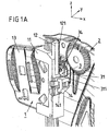
- a window lift as adjusting.
- the driver 1 comprises a slider or sliding region 11 made of plastic, a passive Sensor part 12, a mounting portion 13 for fixing a window pane in Shape of at least one jaw 13 and a nipple chamber 14th
- an active sensor part 3 is attached to a housing 31.
- the attachment of the housing 31 to the guide rail 2 is based on a Clip element 32 of the active sensor part 3, which is clipped to the guide rail 2.
- an electronic circuit is arranged, which generates an electrical measurement signal, the position of the driver 1 relative to Indicates guide rail 2.
- the passive sensor part 12 operates as a so-called "scale” and has for this purpose comb-like structure on.
- the scale 12 is at two U-shaped sensor elements 34th the active sensor part 3 passes, so that the sensor elements 34 the comb-like structure of the scale 12 can capture.
- An essential advantage of this embodiment is that in this Arrangement no electrical connection lines led to the moving element Need to become; because the active part of the sensor, as a rule - from radio transmission or the like aside - requires an electrical connection is arranged body-mounted and thus easily electrically connected or "wired".
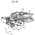
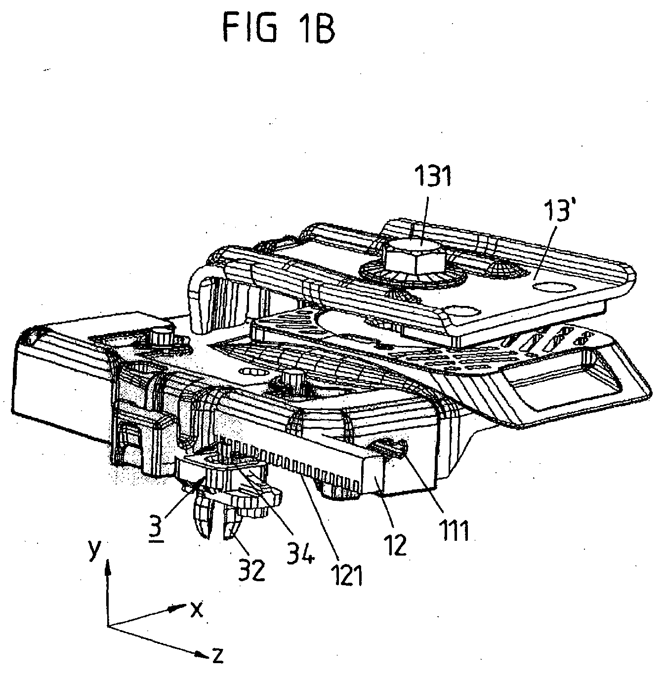
- FIG. 1b shows another view of the window lifter shown in FIG. 1a shown.
- the guide rail 2 is omitted to a to allow better view of the active sensor element 3.
- a clip element 32 of the passive sensor part 12 visible. With this clip element 32 is the housing 31 of the passive sensor element 12 on the guide rail. 2 clipped.
- FIG. 1 b shows a second clamping jaw 13 'whose distance from the Jaw 13 by means of a screw 131 is adjustable.
- Figure 1 b can be seen beyond guide slots 111 with an L-shaped Cross-section.
- the guide slots 111 serve to secure the driver 1 to the in the figure 1 b, not shown guide rail. 2
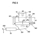
- FIG. 2 shows the active sensor element 3 in detail. Good to see in particular the clip element 32, with which the active sensor element 3 on the Guide rail 2 is festgeklippst. In addition, you can see in the figure 2, the two U-shaped sensor elements 34, with which the position of the scale 12 is detected. The two - identical - sensor elements 34 form a double capacitance sensor.
- the capacitance between the two changes Capacitor plates 341 at a step profile of the scale 12 by about 200 fF at every step change. It forms concretely a rectangular capacity course with a Capacity lift of approx. 200 fF and a mean value of approx. 1 pF.
- the scale 12 in which a sheet 122 as Carrier part is arranged. On the sheet 122 is made of plastic comb-shaped profile 121 up or injected.
- the scale 12 forms with it So-called outsert part, so a part that contains a metal core, to the plastic is injected.
- the scale 12 also exclusively made of plastic exist and on the slider or sliding portion 11 made of plastic directly in one piece be formed.
- FIGS. 4a, 4b and 4c show the scale 12 and the active sensor part 3 its sensor elements 34 shown in detail.
- FIG. 4a shows a view in FIG Motor vehicle Z-direction. So you can see “vertically downwards”.
- the scale 12 between the capacitor plates of the two U-shaped Sensor elements 34 is passed.
- the housing 31 and the Clip element 32 recognizable.
- FIG. 4b shows a view of the scale 12 and the active sensor part 3 in FIG Motor vehicle X-direction shown.
- FIG. 4b it can thus be seen that the two U-shaped sensor elements 34, a double sensor arrangement with a total of four Condenser plates forms.
- FIG. 5 shows a second exemplary embodiment of an adjusting device.
- the passive sensor part 12 is formed by a magnetic rod, in which the Magnetic properties vary over the length of the magnetic rod, in such a way that the radially directed magnetic field lines in the longitudinal direction of the magnetic rod continuously or segmented angularly aligned. If the driver 1 and thus the Magnetic rod 12 moves relative to the guide rail 2, so moves the Magnetic rod 12 past an active sensor part 7.
- the active sensor part 7 has a magnetoresistive sensor, for example a Hall sensor 71, with which the Alignment of the magnetic field in the magnetic rod 12 is measured.
- the corresponding sensor signal is in an electronic circuit 72 of the active Sensor part 7 evaluated, whereby the position of the magnetic rod 12 and thus the Position of the driver 1 relative to the guide rail 2 is determined.
- the Electronic circuit 72 outputs as an output signal an electrical - analog or digital - Measuring or position signal indicating the position of the driver 1.
- the electronic circuit 72 is in the housing of the active sensor part 7 accommodated, thus saving a separate housing for the electronic circuit 72 becomes.
- the electronic circuit is - this is for reasons of clarity in the Figures not shown - via a cable with a control device in connection; these Control device is designed such that it the measurement signal of Electronic circuit 72 evaluates and the control of the drive of the Adjustment taking into account the position of the driver 1 makes.
- the housing facing the end of the cable and the housing of the active Sensor part 7 are molded together with plastic to a waterproof To ensure connection.
- FIG. 6 shows a third exemplary embodiment of an adjusting device. you detects a passive sensor part 12 with two sensor tracks 123 and 124. Each of these two sensor tracks 123 and 124 are each a separate sensor element 81 of a associated active sensor part 8.
- the two sensor elements 81 may be each act around double-capacity sensors.
- the dual-capacity sensors can for example, from those explained in connection with Figures 2 and 3 Sensor elements 34 may be formed.
- the two sensor tracks 123 and 124 have recesses 125 which are so are arranged to form an encoding.
- the recesses 125 to the associated sensor elements 81 of the active sensor part 8 passes. at appropriate coding can thus be the absolute position of the driver 1 relative to Determine guide rail 2. An absolute position determination is even then possible if the driver is 1, so not on the guide rail 2 over is moved.
Landscapes
- Measurement Of Length, Angles, Or The Like Using Electric Or Magnetic Means (AREA)
- Power-Operated Mechanisms For Wings (AREA)
- Transmission And Conversion Of Sensor Element Output (AREA)
Abstract
Description
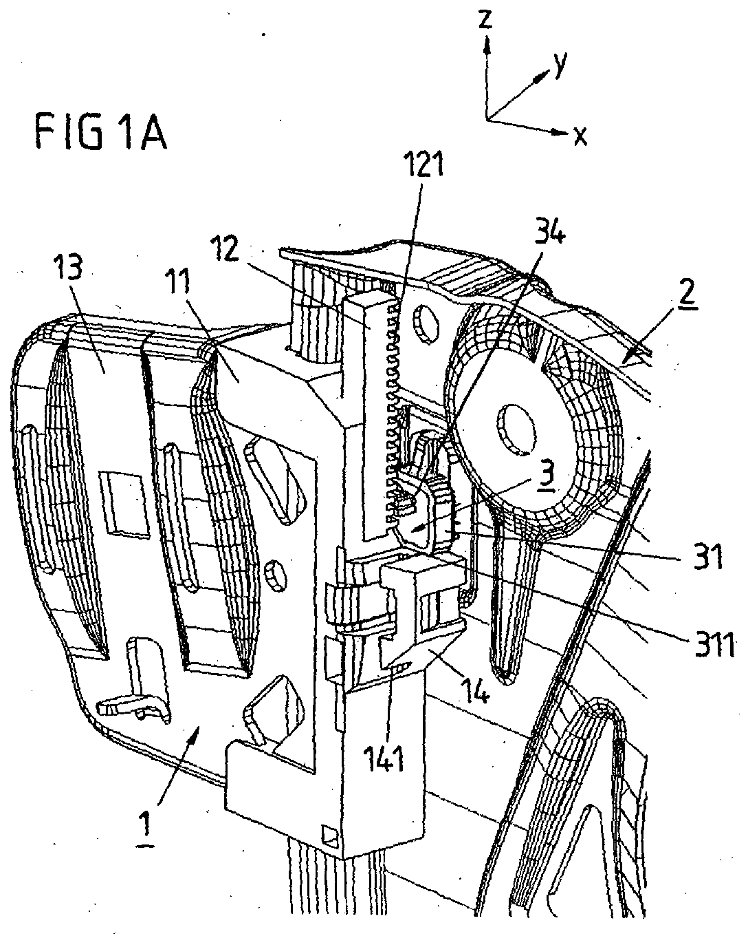
- Figuren 1 a bis 1c
- ein erstes Ausführungsbeispiel für eine erfindungsgemäße Verstelleinrichtung, und zwar in einer dreidimensionalen Darstellung,
- Figur 2
- ein Ausführungsbeispiel für ein aktives Sensorteil der Verstelleinrichtung gemäß den Figuren 1a bis 1c,
- Figur 3
- ein Ausführungsbeispiel für ein Sensorelement des aktiven Sensorteils gemäß der Figur 2,
- Figuren 4a, 4b, 4c
- Detailansichten der relativen Lage des passiven Sensorteils relativ zum aktiven Sensorteil bei der Verstelleinrichtung gemäß den Figuren 1a bis 1c,
- Figur 5
- ein zweites Ausführungsbeispiel für eine erfindungsgemäße Verstelleinrichtung,
- Figuren 6
- ein drittes Ausführungsbeispiel für eine erfindungsgemäße Verstelleinrichtung.
- 1
- Mitnehmer
- 2
- Führungsschiene
- 3
- Aktives Sensorteil
- 7
- Aktives Sensorteil
- 8
- Aktives Sensorteil
- 11
- Gleiter (Gleitbereich)
- 12
- Passives Sensorteil
- 13; 13'
- Klemmbacken (Befestigungsbereich für Fensterscheibe)
- 14
- Nippelkammer
- 31
- Gehäuse
- 32
- Clipselement
- 33
- Elektronik
- 34
- Sensorelement
- 71
- Hall-Sensor
- 72
- Elektronikschaltung
- 81
- Sensoren
- 111
- Führungsschlitze mit L-förmigen Querschnitt
- 121
- Profil
- 122
- Trägerteil
- 123, 124
- Sensorspuren
- 125
- Ausnehmungen
- 131
- Schraube
- 141
- Ausnehmungen in der Nippelkammer
- 311
- Anschlagsfläche
Claims (33)
- Verstelleinrichtung für ein Kraftfahrzeug zum Verstellen eines beweglichen Elements (1) der Verstelleinrichtung mit einem Sensorsystem mit mindestens einem aktiven Sensorteil (3) und mit mindestens einem passiven Sensorteil (12),
dadurch gekennzeichnet, dass das aktive Sensorteil (3) ein ortsfester kapazitiver Sensor ist und das passive Sensorteil (12) einen Bestandteil des beweglichen Elements (1) bildet. - Verstelleinrichtung nach einem der vorangehenden Ansprüche, dadurch gekennzeichnet, dass das passive Sensorteil (12) einen integralen Bestandteil des beweglichen Elements (1) bildet.
- Verstelleinrichtung nach Anspruch 2, dadurch gekennzeichnet, dass das passive Sensorteil (12) an das bewegliche Element (1) einstückig angeformt ist.
- Verstelleinrichtung nach einem der vorangehenden Ansprüche, dadurch gekennzeichnet, dass das passive Sensorteil (12) ein kapazitätsveränderndes Profil (121) aufweist.
- Verstelleinrichtung nach Anspruch 4, dadurch gekennzeichnet, dass das Profil (121) kammförmig oder sinusförmig ist.
- Verstelleinrichtung nach Anspruch 4, dadurch gekennzeichnet, dass das Profil zumindest einen monoton ansteigenden oder zumindest einen monoton abfallenden Verlauf aufweist.
- Verstelleinrichtung nach einem der vorangehenden Ansprüche, dadurch gekennzeichnet, dass das passive Sensorteil (12) zumindest zwei Sensorspuren (123,124) aufweist.
- Verstelleinrichtung nach einem der vorangehenden Ansprüche, dadurch gekennzeichnet, dass das Profil (121) in einem Kunststoffmaterial ausgebildet ist.
- Verstelleinrichtung nach Anspruch 8, dadurch gekennzeichnet, dass das Kunststoffmaterial auf ein, insbesondere metallisches Trägerteil (122) auf- oder angespritzt ist, insbesondere unter Bildung eines Outsert-Teiles.
- Verstelleinrichtung nach einem der vorangehenden Ansprüche, dadurch gekennzeichnet, dass das Trägerteil (122) derart ausgeführt ist, dass es bei einem Vorbeiführen des passiven Sensorteils (12) am aktiven Sensorteil (3) das elektrische Feld im Bereich des aktiven Sensorteiles (3) unbeeinflusst lässt.
- Verstelleinrichtung nach einem der vorangehenden Ansprüche, dadurch gekennzeichnet, dass das Trägerteil (122) ebenfalls ein kapazitätsveränderndes Profil aufweist.
- Verstelleinrichtung nach einem der vorangehenden Ansprüche, dadurch gekennzeichnet, dass das aktive Sensorteil (12) an einem karosseriefesten Trägerelement (2) mittels eines Clipselements (32) aufgeklippst ist, wobei das Clipselement (32) vorzugsweise einstückig mit einem Gehäuse (31) des aktiven Sensorteiles verbunden und weiterhin vorzugsweise aus Kunststoff ist.
- Verstelleinrichtung nach einem der vorangehenden Ansprüche, dadurch gekennzeichnet, dass das Gehäuse (31) des aktiven Sensorteils (3) zumindest eine Anschlagfläche (311) für das bewegliche Element (1) bildet, an die das bewegliche Element (1) zumindest in einer seiner beiden Endlagen anschlägt.
- Verstelleinrichtung nach einem der vorangehenden Ansprüche, dadurch gekennzeichnet, dass das Sensorsystem eine Auswerteeinrichtung, insbesondere eine Elektronikschaltung (72), aufweist, die das Sensorsignal des aktiven Sensorteiles (3) auswertet, wobei die Auswerteeinrichtung (72) vorzugsweise derart ausgestaltet ist, dass sie aus dem Sensorsignal des aktiven Sensorteiles (3) ein analoges oder digitales Messsignal bildet, das die absolute oder relative Position des beweglichen Elements (1) angibt.
- Verstelleinrichtung nach Anspruch 14, dadurch gekennzeichnet, dass die Auswerteeinrichtung (72) ortsfest befestigt ist, wobei die Auswerteeinrichtung (72) vorzugsweise in dem Gehäuse (31) des aktiven Sensorteiles (3) untergebracht ist.
- Verstelleinrichtung nach einem der vorangehenden Ansprüche 14 oder 15, dadurch gekennzeichnet, dass die Auswerteeinrichtung (72) über zumindest ein Kabel mit einer mit einem Antrieb der Verstelleinrichtung verbundenen Steuereinrichtung der Verstelleinrichtung in Verbindung steht und dass die Steuereinrichtung derart ausgestaltet ist, dass sie das analoge oder digitale Messsignal der Auswerteeinrichtung (72) auswertet und die Ansteuerung des Antriebs unter Berücksichtigung der absoluten oder relativen Position des beweglichen Elements vornimmt, wobei vorzugsweise das mindestens eine Kabel und ein Gehäuse der Auswerteeinrichtung (72) wasserdicht verbunden sind.
- Verstelleinrichtung nach Anspruch 16, dadurch gekennzeichnet, dass die Auswerteeinrichtung (72) in dem Gehäuse (31) des aktiven Sensorteiles (3) untergebracht ist und das Gehäuse (31) des aktiven Sensorteiles (3) und das Kabel wasserdicht verbunden sind.
- Verstelleinrichtung nach Anspruch 17, dadurch gekennzeichnet, dass die wasserdichte Verbindung zwischen dem Kabel und dem Gehäuse der Auswerteeinrichtung (72) bzw. dem Gehäuse (31) des aktiven Sensorteiles (3) bewirkt ist, indem das dem Gehäuse (31) zugewandte Ende des Kabels sowie das Gehäuse (31) gemeinsam mit Kunststoff umspritzt sind.
- Verstelleinrichtung nach einem der vorangehenden Ansprüche, dadurch gekennzeichnet, dass dadurch gekennzeichnet, dass die Verstelleinrichtung ein Fensterheber ist und ein zur Befestigung der Fensterscheibe dienender Befestigungsbereich (13) des Mitnehmers (1) - insbesondere beispielsweise eine Klemmbacke (13) des Befestigungsbereichs - aus Metall besteht und durch Kunststoffumspritzen mit einem von der Führungsschiene (2) des Fensterhebers geführten Gleitbereich (11) des Mitnehmers (1) verbunden ist, wobei an dem Gleitbereich (11) das passive Sensorteil (12) einstückig angeformt ist.
- Verstelleinrichtung für ein Kraftfahrzeug zum Verstellen eines beweglichen Elements der Verstelleinrichtung mit einem aktiven und einem passiven Sensorteil, dadurch gekennzeichnet, das die Verstelleinrichtung ein Fensterheber ist, an dessen Mitnehmer (1) für die Fensterscheibe als passives Sensorteil ein magnetfeldveränderndes Element angeordnet ist.
- Verstelleinrichtung nach Anspruch 20, dadurch gekennzeichnet, dass das passive Sensorteil (12) ein integraler Bestandteil des Mitnehmers (1) ist.
- Verstelleinrichtung nach einem der vorangehenden Ansprüche 20 oder 21, dadurch gekennzeichnet, dass das passive Sensorteil (12) einstückig mit dem Mitnehmer (1) verbunden ist.
- Verstelleinrichtung nach einem der vorangehenden Ansprüche 20 bis 22, dadurch gekennzeichnet, dass das passive Sensorteil derart ausgestaltet ist, dass es das von dem aktiven Sensorteil generierte Magnetfeld verändert.
- Verstelleinrichtung nach einem der vorangehenden Ansprüche 20 bis 22, dadurch gekennzeichnet, dass das passive Sensorteil (12) zumindest einen permanentmagnetischen Bereich aufweist, dessen Magnetfeld von dem aktiven Sensorteil (7) erfasst wird.
- Verstelleinrichtung nach einem der vorangehenden Ansprüche 20 bis 24, dadurch gekennzeichnet, dass das Profil des passiven Sensorteiles kammförmig oder sinusförmig ist.
- Verstelleinrichtung nach einem der vorangehenden Ansprüche 20 bis 24, dadurch gekennzeichnet, dass das Profil des passiven Sensorteiles zumindest einen monoton ansteigenden oder abfallenden Verlauf aufweist.
- Verstelleinrichtung nach einem der vorangehenden Ansprüche 20 bis 26, dadurch gekennzeichnet, dass das passive Sensorteil periodisch angeordnete, äquidistante Magnetpole mit wechselnder Magnetfeldausrichtung aufweist.
- Verstelleinrichtung nach einem der vorangehenden Ansprüche 20 bis 27, dadurch gekennzeichnet, dass das passive Sensorteil zumindest zwei Sensorspuren aufweist, die vorzugsweise derart zueinander angeordnet sind, dass eine Messung der absoluten Position auch bei Stillstand des beweglichen Elements möglich ist.
- Verstelleinrichtung nach einem der vorangehenden Ansprüche 20 bis 28, dadurch gekennzeichnet, dass das aktive Sensorteil (7) einen magnetoresistiven Sensor, insbesondere einen Hall-Sensor (71) aufweist.
- Verstelleinrichtung nach Anspruch 29, dadurch gekennzeichnet, dass der Hall-Sensor (71) elektrisch oder magnetisch vorgespannt ist.
- Verstelleinrichtung nach einem der vorangehenden Ansprüche 20 bis 30, dadurch gekennzeichnet, dass die Magneteigenschaften des passiven Sensorteiles über seine Länge derart variieren, dass die radial gerichteten Magnetfeldlinien in Längsrichtung des Sensorteils kontinuierlich oder segmentiert winkelverdreht ausgerichtet sind.
- Verstelleinrichtung nach einem der vorangehenden Ansprüche 20 bis 31, dadurch gekennzeichnet, dass das passive Sensorteil ein Spritzgussteil umfasst, in dem Magnetmaterial eingespritzt ist.
- Verstelleinrichtung nach Anspruch 32, dadurch gekennzeichnet, dass Magnetmaterial nach dem Spritzgießen durch ein Magnetfeld magnetisch ausgerichtet ist.
Applications Claiming Priority (2)
| Application Number | Priority Date | Filing Date | Title |
|---|---|---|---|
| DE10340203 | 2003-08-28 | ||
| DE10340203A DE10340203A1 (de) | 2003-08-28 | 2003-08-28 | Verstelleinrichtung für ein Kraftfahrzeug |
Publications (2)
| Publication Number | Publication Date |
|---|---|
| EP1514990A2 true EP1514990A2 (de) | 2005-03-16 |
| EP1514990A3 EP1514990A3 (de) | 2010-04-14 |
Family
ID=34129611
Family Applications (1)
| Application Number | Title | Priority Date | Filing Date |
|---|---|---|---|
| EP04020231A Withdrawn EP1514990A3 (de) | 2003-08-28 | 2004-08-26 | Verstelleinrichtung für ein Kraftfahrzeug |
Country Status (3)
| Country | Link |
|---|---|
| US (1) | US20050083039A1 (de) |
| EP (1) | EP1514990A3 (de) |
| DE (1) | DE10340203A1 (de) |
Cited By (1)
| Publication number | Priority date | Publication date | Assignee | Title |
|---|---|---|---|---|
| DE102014110664A1 (de) * | 2014-07-29 | 2016-02-04 | Hella Kgaa Hueck & Co. | Stellvorrichtung für die Bewegung eines Stellgliedes |
Families Citing this family (7)
| Publication number | Priority date | Publication date | Assignee | Title |
|---|---|---|---|---|
| DE202005004528U1 (de) * | 2005-03-14 | 2006-07-27 | Brose Fahrzeugteile Gmbh & Co. Kommanditgesellschaft, Coburg | Positionsmess-System für ein verstellbares Kraftfahrzeugteil |
| DE202005007536U1 (de) * | 2005-05-09 | 2006-09-28 | Brose Schließsysteme GmbH & Co.KG | Funktionseinheit eines Kraftfahrzeugs |
| DE102006030930A1 (de) * | 2006-07-05 | 2008-01-10 | Wilhelm Karmann Gmbh | Überwachungsvorrichtung für ein Cabrioletverdeck, Verfahren zur Überwachung eines Cabrioletverdecks sowie ein Cabrioletfahrzeug |
| US7800379B2 (en) * | 2007-12-12 | 2010-09-21 | Delphi Technologies, Inc. | Fuel sensor |
| DE202009009028U1 (de) * | 2009-07-01 | 2010-12-30 | Brose Fahrzeugteile Gmbh & Co. Kommanditgesellschaft, Hallstadt | Kapazitive Sensoreinheit |
| DE102011106937A1 (de) * | 2011-07-08 | 2013-01-10 | Brose Fahrzeugteile Gmbh & Co. Kommanditgesellschaft, Hallstadt | Drehzahlerfassung eines Fentserheberantriebs |
| DE102014219008A1 (de) * | 2014-09-22 | 2016-03-24 | Continental Teves Ag & Co. Ohg | Energieversorgungsnetz |
Family Cites Families (8)
| Publication number | Priority date | Publication date | Assignee | Title |
|---|---|---|---|---|
| DE9013491U1 (de) * | 1990-09-25 | 1990-11-29 | Siemens AG, 8000 München | Steuergerät zur Steuerung des Antriebsmotors eines Verschlusses einer Öffnung |
| US5169112A (en) * | 1991-08-26 | 1992-12-08 | Milsco Manufacturing Company | Electronic suspension vehicle seat |
| US5404673A (en) * | 1992-06-26 | 1995-04-11 | Koito Manufacturing Co., Ltd. | Power window apparatus with safety device |
| DE19724009A1 (de) * | 1997-06-09 | 1998-12-10 | Bosch Gmbh Robert | Verstellantrieb, insbesondere für ein Schiebedach eines Kraftfahrzeugs |
| DE19910636A1 (de) * | 1999-03-10 | 2000-09-14 | Inst Mikrostrukturtechnologie | Längenmeßsystem, bestehend aus einem oder mehreren magnetischen Maßstäben |
| US6936984B2 (en) * | 2000-08-28 | 2005-08-30 | Lear Corporation | Method and system for detecting the position of a power window of a vehicle |
| DE10229369B4 (de) * | 2001-07-10 | 2006-09-21 | Keiper Gmbh & Co.Kg | Sensor für einen Fahrzeugsitz |
| FR2829523B1 (fr) * | 2001-09-11 | 2004-03-12 | Meritor Light Vehicle Sys Ltd | Leve-vitre a dispositif anti-pincement a capteur optique |
-
2003
- 2003-08-28 DE DE10340203A patent/DE10340203A1/de not_active Withdrawn
-
2004
- 2004-08-26 EP EP04020231A patent/EP1514990A3/de not_active Withdrawn
- 2004-08-30 US US10/929,330 patent/US20050083039A1/en not_active Abandoned
Cited By (2)
| Publication number | Priority date | Publication date | Assignee | Title |
|---|---|---|---|---|
| DE102014110664A1 (de) * | 2014-07-29 | 2016-02-04 | Hella Kgaa Hueck & Co. | Stellvorrichtung für die Bewegung eines Stellgliedes |
| US10539954B2 (en) | 2014-07-29 | 2020-01-21 | HELLA GmbH & Co. KGaA | Description of an actuating device for moving an actuator |
Also Published As
| Publication number | Publication date |
|---|---|
| DE10340203A1 (de) | 2005-03-24 |
| EP1514990A3 (de) | 2010-04-14 |
| US20050083039A1 (en) | 2005-04-21 |
Similar Documents
| Publication | Publication Date | Title |
|---|---|---|
| DE102009021225B4 (de) | Öffnungs- und Schliessvorrichtung und Verfahren zum Herstellen eines Sensorstützelements | |
| EP1917167B9 (de) | Elektromotorischer hilfsantrieb für fahrzeuge | |
| DE102007034099A1 (de) | Vorrichtung zur berührungslosen Erfassung von Relativpositionen zweier zueinander bewegbarer Teile | |
| EP1894877A2 (de) | Türantrieb für eine automatische Tür | |
| WO2001072563A1 (de) | Elektromotor insbesondere wischermotor zum wischen einer scheibe eines kraftfahrzeugs | |
| EP1129268B1 (de) | Vorrichtung zum erfassen der verstellung translatorisch bewegter verstelleinrichtungen in fahrzeugen | |
| EP2659318B1 (de) | Verfahren und vorrichtung zum bereitstellen einer bewegungsangabe, insbesondere für eine blockiererkennung eines schliesssystems | |
| EP1514990A2 (de) | Verstelleinrichtung für ein Kraftfahrzeug | |
| EP1722060B1 (de) | Funktionseinheit eines Kraftfahrzeugs | |
| EP1360092B1 (de) | Gerät zum anbringen an eine fahrzeugtüre | |
| DE102009008160A1 (de) | Tor für eine Garage und Garage mit einem entsprechenden Tor | |
| EP1739266B1 (de) | Steuerungssystem für Fensterheber eines Kraftfahrzeugs | |
| EP3178701B1 (de) | Vorrichtung zur positionsbestimmung | |
| EP0917643A1 (de) | Wegsensor | |
| EP1279216A1 (de) | Elektromechanische antriebsvorrichtung | |
| EP1097845A2 (de) | Aussenrückspiegel mit Positionssensor | |
| DE112010003114T5 (de) | Gleichstrom-Elektromotor, insbesondere für Bewegungen an Kraftfahrzeugen wieFensterheber, Sitzversteller, Scheibenwischer und dergleichen | |
| DE102004063512B4 (de) | Fensterscheibe für ein Kraftfahrzeug | |
| DE102014211559B4 (de) | Bestimmen einer Schwenkposition einer Fahrzeugtür | |
| DE19643947C5 (de) | Verschlußeinrichtung für eine Kraftfahrzeugtür mit Türschloß und Schloßhalter | |
| DE10329045B4 (de) | Einrichtung zur Ermittlung mindestens einer Endlagenposition eines Antriebsgliedes, insbesondere eines druckmittelbetriebenen Linear- oder Drehantriebes | |
| DE10249845B4 (de) | Steuerungsvorrichtung für Fahrzeug-Dachsysteme | |
| DE102004021382B4 (de) | Befestigungselement für einen Sensorkopf | |
| EP1447498B1 (de) | Türgriffanordnung für eine Kraftfahrzeugtür | |
| DE102014115673A1 (de) | Antriebsvorrichtung und Antriebsverfahren |
Legal Events
| Date | Code | Title | Description |
|---|---|---|---|
| PUAI | Public reference made under article 153(3) epc to a published international application that has entered the european phase |
Free format text: ORIGINAL CODE: 0009012 |
|
| AK | Designated contracting states |
Kind code of ref document: A2 Designated state(s): AT BE BG CH CY CZ DE DK EE ES FI FR GB GR HU IE IT LI LU MC NL PL PT RO SE SI SK TR |
|
| AX | Request for extension of the european patent |
Extension state: AL HR LT LV MK |
|
| RIN1 | Information on inventor provided before grant (corrected) |
Inventor name: RIETDIJK, DALIBOR Inventor name: KULLMANN, ACHIM |
|
| PUAL | Search report despatched |
Free format text: ORIGINAL CODE: 0009013 |
|
| AK | Designated contracting states |
Kind code of ref document: A3 Designated state(s): AT BE BG CH CY CZ DE DK EE ES FI FR GB GR HU IE IT LI LU MC NL PL PT RO SE SI SK TR |
|
| AX | Request for extension of the european patent |
Extension state: AL HR LT LV MK |
|
| RIC1 | Information provided on ipc code assigned before grant |
Ipc: E05F 15/00 20060101ALI20100310BHEP Ipc: E05F 15/10 20060101ALI20100310BHEP Ipc: E05F 15/16 20060101AFI20050119BHEP |
|
| AKY | No designation fees paid | ||
| STAA | Information on the status of an ep patent application or granted ep patent |
Free format text: STATUS: THE APPLICATION IS DEEMED TO BE WITHDRAWN |
|
| 18D | Application deemed to be withdrawn |
Effective date: 20101015 |
|
| REG | Reference to a national code |
Ref country code: DE Ref legal event code: R108 Effective date: 20110405 Ref country code: DE Ref legal event code: 8566 |