EP1098046A2 - Verkleidungssystem für Fassaden und Dächer von Bauwerken - Google Patents
Verkleidungssystem für Fassaden und Dächer von Bauwerken Download PDFInfo
- Publication number
- EP1098046A2 EP1098046A2 EP00123256A EP00123256A EP1098046A2 EP 1098046 A2 EP1098046 A2 EP 1098046A2 EP 00123256 A EP00123256 A EP 00123256A EP 00123256 A EP00123256 A EP 00123256A EP 1098046 A2 EP1098046 A2 EP 1098046A2
- Authority
- EP
- European Patent Office
- Prior art keywords
- bolt
- area
- support
- locking area
- carrier element
- Prior art date
- Legal status (The legal status is an assumption and is not a legal conclusion. Google has not performed a legal analysis and makes no representation as to the accuracy of the status listed.)
- Granted
Links
- 238000005253 cladding Methods 0.000 title claims abstract description 17
- 239000000945 filler Substances 0.000 claims abstract description 6
- 229910052751 metal Inorganic materials 0.000 claims abstract description 4
- 239000002184 metal Substances 0.000 claims abstract description 4
- 238000007789 sealing Methods 0.000 claims description 7
- 229910052782 aluminium Inorganic materials 0.000 claims description 3
- XAGFODPZIPBFFR-UHFFFAOYSA-N aluminium Chemical compound [Al] XAGFODPZIPBFFR-UHFFFAOYSA-N 0.000 claims description 3
- 238000001125 extrusion Methods 0.000 claims description 3
- 229910000838 Al alloy Inorganic materials 0.000 claims description 2
- 239000000463 material Substances 0.000 description 5
- 238000005516 engineering process Methods 0.000 description 4
- 239000011521 glass Substances 0.000 description 4
- 238000010276 construction Methods 0.000 description 3
- 239000005340 laminated glass Substances 0.000 description 3
- 230000007797 corrosion Effects 0.000 description 2
- 238000005260 corrosion Methods 0.000 description 2
- 238000005553 drilling Methods 0.000 description 2
- 238000004519 manufacturing process Methods 0.000 description 2
- 238000000034 method Methods 0.000 description 2
- 230000000284 resting effect Effects 0.000 description 2
- 229910000831 Steel Inorganic materials 0.000 description 1
- 238000010521 absorption reaction Methods 0.000 description 1
- 238000005452 bending Methods 0.000 description 1
- 230000001419 dependent effect Effects 0.000 description 1
- 230000006866 deterioration Effects 0.000 description 1
- 238000011161 development Methods 0.000 description 1
- 230000018109 developmental process Effects 0.000 description 1
- 238000006073 displacement reaction Methods 0.000 description 1
- 238000009826 distribution Methods 0.000 description 1
- 230000010354 integration Effects 0.000 description 1
- 238000003754 machining Methods 0.000 description 1
- 150000002739 metals Chemical class 0.000 description 1
- 230000002787 reinforcement Effects 0.000 description 1
- 239000010959 steel Substances 0.000 description 1
Images


Classifications
-
- E—FIXED CONSTRUCTIONS
- E04—BUILDING
- E04B—GENERAL BUILDING CONSTRUCTIONS; WALLS, e.g. PARTITIONS; ROOFS; FLOORS; CEILINGS; INSULATION OR OTHER PROTECTION OF BUILDINGS
- E04B2/00—Walls, e.g. partitions, for buildings; Wall construction with regard to insulation; Connections specially adapted to walls
- E04B2/88—Curtain walls
- E04B2/96—Curtain walls comprising panels attached to the structure through mullions or transoms
- E04B2/965—Connections of mullions and transoms
-
- E—FIXED CONSTRUCTIONS
- E04—BUILDING
- E04B—GENERAL BUILDING CONSTRUCTIONS; WALLS, e.g. PARTITIONS; ROOFS; FLOORS; CEILINGS; INSULATION OR OTHER PROTECTION OF BUILDINGS
- E04B9/00—Ceilings; Construction of ceilings, e.g. false ceilings; Ceiling construction with regard to insulation
- E04B9/06—Ceilings; Construction of ceilings, e.g. false ceilings; Ceiling construction with regard to insulation characterised by constructional features of the supporting construction, e.g. cross section or material of framework members
- E04B9/12—Connections between non-parallel members of the supporting construction
-
- E—FIXED CONSTRUCTIONS
- E04—BUILDING
- E04D—ROOF COVERINGS; SKY-LIGHTS; GUTTERS; ROOF-WORKING TOOLS
- E04D3/00—Roof covering by making use of flat or curved slabs or stiff sheets
- E04D3/02—Roof covering by making use of flat or curved slabs or stiff sheets of plane slabs, slates, or sheets, or in which the cross-section is unimportant
- E04D3/06—Roof covering by making use of flat or curved slabs or stiff sheets of plane slabs, slates, or sheets, or in which the cross-section is unimportant of glass or other translucent material; Fixing means therefor
- E04D3/08—Roof covering by making use of flat or curved slabs or stiff sheets of plane slabs, slates, or sheets, or in which the cross-section is unimportant of glass or other translucent material; Fixing means therefor with metal glazing bars
- E04D2003/0868—Mutual connections and details of glazing bars
Definitions
- the invention relates to a cladding system for facades and roofs of buildings according to the preamble of claim 1.
- Such a facade system is known from DE 196 06 906 A1.
- the facade system in screw-plug technology is for vertical, diagonal and horizontal Cladding of buildings is provided and consists of metallic hollow profiles as posts, which are joined to a frame system with transversely connecting transoms.
- Filling elements are arranged on the frame system, the load of which is on the posts and latch attachable support elements is added.
- the filling elements on the carrier elements For example, as filling elements Metal plates or laminated glass pane elements are used.
- the filling elements are detachably connected to the frame via external retaining strips. Around Longitudinal grooves are used to ensure an insulating fastening of the filling elements the frame and the retaining strips arranged elastic sealing elements.
- the support element is multifunctional in the known facade system, that is, the Carrier element fulfills both a connecting function for the attachment of posts and latch as well as a carrier function for the filling elements resting thereon.
- the carrier element can be screwed to the transom and post using fastening screws.
- a glass support by means of a Attach the dowel system to the transom.
- the latch has the filling elements on it facing side has a central longitudinal groove into which an expansion plug for Engagement comes, the flanks of which are inserted by an inserted socket are spread outside that they come to rest on the beveled groove flanks.
- a thin plate is provided, which has two Pin of the dowel system comes to rest.
- the invention includes the technical teaching that the support element of a cladding system essentially has a flat basic shape and from a support area for carrying the filling elements and a locking area with a there is at least one recess arranged for attachment to the bolt, wherein the bolt has at least one longitudinal slot into which the locking area of the support element can be inserted, which by moving along of the longitudinal slot can be locked in such a way that the recess is locked with the bar forms.
- the advantage of the support element held on the bolt via the longitudinal slot lies in that the attachment of the support element without the use of screws or other fastening aids. This reduces the assembly effort. Since in the solution according to the invention for fastening the carrier element the entire profile depth of the bolt is available, the support element a high load-bearing capacity. Furthermore, the relatively thin contact area enables in connection with a large usable support surface for carrying the Filler the absorption of a high weight, so that the assembly of large-area filling elements on a narrow frame system can. For example, with the solution according to the invention on one narrow frame profile of only 45 mm wide, a large-area filling element, which requires a glass rebate height of 20 mm. The contact area of the The support element is dimensioned accordingly to 5 mm thickness. At this width a reliable screw connection would no longer be possible.
- the locking area of the carrier element when plugged in, cooperates with the guide section of the bolt holder in such a way that the bolt holder is simultaneously moved by displacement within the longitudinal slot, so that the plug pin engages in the associated bore on the post .
- the carrier element also performs a locking function for the bolt during assembly.
- the resulting functional integration further simplifies the construction and assembly of the cladding system. The assembly of the support element and the locking of the transom on the post is therefore possible in a single assembly step.
- the support area of the support element serves as a handle for manual locking.
- the support area is designed in such a way that a continuous surface is available for contact with the filler element resting on it and the locking area is made up of at least two similar partial surfaces There is one recess each, the partial surfaces being insertable into respectively assigned longitudinal slots in the bolt. In this respect, at least two fastening points for the bolt are created for the carrier element.
- the continuous contact area on the part of the filling element allows optimal load distribution.
- Another measure improving the invention is that at least a side flank of the recess on the locking area is chamfered is.
- the carrier element is preferably made of aluminum or an aluminum alloy manufactured. This choice of material enables simple production through use of the extrusion process. However, other materials are also preferred Metals - conceivable for the production of the carrier element, provided that it is the required one Have material strength. Because of the high bending stress of the Carrier element at the boundary between the support area and the locking area material reinforcements can be an advantage here. Preferably can furthermore, the support area of the carrier element has a smaller thickness than the locking area because the locking area as stated above can be formed in partial areas. The associated deterioration Stability relationships balanced over the greater thickness. Because the support area of the carrier element is not divided into partial areas, here is a smaller thickness permissible, which is also desirable in view of the limited space available.
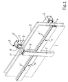
- Post 1 and transom 2 exist from a steel sheet that is bent and then welded lengthways the abutting edges is designed to form a hollow profile.
- the filling elements 3 are designed as laminated glass pane elements and via outer holding strips 4, 4 'by means of fastening means, not shown here, on the mullion 1 or transom 2 kept detachable.
- the holding strips 4, 4 ' are provided with an outer cover 5, 5'.
- the cover 5, 5 ' is detachable by screws 10, 10' with the holding strips 4, 4 ' connected.
- An outer seal is between the retaining strip 4 and the filling element 3 6 and an inner seal 7 between the filling element 3 and the bolt 2 arranged.
- This sealing arrangement is both on the post 1 and on the transom 2 provided analogously.
- the inner seal 7 is designed like a rail, around the support surface 8 facing the filling elements 3 on the mullion 1 and transom 2 to ensure reliable protection against corrosion.
- the contact surface 8 of the post 1 lies in a plane with a corresponding one Bolt contact surface 2.
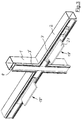
- the post 1 positioned vertically according to FIG. 2 is used for mounting the horizontal Bolt 2 used in screw-plug technology of the bolt holder 11.
- the latch holder 11 has two socket pins 12 and a guide section 13.
- the guide section 13 is designed so that it with little play in the end area of the latch 2 can be inserted.
- the socket pins 12 come to corresponding Bores 14 on the post 1 for engagement to hold the latch 2 on the post 1.
- the contact surface 8 a through hole 16 through which the screw 17 can be inserted in order to screw in the threaded basic bore 15.
- a carrier element 18 is via longitudinal slots 19, 19 'in the contact surface 8 of the bolt 2 (which is also in the Seal 7 are provided) attached. Fastening the flat support element 18 on the bolt 2 is carried out via a locking area 20, which in the longitudinal slots 19 can be inserted.
- the locking area 20 of the carrier element 18 acts simultaneously in the inserted state together with the guide portion 13 of the bolt holder 11 such that Moving within the longitudinal slot 19, 19 'of the latch holder 11 is also movable is so that the socket pin 12 in the associated bore 14 on the post 1 for engagement is coming.
- the carrier element 18 also has a support area 21 for Wear the filling element, not shown here.
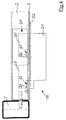
- FIG 3 shows the facade system in the assembly state described above forth.
- the contact area 21 of the carrier element 18 is orthogonal to the Contact surface 8 of the bolt 2 aligned.
- the seal 7 is in the intersection area arranged between the post 1 and the bar 2 so that both with respect to of the post 1 and also with respect to the transom 2 results in a continuous channel.
- the Orthogonality between the support area 21 and the contact surface 8 is shown by an attachment 22 formed on the carrier element 18 is ensured, which is orthogonal extends to the support area 21 and comes to rest on the seal 7.
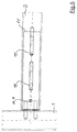
- the two are on the locking region 20 of the carrier element 18 longitudinal slots 19, 19 'arranged centrally on the contact surface 8 of the bolt 2 intended.
- the longitudinal slots 19, 19 ' are on the line of symmetry of the contact surface 8.
- the through hole 16 in the bolt is also on the line of symmetry 2 provided, in the assembled state shown here with the threaded basic bore 15 brought into alignment in the internal latch holder 11 is, so that a fixation in this position by means of not shown here Screw can be done.
- the carrier element 8 shown separately in FIG. 6 consists of aluminum and is through Extrusion presses are manufactured with subsequent machining.
- the lock serving together with the wall of the bar, not shown here Recesses 24 and 24 'on the two partial surfaces 25 and 25' has on the Approach 22 opposite side a beveled side flank 23 or 23 '.
- the front parallel area grips first the recess 24, 24 '.
- the subsequent area of the beveled side 23, 23 ' causes the shoulder 22 to be pressed in the direction of the one not shown here Poetry.
- the subsequent parallel side area of the recess holds the lock in this position.
Landscapes
- Engineering & Computer Science (AREA)
- Architecture (AREA)
- Civil Engineering (AREA)
- Structural Engineering (AREA)
- Physics & Mathematics (AREA)
- Electromagnetism (AREA)
- Load-Bearing And Curtain Walls (AREA)
- Rod-Shaped Construction Members (AREA)
- Joining Of Building Structures In Genera (AREA)
- Greenhouses (AREA)
- Building Environments (AREA)
- Conveying And Assembling Of Building Elements In Situ (AREA)
Abstract
Description
Um eine in statischer Hinsicht besonders zuverlässige Befestigung des Trägerelementes am Riegel zu gewährleisten kann es von Vorteil sein, wenn der Auflagebereich derart ausgestaltet ist, daß für den Kontakt zum darauf ruhenden Füllelement eine durchgehende Fläche zur Verfügung steht und der Verriegelungsbereich aus mindestens zwei gleichartigen Teilflächen mit je einer Ausnehmung besteht, wobei die Teilflächen in jeweils zugeordnete Längsschlitze im Riegel einsteckbar sind. Insoweit entstehen für das Trägerelement mindestens zwei Befestigungspunkte zum Riegel. Der durchgängige Auflagebereich auf Seiten des Füllelementes gestattet eine optimale Lastverteilung.
- Fig. 1
- eine perspektivische Außenansicht eines Verkleidungssystems im Kreuzungsbereich zwischen Pfosten und Riegel,
- Fig. 2
- eine Explosionsdarstellung der Elemente des Verkleidungssystems,
- Fig. 3
- eine perspektivische Ansicht des Verkleidungssystems im Kreuzungsbereich zwischen Pfosten und Riegel im teilweise zusammengebauten Zustand,
- Fig. 4
- eine Seitenansicht eines Trägerelementes im montierten Zustand am Riegel,
- Fig. 5
- eine Draufsicht auf die das Trägerelement nach Figur 4 aufnehmende Längsschlitze im Riegel,
- Fig. 6
- eine Seitenansicht sowie eine Profilansicht des Trägerelementes,
- 1
- Pfosten
- 2
- Riegel
- 3
- Füllelement
- 4
- Halteleiste
- 5
- Abdeckung
- 6
- Dichtung
- 7
- Dichtung
- 8
- Auflagefläche
- 9
- Seitenfläche
- 10
- Schraube
- 11
- Riegelhalter
- 12
- Steckbolzen
- 13
- Führungsabschnitt
- 14
- Bohrung
- 15
- Gewindegrundbohrung
- 16
- Durchgangsbohrung
- 17
- Schraube
- 18
- Trägerelement
- 19
- Längsschlitz
- 20
- Verriegelungsbereich
- 21
- Auflagebereich
- 22
- Ansatz
- 23
- Seitenflanke
- 24
- Ausnehmung
- 25
- Teilfläche
Claims (9)
- Verkleidungssystem für Fassaden und Dächer von Bauwerken mit aus im wesentlichen rechteckigen metallischen Hohlprofilen gebildeten Pfosten (1) und Riegeln (2), die ein Rahmensystem für Füllelemente (3) bilden und über mindestens einen jeden Riegel (2) zugeordneten Riegelhalter (11) lösbar miteinander verbunden sind, der mittels mindestens eines Steckbolzens 12) in eine zugeordnete Bohrung (14) am Pfosten (1) eingreift und der über einen im Endbereich des Riegels (2) verschiebbaren und fixierbaren Führungsabschnitt (13) verfügt, wobei die parallel zum Rahmensystem gerichtete Last der Füllelemente (3) ein zumindest am Riegel (2) befestigbares Trägerelement (18) aufnimmt und wobei zur lösbaren Befestigung der Füllelemente (3) am Rahmensystem außen angeordnete Halteleisten (4) vorgesehen sind, die durch Befestigungsmittel mit dem Rahmensystem über Dichtelemente (7) zusammenwirken,
dadurch gekennzeichnet,
daß das Tragerelement (18) im wesentlichen eine flache Grundform aufweist und aus einem Auflagebereich (21) zum Tragen des Füllelementes (3) sowie einem Verriegelungsbereich (20) mit einer zumindest einseitig angeordneten Ausnehmung (24, 24') zur Befestigung am Riegel (2) besteht, wobei der Riegel (2) über mindestens einen Längsschlitz (19, 19') verfügt, in den der Verriegelungsbereich (20) des Trägerelementes (18) einsteckbar ist, welches durch Verschieben entlang des Längsschlitzes (19, 19') derart arretierbar ist, daß die Ausnehmung (24, 24') eine Verriegelung mit dem Riegel (2) bildet. - Verkleidungssystem nach Anspruch 1,
dadurch gekennzeichnet,
daß der Verriegelungsbereich (20) des Trägerelementes (18) im eingesteckten Zustand mit dem Führungsabschnitt (13) des Riegelhalters (11) derart zusammenwirkt, daß durch das Verschieben innerhalb des Längsschlitzes (19, 19') gleichzeitig der Riegelhalter (11) bewegbar ist, so daß der Steckbolzen (12) in die zugeordnete Bohrung (14) am Pfosten (1) zum Eingriff kommt. - Verkleidungssystem nach Anspruch 1,
dadurch gekennzeichnet,
daß der Auflagebereich (21) des Trägerelementes (18) eine durchgehende Fläche aufweist und der Verriegelungsbereich (20) aus mindestens zwei gleichartigen Teilflächen (25, 25') mit je einer Ausnehmung (24, 24') besteht, wobei die Teilflächen (25, 25') in jeweils zugeordnete Längsschlitze (19, 19') im Riegel (2) einsteckbar sind. - Verriegelungssystem nach Anspruch 1,
dadurch gekennzeichnet,
daß zumindest eine Seitenflanke (23, 23') der Ausnehmung (24, 24') am Verriegelungsbereich (20) derart abgeschrägt ausgebildet ist, daß durch das Verschieben entlang des Längsschlitzes (19, 19') ein zwischen dem Verriegelungsbereich (20) sowie dem Auflagebereich (21) gelegener Ansatz (22) dichtend an einem auf dem Riegel (2) angeordneten Dichtelement (7) drückbar ist, so daß der Längsschlitz (19, 19') nach außen hin abgedichtet ist. - Verkleidungssystem nach Anspruch 1,
dadurch gekennzeichnet,
daß das Trägerelement (18) in der verriegelten Position mittels eines zwischen dem Riegel (2) und dem Riegelhalter 11) wirkenden Befestigungselementes fixierbar ist. - Fassadensystem nach Anspruch 1,
dadurch gekennzeichnet,
daß das Befestigungselement eine Schraube ist, die über eine Durchgangsbohrung (16) am Riegel (2) im Riegelhalter 11) mittels einer Gewindebohrung (15) einschraubbar ist. - Fassadensystem nach Anspruch 1,
dadurch gekennzeichnet,
daß das Trägerlement (18) aus Aluminium oder einer Aluminiumlegierung besteht und durch Strangpressen hergestellt ist. - Verkleidungssystem nach Anspruch 1,
dadurch gekennzeichnet,
daß der Auflagebereich (21) des Trägerelementes (18) eine geringere Dicke als der Verriegelungsbereich (20) aufweist. - Verkleidungssystem nach Anspruch 8,
dadurch gekennzeichnet,
daß der Auflagebereich (21) eine Dicke von 3 bis 6 mm und der Verriegelungsbereich (20) eine Dicke von 6 bis 10 mm aufweist.
Applications Claiming Priority (2)
| Application Number | Priority Date | Filing Date | Title |
|---|---|---|---|
| DE19953557A DE19953557C1 (de) | 1999-11-03 | 1999-11-03 | Verkleidungssystem für Fassaden und Dächer von Bauwerken |
| DE19953557 | 1999-11-03 |
Publications (3)
| Publication Number | Publication Date |
|---|---|
| EP1098046A2 true EP1098046A2 (de) | 2001-05-09 |
| EP1098046A3 EP1098046A3 (de) | 2002-02-13 |
| EP1098046B1 EP1098046B1 (de) | 2004-10-13 |
Family
ID=7928215
Family Applications (1)
| Application Number | Title | Priority Date | Filing Date |
|---|---|---|---|
| EP00123256A Expired - Lifetime EP1098046B1 (de) | 1999-11-03 | 2000-10-26 | Verkleidungssystem für Fassaden und Dächer von Bauwerken |
Country Status (4)
| Country | Link |
|---|---|
| EP (1) | EP1098046B1 (de) |
| AT (1) | ATE279603T1 (de) |
| DE (2) | DE19953557C1 (de) |
| PL (1) | PL206659B1 (de) |
Cited By (6)
| Publication number | Priority date | Publication date | Assignee | Title |
|---|---|---|---|---|
| WO2002029174A1 (de) * | 2000-09-30 | 2002-04-11 | SCHÜCO International KG | Im glasfalz einer fassade oder eines lichtdaches vorgesehene trägereinheit |
| WO2007137805A1 (de) * | 2006-05-30 | 2007-12-06 | Rehau Ag + Co | Konstruktionsanordnung |
| EP2862984A1 (de) * | 2013-10-17 | 2015-04-22 | Herbert Lacker | Fachwerk zur Verglasung eines Gebäudes |
| EP3006638A1 (de) | 2014-10-09 | 2016-04-13 | Herbert Lacker | Riegel für ein Fachwerk zur Verglasung eines Gebäudes |
| WO2018126329A1 (de) * | 2017-01-09 | 2018-07-12 | Jansen Ag | Tragstruktur für fassadenelemente |
| FR3110628A1 (fr) * | 2020-05-20 | 2021-11-26 | Vulcain | Cloison vitrée coupe-feu |
Families Citing this family (2)
| Publication number | Priority date | Publication date | Assignee | Title |
|---|---|---|---|---|
| CN106988461A (zh) * | 2017-03-23 | 2017-07-28 | 合肥协耀玻璃制品有限公司 | 一种高层建筑楼体安装幕墙玻璃的钢架 |
| DE102020132662A1 (de) | 2020-12-08 | 2022-06-09 | Raico Bautechnik Gmbh | T-Verbindung für Pfosten-Riegel-Konstruktionen und Pfosten- Riegel-Konstruktion mit einer derartigen T-Verbindung |
Citations (1)
| Publication number | Priority date | Publication date | Assignee | Title |
|---|---|---|---|---|
| DE19606906A1 (de) | 1996-02-13 | 1997-08-14 | Mannesmann Ag | Fassadensystem für vertikale, diagonale und horizontale Verkleidungen von Bauten |
Family Cites Families (4)
| Publication number | Priority date | Publication date | Assignee | Title |
|---|---|---|---|---|
| US4428171A (en) * | 1982-03-12 | 1984-01-31 | Atlantic Richfield Company | Thermal storefront system |
| DE8816686U1 (de) * | 1988-04-11 | 1990-03-22 | Josef Gartner & Co, 8883 Gundelfingen | Vorrichtung zur Befestigung von Verglasungen |
| DE3838957A1 (de) * | 1988-11-17 | 1990-05-23 | Forster Ag Hermann | Isolierende verbindungsvorrichtung fuer bauplatten |
| SE503591C2 (sv) * | 1994-12-16 | 1996-07-15 | Pk Staalprofil Ab | Anordning vid profilsystem |
-
1999
- 1999-11-03 DE DE19953557A patent/DE19953557C1/de not_active Expired - Lifetime
-
2000
- 2000-10-26 EP EP00123256A patent/EP1098046B1/de not_active Expired - Lifetime
- 2000-10-26 AT AT00123256T patent/ATE279603T1/de not_active IP Right Cessation
- 2000-10-26 DE DE2000508213 patent/DE50008213D1/de not_active Expired - Fee Related
- 2000-11-02 PL PL343654A patent/PL206659B1/pl not_active IP Right Cessation
Patent Citations (1)
| Publication number | Priority date | Publication date | Assignee | Title |
|---|---|---|---|---|
| DE19606906A1 (de) | 1996-02-13 | 1997-08-14 | Mannesmann Ag | Fassadensystem für vertikale, diagonale und horizontale Verkleidungen von Bauten |
Cited By (8)
| Publication number | Priority date | Publication date | Assignee | Title |
|---|---|---|---|---|
| WO2002029174A1 (de) * | 2000-09-30 | 2002-04-11 | SCHÜCO International KG | Im glasfalz einer fassade oder eines lichtdaches vorgesehene trägereinheit |
| HRP20030236B1 (hr) * | 2000-09-30 | 2011-12-31 | Sch�Co International Kg | Jedinica za nošenje predviđena za ostakljivanje fasade ili prozirnog krova |
| WO2007137805A1 (de) * | 2006-05-30 | 2007-12-06 | Rehau Ag + Co | Konstruktionsanordnung |
| EP2862984A1 (de) * | 2013-10-17 | 2015-04-22 | Herbert Lacker | Fachwerk zur Verglasung eines Gebäudes |
| EP3006638A1 (de) | 2014-10-09 | 2016-04-13 | Herbert Lacker | Riegel für ein Fachwerk zur Verglasung eines Gebäudes |
| WO2018126329A1 (de) * | 2017-01-09 | 2018-07-12 | Jansen Ag | Tragstruktur für fassadenelemente |
| EP3875703A1 (de) * | 2017-01-09 | 2021-09-08 | Jansen AG | Dichtungsprofil für eine tragstruktur für fassadenelemente |
| FR3110628A1 (fr) * | 2020-05-20 | 2021-11-26 | Vulcain | Cloison vitrée coupe-feu |
Also Published As
| Publication number | Publication date |
|---|---|
| EP1098046A3 (de) | 2002-02-13 |
| EP1098046B1 (de) | 2004-10-13 |
| DE19953557C1 (de) | 2001-07-12 |
| ATE279603T1 (de) | 2004-10-15 |
| DE50008213D1 (de) | 2004-11-18 |
| PL206659B1 (pl) | 2010-09-30 |
| PL343654A1 (en) | 2001-05-07 |
Similar Documents
| Publication | Publication Date | Title |
|---|---|---|
| EP1352134B1 (de) | Riegel-pfosten-konstruktion | |
| EP0436869B1 (de) | Verbindung des Stosses zwischen Riegel und Pfosten an einem Traggerippe für eine oder an einer Fassadenwand | |
| DE3415344C2 (de) | Schnellbaugerippe, insbesondere aus Stahl als tragende Konstruktion für Decken- und Wandplatten eines Gebäudes | |
| DE3112746A1 (de) | "profilstabfoermiges bauelement fuer gebaeude" | |
| EP0722023A2 (de) | Aus Profilstäben gebildete miteinander verbundene Pfosten und Riegel | |
| EP1098046B1 (de) | Verkleidungssystem für Fassaden und Dächer von Bauwerken | |
| EP1680562B1 (de) | Stützrahmenwerk für eine fassade | |
| EP0298328B1 (de) | Fassadenwand | |
| DE29912697U1 (de) | Verkleidungssystem für Fassaden und Dächer von Bauwerken | |
| EP1647649A2 (de) | Fassadenbefestigungssystem | |
| DE202008014975U1 (de) | T-Verbindung zwischen einem Pfosten- und Riegelprofil | |
| EP0725202A1 (de) | Bewehrung an Türen oder Fenstern | |
| WO2022084167A1 (de) | Plattenverbindungssystem | |
| DE102020106891B4 (de) | T-Verbindung zwischen einem Pfosten- und Riegelprofil und Pfosten-Riegel-Konstruktion mit einer derartigen T-Verbindung | |
| EP1836359A1 (de) | Modulare fassade für gebäude, glasauflagedichtung und schraube | |
| DE10229272A1 (de) | Stoßverbinder zum winkeligen Verbinden von Hohlprofilen | |
| EP4575119B1 (de) | T-verbindung und verfahren zur montage einer t-verbindung | |
| EP3150792B1 (de) | Thermisch getrenntes profilrahmensystem | |
| DE10043444B4 (de) | Fenster- oder Türrahmen mit einem verschraubten Verbinder | |
| DE10043443B4 (de) | Fenster- oder Türrahmen mit einem Verbinder | |
| DE4041161A1 (de) | Verbindungsvorrichtung fuer eine sprossenkonstruktion und verfahren zur herstellung einer sprossenkonstruktion mit dieser verbindungsvorrichtung | |
| DE3401936A1 (de) | Riegelhalter fuer eine fassadenwandkonstruktion aus rohrprofilen | |
| DE102023129393A1 (de) | Abstützelement und Gebäudeverkleidung | |
| DE29801925U1 (de) | Kämpferverbinder | |
| DE2718651A1 (de) | Bauelement in form eines fensters oder einer tuer |
Legal Events
| Date | Code | Title | Description |
|---|---|---|---|
| PUAI | Public reference made under article 153(3) epc to a published international application that has entered the european phase |
Free format text: ORIGINAL CODE: 0009012 |
|
| 17P | Request for examination filed |
Effective date: 20001026 |
|
| AK | Designated contracting states |
Kind code of ref document: A2 Designated state(s): AT BE CH CY DE DK ES FI FR GB GR IE IT LI LU MC NL PT SE |
|
| AX | Request for extension of the european patent |
Free format text: AL;LT;LV;MK;RO;SI |
|
| PUAL | Search report despatched |
Free format text: ORIGINAL CODE: 0009013 |
|
| AK | Designated contracting states |
Kind code of ref document: A3 Designated state(s): AT BE CH CY DE DK ES FI FR GB GR IE IT LI LU MC NL PT SE |
|
| AX | Request for extension of the european patent |
Free format text: AL;LT;LV;MK;RO;SI |
|
| AKX | Designation fees paid |
Free format text: AT BE CH CY DE DK ES FI FR GB GR IE IT LI LU MC NL PT SE |
|
| 17Q | First examination report despatched |
Effective date: 20031020 |
|
| GRAP | Despatch of communication of intention to grant a patent |
Free format text: ORIGINAL CODE: EPIDOSNIGR1 |
|
| GRAS | Grant fee paid |
Free format text: ORIGINAL CODE: EPIDOSNIGR3 |
|
| GRAA | (expected) grant |
Free format text: ORIGINAL CODE: 0009210 |
|
| AK | Designated contracting states |
Kind code of ref document: B1 Designated state(s): AT BE CH CY DE DK ES FI FR GB GR IE IT LI LU MC NL PT SE |
|
| PG25 | Lapsed in a contracting state [announced via postgrant information from national office to epo] |
Ref country code: IT Free format text: LAPSE BECAUSE OF FAILURE TO SUBMIT A TRANSLATION OF THE DESCRIPTION OR TO PAY THE FEE WITHIN THE PRESCRIBED TIME-LIMIT;WARNING: LAPSES OF ITALIAN PATENTS WITH EFFECTIVE DATE BEFORE 2007 MAY HAVE OCCURRED AT ANY TIME BEFORE 2007. THE CORRECT EFFECTIVE DATE MAY BE DIFFERENT FROM THE ONE RECORDED. Effective date: 20041013 Ref country code: FI Free format text: LAPSE BECAUSE OF FAILURE TO SUBMIT A TRANSLATION OF THE DESCRIPTION OR TO PAY THE FEE WITHIN THE PRESCRIBED TIME-LIMIT Effective date: 20041013 Ref country code: SE Free format text: LAPSE BECAUSE OF FAILURE TO SUBMIT A TRANSLATION OF THE DESCRIPTION OR TO PAY THE FEE WITHIN THE PRESCRIBED TIME-LIMIT Effective date: 20041013 Ref country code: NL Free format text: LAPSE BECAUSE OF FAILURE TO SUBMIT A TRANSLATION OF THE DESCRIPTION OR TO PAY THE FEE WITHIN THE PRESCRIBED TIME-LIMIT Effective date: 20041013 Ref country code: FR Free format text: LAPSE BECAUSE OF FAILURE TO SUBMIT A TRANSLATION OF THE DESCRIPTION OR TO PAY THE FEE WITHIN THE PRESCRIBED TIME-LIMIT Effective date: 20041013 Ref country code: GB Free format text: LAPSE BECAUSE OF FAILURE TO SUBMIT A TRANSLATION OF THE DESCRIPTION OR TO PAY THE FEE WITHIN THE PRESCRIBED TIME-LIMIT Effective date: 20041013 Ref country code: IE Free format text: LAPSE BECAUSE OF FAILURE TO SUBMIT A TRANSLATION OF THE DESCRIPTION OR TO PAY THE FEE WITHIN THE PRESCRIBED TIME-LIMIT Effective date: 20041013 Ref country code: CY Free format text: LAPSE BECAUSE OF FAILURE TO SUBMIT A TRANSLATION OF THE DESCRIPTION OR TO PAY THE FEE WITHIN THE PRESCRIBED TIME-LIMIT Effective date: 20041013 |
|
| REG | Reference to a national code |
Ref country code: GB Ref legal event code: FG4D Free format text: NOT ENGLISH |
|
| REG | Reference to a national code |
Ref country code: CH Ref legal event code: EP |
|
| PG25 | Lapsed in a contracting state [announced via postgrant information from national office to epo] |
Ref country code: AT Free format text: LAPSE BECAUSE OF NON-PAYMENT OF DUE FEES Effective date: 20041026 Ref country code: LU Free format text: LAPSE BECAUSE OF NON-PAYMENT OF DUE FEES Effective date: 20041026 |
|
| PG25 | Lapsed in a contracting state [announced via postgrant information from national office to epo] |
Ref country code: MC Free format text: LAPSE BECAUSE OF NON-PAYMENT OF DUE FEES Effective date: 20041031 Ref country code: LI Free format text: LAPSE BECAUSE OF NON-PAYMENT OF DUE FEES Effective date: 20041031 Ref country code: CH Free format text: LAPSE BECAUSE OF NON-PAYMENT OF DUE FEES Effective date: 20041031 Ref country code: BE Free format text: LAPSE BECAUSE OF NON-PAYMENT OF DUE FEES Effective date: 20041031 |
|
| REG | Reference to a national code |
Ref country code: IE Ref legal event code: FG4D Free format text: GERMAN |
|
| REF | Corresponds to: |
Ref document number: 50008213 Country of ref document: DE Date of ref document: 20041118 Kind code of ref document: P |
|
| PG25 | Lapsed in a contracting state [announced via postgrant information from national office to epo] |
Ref country code: DK Free format text: LAPSE BECAUSE OF FAILURE TO SUBMIT A TRANSLATION OF THE DESCRIPTION OR TO PAY THE FEE WITHIN THE PRESCRIBED TIME-LIMIT Effective date: 20050113 Ref country code: GR Free format text: LAPSE BECAUSE OF FAILURE TO SUBMIT A TRANSLATION OF THE DESCRIPTION OR TO PAY THE FEE WITHIN THE PRESCRIBED TIME-LIMIT Effective date: 20050113 |
|
| PG25 | Lapsed in a contracting state [announced via postgrant information from national office to epo] |
Ref country code: ES Free format text: LAPSE BECAUSE OF FAILURE TO SUBMIT A TRANSLATION OF THE DESCRIPTION OR TO PAY THE FEE WITHIN THE PRESCRIBED TIME-LIMIT Effective date: 20050124 |
|
| NLV1 | Nl: lapsed or annulled due to failure to fulfill the requirements of art. 29p and 29m of the patents act | ||
| BERE | Be: lapsed |
Owner name: RP TECHNIK G.M.B.H. PROFILSYSTEME Effective date: 20041031 |
|
| GBV | Gb: ep patent (uk) treated as always having been void in accordance with gb section 77(7)/1977 [no translation filed] |
Effective date: 20041013 |
|
| REG | Reference to a national code |
Ref country code: IE Ref legal event code: FD4D |
|
| REG | Reference to a national code |
Ref country code: CH Ref legal event code: PL |
|
| PLBE | No opposition filed within time limit |
Free format text: ORIGINAL CODE: 0009261 |
|
| STAA | Information on the status of an ep patent application or granted ep patent |
Free format text: STATUS: NO OPPOSITION FILED WITHIN TIME LIMIT |
|
| 26N | No opposition filed |
Effective date: 20050714 |
|
| EN | Fr: translation not filed | ||
| BERE | Be: lapsed |
Owner name: *RP TECHNIK G.M.B.H. PROFILSYSTEME Effective date: 20041031 |
|
| PG25 | Lapsed in a contracting state [announced via postgrant information from national office to epo] |
Ref country code: PT Free format text: LAPSE BECAUSE OF NON-PAYMENT OF DUE FEES Effective date: 20050313 |
|
| PGFP | Annual fee paid to national office [announced via postgrant information from national office to epo] |
Ref country code: DE Payment date: 20071029 Year of fee payment: 8 |
|
| PG25 | Lapsed in a contracting state [announced via postgrant information from national office to epo] |
Ref country code: DE Free format text: LAPSE BECAUSE OF NON-PAYMENT OF DUE FEES Effective date: 20090501 |