EP1098074A2 - Moteur à allumage commandé et à injection directe de carburant - Google Patents
Moteur à allumage commandé et à injection directe de carburant Download PDFInfo
- Publication number
- EP1098074A2 EP1098074A2 EP00309306A EP00309306A EP1098074A2 EP 1098074 A2 EP1098074 A2 EP 1098074A2 EP 00309306 A EP00309306 A EP 00309306A EP 00309306 A EP00309306 A EP 00309306A EP 1098074 A2 EP1098074 A2 EP 1098074A2
- Authority
- EP
- European Patent Office
- Prior art keywords
- fuel
- piston
- cylinder head
- lower wall
- combustion
- Prior art date
- Legal status (The legal status is an assumption and is not a legal conclusion. Google has not performed a legal analysis and makes no representation as to the accuracy of the status listed.)
- Withdrawn
Links
- 238000002485 combustion reaction Methods 0.000 title claims abstract description 59
- 238000002347 injection Methods 0.000 title abstract description 10
- 239000007924 injection Substances 0.000 title abstract description 10
- 239000000446 fuel Substances 0.000 claims abstract description 87
- 239000007921 spray Substances 0.000 claims abstract description 35
- 238000009736 wetting Methods 0.000 claims abstract description 13
- 230000008020 evaporation Effects 0.000 claims description 5
- 238000001704 evaporation Methods 0.000 claims description 5
- 230000007423 decrease Effects 0.000 claims description 2
- 238000000034 method Methods 0.000 claims 4
- 239000000203 mixture Substances 0.000 abstract description 14
- 230000035515 penetration Effects 0.000 abstract description 10
- 230000015572 biosynthetic process Effects 0.000 abstract description 5
- 229930195733 hydrocarbon Natural products 0.000 abstract description 5
- 150000002430 hydrocarbons Chemical class 0.000 abstract description 5
- 239000004071 soot Substances 0.000 abstract description 5
- 238000013517 stratification Methods 0.000 abstract description 3
- 239000004215 Carbon black (E152) Substances 0.000 description 2
- 239000003595 mist Substances 0.000 description 2
- QVGXLLKOCUKJST-UHFFFAOYSA-N atomic oxygen Chemical compound [O] QVGXLLKOCUKJST-UHFFFAOYSA-N 0.000 description 1
- 230000009286 beneficial effect Effects 0.000 description 1
- 239000007789 gas Substances 0.000 description 1
- 230000003993 interaction Effects 0.000 description 1
- 230000007246 mechanism Effects 0.000 description 1
- 239000001301 oxygen Substances 0.000 description 1
- 229910052760 oxygen Inorganic materials 0.000 description 1
Images
Classifications
-
- F—MECHANICAL ENGINEERING; LIGHTING; HEATING; WEAPONS; BLASTING
- F02—COMBUSTION ENGINES; HOT-GAS OR COMBUSTION-PRODUCT ENGINE PLANTS
- F02B—INTERNAL-COMBUSTION PISTON ENGINES; COMBUSTION ENGINES IN GENERAL
- F02B23/00—Other engines characterised by special shape or construction of combustion chambers to improve operation
- F02B23/08—Other engines characterised by special shape or construction of combustion chambers to improve operation with positive ignition
- F02B23/10—Other engines characterised by special shape or construction of combustion chambers to improve operation with positive ignition with separate admission of air and fuel into cylinder
- F02B23/104—Other engines characterised by special shape or construction of combustion chambers to improve operation with positive ignition with separate admission of air and fuel into cylinder the injector being placed on a side position of the cylinder
-
- F—MECHANICAL ENGINEERING; LIGHTING; HEATING; WEAPONS; BLASTING
- F02—COMBUSTION ENGINES; HOT-GAS OR COMBUSTION-PRODUCT ENGINE PLANTS
- F02B—INTERNAL-COMBUSTION PISTON ENGINES; COMBUSTION ENGINES IN GENERAL
- F02B23/00—Other engines characterised by special shape or construction of combustion chambers to improve operation
- F02B23/08—Other engines characterised by special shape or construction of combustion chambers to improve operation with positive ignition
- F02B23/10—Other engines characterised by special shape or construction of combustion chambers to improve operation with positive ignition with separate admission of air and fuel into cylinder
- F02B2023/106—Tumble flow, i.e. the axis of rotation of the main charge flow motion is horizontal
-
- F—MECHANICAL ENGINEERING; LIGHTING; HEATING; WEAPONS; BLASTING
- F02—COMBUSTION ENGINES; HOT-GAS OR COMBUSTION-PRODUCT ENGINE PLANTS
- F02B—INTERNAL-COMBUSTION PISTON ENGINES; COMBUSTION ENGINES IN GENERAL
- F02B2275/00—Other engines, components or details, not provided for in other groups of this subclass
- F02B2275/48—Tumble motion in gas movement in cylinder
-
- Y—GENERAL TAGGING OF NEW TECHNOLOGICAL DEVELOPMENTS; GENERAL TAGGING OF CROSS-SECTIONAL TECHNOLOGIES SPANNING OVER SEVERAL SECTIONS OF THE IPC; TECHNICAL SUBJECTS COVERED BY FORMER USPC CROSS-REFERENCE ART COLLECTIONS [XRACs] AND DIGESTS
- Y02—TECHNOLOGIES OR APPLICATIONS FOR MITIGATION OR ADAPTATION AGAINST CLIMATE CHANGE
- Y02T—CLIMATE CHANGE MITIGATION TECHNOLOGIES RELATED TO TRANSPORTATION
- Y02T10/00—Road transport of goods or passengers
- Y02T10/10—Internal combustion engine [ICE] based vehicles
- Y02T10/12—Improving ICE efficiencies
Definitions
- This invention relates to stratified-charge combustion systems for direct-injection spark-ignited engines.
- One object of these systems is to achieve charge stratification through direct fuel injection into the combustion chamber with minimum wall wetting by the fuel and with an overall lean but locally burnable fuel-air mixture directed to the spark plug.
- Several attempts have been made to accomplish this by reorganising the combustion chamber configuration, modifying the in-cylinder air flow, and optimising fuel injection with respect to timing, location and spray characteristics.
- U.S. Patent No. 5,711,269 discusses a reverse tumble combustion system with a spherical bowl in the top of the piston near the intake valve side and with a fuel injector in the intake valve side.
- U.S. Patent No. 5,259,348 shows a stratified-charge combustion system with a swirl air flow and a bowl in the piston at the intake valve side.
- the present invention provides a unique combustion chamber design and system which minimises wall wetting and provides an overall lean air-fuel mixture at an optimum position in the combustion chamber in order to secure improved fuel economy and reduced emissions.
- the inventive system utilises a piston with a spherical or nearly spherical bowl configuration located near or adjacent to the exhaust valve side of the combustion chamber.
- the intake port design provides a normal tumble flow of intake air.
- the injector is located on the intake valve side of the combustion chamber and a small recess can be provided at the edge of the piston bowl in order to avoid contact with the injector and/or avoid impingement of the fuel spray outside the bowl.
- the distance for penetration of the fuel spray is increased due to the positioning of the piston bowl.
- the spray droplets have more time to evaporate before they can contact the far wall of the piston bowl.
- the direction of the fuel spray is in opposition to the direction of the tumble inlet air flow at certain points in the combustion cycle. This further slows the fuel droplet movement and allows more time for evaporation.
- the in- cylinder tumble air flow moves the vapour and fuel cloud in the direction of the spark plug located adjacent the centre of the cylinder head.
- a lower fuel spray penetration rate can be utilised.
- the present invention minimises wall wetting and overly rich fuel regions. This reduces soot formation and reduces the amount of unburned hydrocarbons. Also, the invention provides improved ignitability of the injected fuel and reduces cycle-by-cycle variations and misfirings.
- the present invention provides a combustion system with a piston bowl on the exhaust valve side of the combustion chamber, an in-cylinder normal tumble air flow, and an injector in the intake valve side of the combustion chamber in order to form improved charge stratification and ignition in the combustion chamber of a direct-injection spark-ignited (DISI) engine.
- DISI direct-injection spark-ignited
- the present invention forms an ignitable air-fuel mixture around the spark plug gap with less wetting of the piston by the fuel due to the extended distance for spray penetration, the reduction in the spray penetration rate by a counter air flow against the fuel spray, and by moving the fuel vapour upwardly to the spark plug by the tumble air flow.
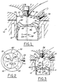
- Figures 1 and 2 illustrate the principal concepts of the present invention, with Figure 1 being a cross-section of a combustion chamber design showing the piston and cylinder head with their various affiliated features, and Figure 2 being a top view of the piston illustrating one preferred shape and position of the combustion chamber bowl.
- the inventive combustion chamber system is designated by the numeral 10 in Figure 1. It is to be noted that other shapes and sizes of combustion chamber bowls could be utilised in accordance with the present invention. For example, the bowl could also be an elliptical shape with a major axis aligned with a vertical plane through the cylinder axis.
- the system 10 includes an engine 12 of which only a portion is shown, the engine having a plurality of pistons and cylinder chambers or bores, only one of which is shown for illustrative purposes.
- the system 10 includes a piston 14 and a cylinder head 16, the piston 14 being positioned in a cylinder chamber or bore 18 in the engine 12.
- the cylinder head 16 has a lower wall with a pair of slanted wall portions 20 and 22, and a relatively flat or horizontal wall portion 24 positioned between them.
- a spark plug 26 is positioned in the middle wall portion 24 near the central axis 28 of the cylinder bore 18.
- One or more intake ports 30 are positioned on the intake-side of the cylinder 18 along wall portion 22.
- one or more exhaust ports or outlets 32 are positioned in the exhaust side of the cylinder 18 and along wall portion 20.
- the spark plug 26 can be of any conventional design and is positioned to extend slightly into the cylinder bore 18.
- the inlet ports 30 and exhaust ports 32 can be of any standard design and closed by conventional intake and exhaust valves and valving systems (not shown).
- a fuel injector 34 is positioned in the lower wall of the cylinder head 16 on the intake valve side of the cylinder bore 18, as shown in Figure 1.
- the injector can be of any conventional design and is operated by a conventional spray injector control and system (not shown).
- the piston 14 has an upper or top wall or surface 40 which is angled generally to conform with the angles of the wall portions 20 and 22 of the lower wall of the cylinder head 16.
- the piston 14 also has a combustion bowl 42 in its upper surface which is used to mix the air and fuel and direct it toward the spark plug 26.
- the piston bowl 42 which is depicted has a spherical or nearly spherical bowl shape. As mentioned earlier, other shapes and sizes of combustion chamber bowls can be utilised.
- the bowl 42 is positioned such that the majority of its area is situated on the exhaust-valve side of the cylinder bore 18. In this regard, the centre 44 of the piston bowl 42 is preferably positioned 5 to 15 millimetres toward the exhaust side of the central axis 28 of the cylinder bore 18. This distance is indicated by the dimension D in Figures 1 and 2.
- a small recess or groove 46 can also be provided on the top of the piston 14 if desired.
- the recess 46 may be necessary to avoid interference with the end of the injector 34, or to ensure that all of the fuel spray from injector 34 enters the piston bowl 42 and does not impinge upon the upper surface 40.
- the fuel spray penetration rate at the injector outlet is preferably within the range of 20-40 meters per second (m/s) at the injector outlet. This penetration rate is lower than that of most conventional fuel systems. The lower spray penetration rate provides an improved shape of the fuel zone.
- FIG. 3 The design of the intake port 30 provides a normal tumble flow of intake air in the cylinder bore 18 and combustion chamber. This is shown by the arrows 50 in Figure 3.
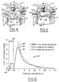
- Figures 3-5 illustrate various steps or sequences in the injection and combustion cycle of fuel and air in the cylinder bore 18 and combustion chamber.
- the fuel spray 52 is injected by the fuel injector 34 in a direction toward the far wall 42' of the combustion chamber bowl 42 in the piston 14.
- the fuel spray from the injector diverges as it leaves the injector and forms a fuel mist cloud in the general shape shown in Figure 3 and indicated by the reference number 52.
- the air-fuel cloud or mixture 54 is directed toward the spark plug 26 where it is ignited. This is shown in Figure 5.
- the ignition of the air-fuel mixture helps propel the piston in its downward stroke in the cylinder in a standard manner.
- the burned air-fuel mixture is exhausted through the exhaust ports 32 in a conventional manner.
- the distance from the fuel injector 34 to the farthest wall 42' of the piston bowl 42 is increased over most conventional systems.
- the distance for free penetration of the fuel spray in the cylinder bore is increased.
- fuel spray droplets have more time to evaporate before they contact the surface of the piston and wet the piston wall.
- the direction of the normal tumble air flow is generally counter or opposite to the fuel being injected by the injector 34. This in turn slows down the movement of the spray droplets and allows for more droplet evaporation. Again, this reduces the wetting of the wall 42' of the piston bowl 42.
- the relative velocity between the fuel droplets from the injector 34 and the air from the inlets 30 is increased. This further promotes the rate of droplet evaporation.
- the relative velocity between the air flow and the fuel spray increases as the speed of the engine increases. This provides enhanced mixing and fuel evaporation with speed.
- the time for mixing of the fuel and air decreases as the speed of the engine increases.
- the in-cylinder tumble flow of air from the inlet ports 30 directs the vapour and fuel cloud 54 upwardly in the cylinder toward the spark plug 26.
- This provides a satisfactory mixture and amount of air and fuel at the spark plug gap and improves ignitability. This in turn reduces cycle-by-cycle variation of the air-fuel cloud or mixture and reduces the chances of misfiring of the engine.
- the various curves of 68, 70 and 72 are all centred around the excess air ratio of 1.0. This is beneficial since it indicates that for various operations of the engine, the fuel distribution versus excess air ratio is relatively consistent and uniform.
Landscapes
- Engineering & Computer Science (AREA)
- Chemical & Material Sciences (AREA)
- Combustion & Propulsion (AREA)
- Mechanical Engineering (AREA)
- General Engineering & Computer Science (AREA)
- Combustion Methods Of Internal-Combustion Engines (AREA)
Applications Claiming Priority (2)
| Application Number | Priority Date | Filing Date | Title |
|---|---|---|---|
| US434347 | 1999-11-05 | ||
| US09/434,347 US6269790B1 (en) | 1999-11-05 | 1999-11-05 | Combustion chamber for DISI engines with exhaust side piston bowl |
Publications (2)
| Publication Number | Publication Date |
|---|---|
| EP1098074A2 true EP1098074A2 (fr) | 2001-05-09 |
| EP1098074A3 EP1098074A3 (fr) | 2002-09-11 |
Family
ID=23723855
Family Applications (1)
| Application Number | Title | Priority Date | Filing Date |
|---|---|---|---|
| EP00309306A Withdrawn EP1098074A3 (fr) | 1999-11-05 | 2000-10-23 | Moteur à allumage commandé et à injection directe de carburant |
Country Status (2)
| Country | Link |
|---|---|
| US (1) | US6269790B1 (fr) |
| EP (1) | EP1098074A3 (fr) |
Cited By (1)
| Publication number | Priority date | Publication date | Assignee | Title |
|---|---|---|---|---|
| EP4198278A1 (fr) * | 2021-12-17 | 2023-06-21 | Volvo Truck Corporation | Moteur à combustion interne de carburant gazeux |
Families Citing this family (14)
| Publication number | Priority date | Publication date | Assignee | Title |
|---|---|---|---|---|
| US6659075B1 (en) * | 1999-06-11 | 2003-12-09 | Hitachi, Ltd. | Cylinder injection engine and method of combusting engine |
| DE19948237A1 (de) * | 1999-10-07 | 2001-04-12 | Bosch Gmbh Robert | Verfahren zum Zumessen von Brennstoff mit einem Brennstoffeinspritzventil |
| JP2003065187A (ja) * | 2001-08-22 | 2003-03-05 | Sanshin Ind Co Ltd | 船外機における燃料供給装置 |
| US6892693B2 (en) * | 2003-02-12 | 2005-05-17 | Bombardier Recreational Products, Inc. | Piston for spark-ignited direct fuel injection engine |
| US6725828B1 (en) | 2003-06-17 | 2004-04-27 | Ford Global Technologies, Llc | Vortex-induced stratification combustion for direct injection spark ignition engines |
| US6945219B2 (en) * | 2004-02-09 | 2005-09-20 | Bombardier Recreational Products Inc. | Dual zone combustion chamber |
| US6971365B1 (en) * | 2004-07-12 | 2005-12-06 | General Motors Corporation | Auto-ignition gasoline engine combustion chamber and method |
| CN101208502A (zh) * | 2005-06-27 | 2008-06-25 | 奥托诺瓦公司 | 燃机 |
| EP2047079A1 (fr) * | 2006-08-04 | 2009-04-15 | Toyota Jidosha Kabushiki Kaisha | Moteur à combustion interne à allumage commandé à injection directe et procédé d'injection de carburant pour ledit moteur |
| US8056531B2 (en) | 2010-06-24 | 2011-11-15 | Ford Global Technologies Llc | Shallow piston bowl and injector spray pattern for a gasoline, direct-injection engine |
| DE102012014193A1 (de) * | 2012-07-18 | 2014-05-15 | Mahle International Gmbh | Kolben für einen Verbrennungsmotor |
| JP6172193B2 (ja) * | 2015-03-24 | 2017-08-02 | マツダ株式会社 | エンジンの吸気装置 |
| JP7585739B2 (ja) * | 2020-11-25 | 2024-11-19 | マツダ株式会社 | エンジンの燃焼室構造 |
| DE102021123461A1 (de) * | 2021-09-10 | 2023-03-16 | Keyou GmbH | Verfahren zum Betrieb einer Verbrennungskraftmaschine, Verbrennungskraftmaschine und Steuereinrichtung |
Citations (2)
| Publication number | Priority date | Publication date | Assignee | Title |
|---|---|---|---|---|
| US5259348A (en) | 1991-06-20 | 1993-11-09 | Toyota Jidosha Kabushiki Kaisha | Direct injection type engine |
| US5711269A (en) | 1995-03-28 | 1998-01-27 | Mitsubishi Jidosha Kogyo Kabushiki Kaisha | In-cylinder injection internal combustion engine |
Family Cites Families (14)
| Publication number | Priority date | Publication date | Assignee | Title |
|---|---|---|---|---|
| US4958604A (en) | 1988-02-10 | 1990-09-25 | Toyota Jidosha Kabushiki Kaisha | Direct fuel injection type spark ignition internal combustion engine |
| JPH0826772B2 (ja) | 1988-02-26 | 1996-03-21 | トヨタ自動車株式会社 | 火花点火筒内噴射エンジン |
| US5245975A (en) | 1990-11-28 | 1993-09-21 | Toyota Jidosha Kabushiki Kaisha | Direct injection type internal combustion engine |
| DE69401829T2 (de) | 1993-04-05 | 1997-09-18 | Isuzu Motors Ltd | Brennkraftmaschine mit mehreren Einlassventilen |
| JP3300910B2 (ja) | 1994-02-04 | 2002-07-08 | マツダ株式会社 | 直噴式ディーゼルエンジン |
| JP3163906B2 (ja) | 1994-07-27 | 2001-05-08 | トヨタ自動車株式会社 | 筒内噴射式火花点火機関 |
| US5735240A (en) | 1995-06-19 | 1998-04-07 | Yamaha Hatsudoki Kabushiki Kaisha | Direct injected engine |
| US6009849A (en) * | 1996-08-12 | 2000-01-04 | Mazda Motor Corporation | Direct fuel injection engine |
| JPH10281039A (ja) * | 1997-04-02 | 1998-10-20 | Hitachi Ltd | 燃料噴射装置とその制御方法 |
| JPH10317975A (ja) * | 1997-05-21 | 1998-12-02 | Nissan Motor Co Ltd | 筒内直接噴射式火花点火機関 |
| JP3325232B2 (ja) * | 1997-09-29 | 2002-09-17 | マツダ株式会社 | 筒内噴射式エンジン |
| AT2432U1 (de) * | 1997-10-16 | 1998-10-27 | Avl List Gmbh | Brennkraftmaschine mit fremdzündung |
| FR2772073B1 (fr) * | 1997-12-08 | 2000-02-04 | Renault | Moteur a combustion interne a allumage commande et a injection directe |
| US6003488A (en) * | 1998-07-15 | 1999-12-21 | Chrysler Corporation | Direct injection spark ignition engine |
-
1999
- 1999-11-05 US US09/434,347 patent/US6269790B1/en not_active Expired - Fee Related
-
2000
- 2000-10-23 EP EP00309306A patent/EP1098074A3/fr not_active Withdrawn
Patent Citations (2)
| Publication number | Priority date | Publication date | Assignee | Title |
|---|---|---|---|---|
| US5259348A (en) | 1991-06-20 | 1993-11-09 | Toyota Jidosha Kabushiki Kaisha | Direct injection type engine |
| US5711269A (en) | 1995-03-28 | 1998-01-27 | Mitsubishi Jidosha Kogyo Kabushiki Kaisha | In-cylinder injection internal combustion engine |
Cited By (1)
| Publication number | Priority date | Publication date | Assignee | Title |
|---|---|---|---|---|
| EP4198278A1 (fr) * | 2021-12-17 | 2023-06-21 | Volvo Truck Corporation | Moteur à combustion interne de carburant gazeux |
Also Published As
| Publication number | Publication date |
|---|---|
| US6269790B1 (en) | 2001-08-07 |
| EP1098074A3 (fr) | 2002-09-11 |
Similar Documents
| Publication | Publication Date | Title |
|---|---|---|
| US5720253A (en) | Direct-injection type spark-ignition internal combustion engine | |
| EP0839997B1 (fr) | Structure de chambre de combustion avec cavité du piston | |
| USRE36500E (en) | Internal combustion engine | |
| US6971365B1 (en) | Auto-ignition gasoline engine combustion chamber and method | |
| US7464687B2 (en) | Direct-injection engine, method of controlling the same, piston used in the same and fuel injection valve used in the same | |
| CN1325777C (zh) | 缸内直喷式火花点火发动机 | |
| US20210040913A1 (en) | Method for operating a spark-ignition internal combustion engine | |
| US5735240A (en) | Direct injected engine | |
| US6269790B1 (en) | Combustion chamber for DISI engines with exhaust side piston bowl | |
| US8056531B2 (en) | Shallow piston bowl and injector spray pattern for a gasoline, direct-injection engine | |
| GB2328976A (en) | Forming a stratified charge in a direct-injection spark-ignition i.c. engine | |
| US10718258B2 (en) | Spark-ignited direct-injection engine combustion systems | |
| EP1069291B1 (fr) | Moteur à injection directe et à allumage commandé | |
| EP1770256B1 (fr) | Moteur à combustion interne à injection directe et à allumage commandé et méthode de l'utilisation | |
| US6799550B2 (en) | Spark-ignition engine having direct fuel injection | |
| US6684848B2 (en) | Direct-injection spark-ignition engine | |
| US20090139485A1 (en) | Direct injection two-stroke engine | |
| US6062192A (en) | Internal combustion engine with spark ignition | |
| EP0990779B1 (fr) | Moteurs à combustion interne à injection directe | |
| US6267096B1 (en) | Three-valve cylinder head system | |
| JPH09280055A (ja) | 直接筒内噴射式火花点火エンジン | |
| JP2841791B2 (ja) | 燃料噴射式内燃機関 | |
| JP2000282864A (ja) | 筒内噴射エンジンの燃焼室構造 | |
| JP2001073779A (ja) | 筒内噴射エンジンの燃焼室構造 | |
| JPH03105017A (ja) | 外部点火による直噴式内燃機関 |
Legal Events
| Date | Code | Title | Description |
|---|---|---|---|
| PUAI | Public reference made under article 153(3) epc to a published international application that has entered the european phase |
Free format text: ORIGINAL CODE: 0009012 |
|
| AK | Designated contracting states |
Kind code of ref document: A2 Designated state(s): AT BE CH CY DE DK ES FI FR GB GR IE IT LI LU MC NL PT SE |
|
| AX | Request for extension of the european patent |
Free format text: AL;LT;LV;MK;RO;SI |
|
| PUAL | Search report despatched |
Free format text: ORIGINAL CODE: 0009013 |
|
| AK | Designated contracting states |
Kind code of ref document: A3 Designated state(s): AT BE CH CY DE DK ES FI FR GB GR IE IT LI LU MC NL PT SE |
|
| AX | Request for extension of the european patent |
Free format text: AL;LT;LV;MK;RO;SI |
|
| 17P | Request for examination filed |
Effective date: 20030128 |
|
| 17Q | First examination report despatched |
Effective date: 20030321 |
|
| AKX | Designation fees paid |
Designated state(s): DE GB SE |
|
| STAA | Information on the status of an ep patent application or granted ep patent |
Free format text: STATUS: THE APPLICATION IS DEEMED TO BE WITHDRAWN |
|
| 18D | Application deemed to be withdrawn |
Effective date: 20030801 |