EP1098130A1 - Tragvorrichtung zur Abstützung von Gegenständen - Google Patents
Tragvorrichtung zur Abstützung von Gegenständen Download PDFInfo
- Publication number
- EP1098130A1 EP1098130A1 EP00123787A EP00123787A EP1098130A1 EP 1098130 A1 EP1098130 A1 EP 1098130A1 EP 00123787 A EP00123787 A EP 00123787A EP 00123787 A EP00123787 A EP 00123787A EP 1098130 A1 EP1098130 A1 EP 1098130A1
- Authority
- EP
- European Patent Office
- Prior art keywords
- support column
- carrying device
- support
- supported
- base leg
- Prior art date
- Legal status (The legal status is an assumption and is not a legal conclusion. Google has not performed a legal analysis and makes no representation as to the accuracy of the status listed.)
- Granted
Links
- 230000002093 peripheral effect Effects 0.000 claims description 2
- 230000000712 assembly Effects 0.000 description 2
- 238000000429 assembly Methods 0.000 description 2
- 230000006978 adaptation Effects 0.000 description 1
- 230000004888 barrier function Effects 0.000 description 1
- 230000015572 biosynthetic process Effects 0.000 description 1
- 238000006243 chemical reaction Methods 0.000 description 1
- 230000006835 compression Effects 0.000 description 1
- 238000007906 compression Methods 0.000 description 1
- 238000006073 displacement reaction Methods 0.000 description 1
- 230000000694 effects Effects 0.000 description 1
- 239000011521 glass Substances 0.000 description 1
- 238000009434 installation Methods 0.000 description 1
- 238000003754 machining Methods 0.000 description 1
- 238000000465 moulding Methods 0.000 description 1
- 230000000087 stabilizing effect Effects 0.000 description 1
Images


Classifications
-
- A—HUMAN NECESSITIES
- A47—FURNITURE; DOMESTIC ARTICLES OR APPLIANCES; COFFEE MILLS; SPICE MILLS; SUCTION CLEANERS IN GENERAL
- A47B—TABLES; DESKS; OFFICE FURNITURE; CABINETS; DRAWERS; GENERAL DETAILS OF FURNITURE
- A47B49/00—Revolving cabinets or racks; Cabinets or racks with revolving parts
- A47B49/004—Cabinets with compartments provided with trays revolving on a vertical axis
- A47B49/006—Corner cabinets
Definitions
- the invention relates to a carrying device for supporting objects according to the preamble of claim 1.
- a carrying device for supporting objects according to the preamble of claim 1.
- DE-GM 88 11th 656.5 known support device is the support column at the ends of its U-legs firmly connectable to a wall surface and takes with its base leg an invariable position at a distance from the wall surface.
- the invention is concerned with the problem of a support device for support to create objects with little technical effort improves the uses of the supported objects.
- the carrying device according to the invention with its crank-like around a vertical axis rotatable support column can improve access to the Objects can be changed in their position. With eccentric assignment of shelves is at the same time an enlargement of the available Storage space achievable.
- the carrying device according to the invention can in the area via wall brackets the support bearing can be held so that, for example, as functional elements Mirror, cup holder or the like Bath accessories can be fixed to the device and these are to be placed freely rotatable through the wall brackets in the room.
- additional brackets are unnecessary because of the U-legs stored directly on the upper and lower plate parts of the cabinet body can be.
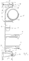
- Fig. 1 is a generally designated 1 support device for support represented by objects, each of which is used as a support and / or functional elements F provided shelves 2 and 3 on the support device 1 are supported.
- the carrying device 1 is U-shaped Support column 4 provided, each starting from a base leg 6 Legs 5 and 5 'for supporting the carrying device 1 in its installed position having.
- the support column 1 is in the embodiment according to the invention at its free ends U-leg 5.5 'by means of external journals 7 and 8 about a vertical axis 9 rotatably mounted.
- the respective upper and lower journals are 7.8 in Bearing assemblies 10,11 added, which in turn on an upper or lower plate part 12, 13 of a cabinet body 14 are supported.
- the shelves 2 and 3 on the base leg 6 firmly supported. It is also conceivable that the parts 2.3 around the The central axis M of the base leg 6 can be rotated (not shown).
- the support column 4 each composed of several parts, for example a welded connection between the base legs 6 and the two Legs 5.5 'can be provided.
- the support column 4 ' is formed as a one-piece molded part, which consists of a Pipe part is bent.
- 6 is a square molded part provided as the support column 4 with end legs 5.5 '. The Machining and adaptation of the square molding to the shelves 2,3 particularly easy.
- FIG. 1 when viewed in conjunction with FIG. 2, illustrates the Formation of the support device 1 in the region of the lower bearing 8 with a Brake 16, which is illustrated in more detail in the bottom view according to FIG. 5.
- the Brake 16 has one that is firmly connected to the bottom-side bearing assembly 11
- Counter member 17 with an elastic trough profile 18, in the a counter member 19 fixed on the underside of the leg 5 'as far as pivotable is that another turn (arrow D) is braked and thus the shelves 2 and 3 with this brake 16 in the to lock the barrier 14 optimal position are fixed (Fig. 1).
- To initiate a rotation D is the Braking resistor in the area of the trough profile 18 by a manual control easy to overcome, for example, on one of the functional elements F.
- the shelves 2 and 3 are for the cabinet body designed as a corner cabinet provided with a tendon-shaped section 20, the braked Position of the device 1 positioned opposite to a cabinet door 21 is that optimal accessibility and usability is achieved. It is also conceivable that the shelves 2,3 with a polygon Circumferential contour or a circular circumferential contour are dimensioned so that in the area of the cabinet door 21 the optimal rotation of the functional elements F is reached.
- FIG 3 and 4 illustrates that for access to the respective shelf 2,3 in the floor area B or B ' the pivoting or rotation of the support device 1 leads to a Partial area 22 'of the railing 22 in the area of the cabinet door 21 from the cabinet body 14 can be swung out, area B can be reached and then through Further movement or pivoting back the carrying device 1 as a whole can be shifted back into the rest position fixed by the brake 16.
- the shelves which have an essentially circular peripheral contour 2,3 are firmly supported on the support column 4, these being the shelves 2,3 eccentrically and thus the available usable area N (Fig. 4) is advantageously enlarged, the shelves 2, 3 have good accessibility and to the objects located on the shelves 2, 3 towards a view that improves their presentation. This is of interest, for example, when the cabinet door 21 is transparent Component consists of glass, for example.
- FIG. 5 is an additional, on the base leg 6 of the Support device 1 supported support plate 23 shown, this support plate 23 in particular as a stabilizing element for an existing wooden Insert shelf 24 is to be placed on the shelf 3 high weight loads to be able to record.
- the shelf 2 points in the illustrated Execution also a support plate 23 'on (Fig. 2).
- Fig. 2 On the support column 4 are 6 respective through holes in the region of the base leg 25,26 (Fig. 2) provided a variable height setting allow the shelves 2,3 by respective connecting elements (not visible). It is also conceivable for the shelves 2, 3 in the connection area to provide the base leg 6 with a clamping device by means of the shelves 2,3 by a stepless height adjustment (not shown) can be determined in largely variable installation positions.
- FIG. 6 is designed as a corner cabinet Cabinet body 14 provided with a cabinet opening 27 which by means of a Area of the support device 1 'supported cabinet door 21' is closable.
- This cabinet door 21 ' is rotated together with the carrying device 1' moved about the vertical axis 9 and can thus advantageously in the interior of the Cabinet body 14 are shifted.
- This is a front room for movement (Similar to Fig. 4) for this door 21 'unnecessary and the usable space in front of the Cabinet body 14 unaffected.
- the cabinet door 21 'by a parallel displacement be shifted towards the vertical axis 9 and for the backward shift is conceivable use a compression spring, not shown.
- the control of, for example on the support column 4 'fixed door 21' can advantageously have a curve control provided in the area of the bottom-side bearing assembly 11 34 (Fig. 6) can be reached, the guide cams 35 a respective opening or close position.
- FIG. 7 illustrates a third embodiment of the carrying device 1 ′′, the bearings 7, 8, the bearing assemblies 10, 11 of the support column 4 upper and a lower wall bracket 28, 29 pivotable on the wall W support, and thus the vertical axis 9 'is formed.
- the collar length L of the wall bracket 28, 29 is greater than the length S of the two free, arc-shaped extending U-leg 5.5 'of the support column 4. This ensures that the support device 1 "in the area of the as a mirror 30, cup holder 31 and shelves 32,33 trained support and functional elements F freely rotatable on the wall W is positioned.
- the functional elements 30 to 32 are fixed with the Support column 4 connected, it is also conceivable that here a pivotable Storage is provided or additional, customer-specific selectable Functional elements F to be fixed on the carrying device 1 ".
Landscapes
- Assembled Shelves (AREA)
- Supports Or Holders For Household Use (AREA)
- Warehouses Or Storage Devices (AREA)
Abstract
Description
- Fig. 1
- eine Perspektivdarstellung der erfindungsgemäßen Tragvorrichtung in einem Schrankkörper,
- Fig. 2
- eine Seitenansicht der Tragvorrichtung gemäß Fig. 1,
- Fig. 3
- eine Draufsicht auf die Tragvorrichtung gemäß Fig. 1,
- Fig. 4
- eine Draufsicht auf die Tragvorrichtung ähnlich Fig. 3 mit in Gebrauchsstellung verlagerten Tragelementen sowie geöffneter Schranktür,
- Fig. 5
- eine Unteransicht der im Schrankkörper befindlichen Tragvorrichtung,
- Fig. 6
- eine Perspektivdarstellung ähnlich Fig. 1 mit der Tragvorrichtung in einer zweiten Ausführungsform in einem Schrankkörper, und
- Fig. 7
- eine Seitenansicht der Tragvorrichtung in einer dritten Ausführungsform mit Wandhaltern.
Claims (15)
- Tragvorrichtung zur Abstützung von Gegenständen, mit einer U-förmigen, an den freien Enden der U-Schenkel (5,5') abgestützten Tragsäule (4), die an ihrem Basisschenkel (6) Trag- und/oder Funktionselemente (F) abstützt, dadurch gekennzeichnet, daß die Tragsäule (4) an ihren freien Enden der U-Schenkel (5,5') mittels außenseitiger Lagerzapfen (7,8) um eine Hochachse (9,9') drehbar gelagert ist.
- Tragvorrichtung nach Anspruch 1, dadurch gekennzeichnet, daß die Trag- oder Funktionselemente (F) am Basisschenkel (6) fest oder um die Mittelachse (M) des Basisschenkels (6) drehbar abgestützt sind.
- Tragvorrichtung nach Anspruch 1 oder 2, dadurch gekennzeichnet, daß die Tragsäule (4) als einstückiges Formteil ausgebildet ist.
- Tragvorrichtung nach Anspruch 1 oder 2, dadurch gekennzeichnet, daß die Tragsäule (4) aus mehreren Teilen zusammengesetzt ist.
- Tragvorrichtung nach einem der Ansprüche 1 bis 4, dadurch gekennzeichnet, daß die Lager (7,8) der Tragsäule (4) an einem oberen und unteren Wandhalter (28,29) abgestützt sind.
- Tragvorrichtung nach Anspruch 5, dadurch gekennzeichnet, daß die Kraglänge (L) der Wandhalter (28,29) größer ist als die Länge (S) der freien U-Schenkel (5,5') der Tragsäule (4).
- Tragvorrichtung nach einem der Ansprüche 1 bis 4, dadurch gekennzeichnet, daß die Lager (7,8) der Tragsäule (4) an einem oberen und unteren Plattenteil (12,13) eines Schrankkörpers (14;14') abgestützt sind.
- Tragvorrichtung nach Anspruch 7, dadurch gekennzeichnet, daß die Tragsäule (4) im Bereich zumindest eines der beiden Lager (7,8) mit einer Bremse (16) versehen ist.
- Tragvorrichtung nach Anspruch 7 oder 8, dadurch gekennzeichnet, daß an der Tragsäule (4) zumindest ein eine im wesentlichen kreisförmige Umfangskontur aufweisender Ablageboden (2,3) fest abgestützt ist.
- Tragvorrichtung nach Anspruch 9, dadurch gekennzeichnet, daß die Tragsäule (4) den Ablageboden (2,3) exzentrisch durchsetzt.
- Tragvorrichtung nach Anspruch 8, dadurch gekennzeichnet, daß ein für einen Eckschrank bestimmter Ablageboden (2,3) einen in Gegenüberlage zur Schranktür (21) positionierbaren sehnenförmigen Abschnitt (20) aufweist.
- Tragvorrichtung nach einem der Ansprüche 7 bis 10, dadurch gekennzeichnet, daß an der Tragsäule (4) und/oder einem oder mehreren der Tragelemente (F) eine in Öffnungs- bzw. Schließstellung vor eine Öffnung (27) eines Schrankkörpers (14') verschwenkbare Schranktür (21') abgestützt ist.
- Tragvorrichtung nach einem der Ansprüche 7 bis 12, dadurch gekennzeichnet, daß der Ablageboden (3) von einer am Basisschenkel (6) abgestützten Stützplatte (23) untergriffen ist.
- Tragvorrichtung nach einem der Ansprüche 7 bis 13, dadurch gekennzeichnet, daß am Basisschenkel (6) die Einbaulage für Ablageböden (2,3) im Schrankkörper (14;14') vorgebende Durchgangsbohrungen (25,26) für die Aufnahme von Verbindungselementen vorgesehen sind.
- Tragvorrichtung nach einem der Ansprüche 1 bis 13, dadurch gekennzeichnet, daß die Trag- und Funktionselemente (F) am Basisschenkel (6) der Tragsäule (4) stufenlos höhenverstellbar festgelegt sind.
Applications Claiming Priority (2)
| Application Number | Priority Date | Filing Date | Title |
|---|---|---|---|
| DE29919619U | 1999-11-08 | ||
| DE29919619U DE29919619U1 (de) | 1999-11-08 | 1999-11-08 | Tragvorrichtung zur Abstützung von Gegenständen |
Publications (2)
| Publication Number | Publication Date |
|---|---|
| EP1098130A1 true EP1098130A1 (de) | 2001-05-09 |
| EP1098130B1 EP1098130B1 (de) | 2006-06-07 |
Family
ID=8081336
Family Applications (1)
| Application Number | Title | Priority Date | Filing Date |
|---|---|---|---|
| EP20000123787 Expired - Lifetime EP1098130B1 (de) | 1999-11-08 | 2000-11-02 | Tragvorrichtung zur Abstützung von Gegenständen |
Country Status (2)
| Country | Link |
|---|---|
| EP (1) | EP1098130B1 (de) |
| DE (2) | DE29919619U1 (de) |
Cited By (1)
| Publication number | Priority date | Publication date | Assignee | Title |
|---|---|---|---|---|
| WO2012052113A1 (de) * | 2010-10-18 | 2012-04-26 | Kesseböhmer Holding OHG | Beschlag für möbel |
Families Citing this family (6)
| Publication number | Priority date | Publication date | Assignee | Title |
|---|---|---|---|---|
| DE29919619U1 (de) * | 1999-11-08 | 2000-01-05 | Heinrich J. Kesseböhmer KG, 49152 Bad Essen | Tragvorrichtung zur Abstützung von Gegenständen |
| DE20002313U1 (de) | 2000-02-10 | 2001-06-13 | Ninkaplast GmbH, 32108 Bad Salzuflen | Eckschranktürbeschlag |
| DE20010807U1 (de) * | 2000-06-17 | 2000-08-24 | Hetal-Werke Franz Hettich Gmbh & Co, 72275 Alpirsbach | Karussellvorrichtung für einen Eckschrank |
| FR2812177B1 (fr) * | 2000-07-26 | 2003-05-16 | Rennaise Du Meuble Soc | Meuble de rangement comportant un carrousel rotatif |
| DE202005005888U1 (de) | 2005-04-13 | 2006-08-17 | Heinrich J. Kesseböhmer KG | Eckschrank, insbesondere Kücheneckschrank |
| ATE525935T1 (de) | 2009-05-11 | 2011-10-15 | Vauth Sagel Holding Gmbh & Co | Drehbeschlag für einen eckschrank |
Citations (6)
| Publication number | Priority date | Publication date | Assignee | Title |
|---|---|---|---|---|
| DE3100819A1 (de) * | 1981-01-14 | 1982-07-29 | Drägerwerk AG, 2400 Lübeck | Deckendrehlager fuer die halterung von in ihrer lage feststellbaren medizinischen geraeten und der anschluesse von energie- und gasversorgungsleitungen im klinischen bereich |
| DE8811656U1 (de) | 1987-09-18 | 1988-10-27 | Rodet-Loisirs S.A., Saint Rambert d'Albon | Tragstange für Zubehörteile |
| US5279429A (en) * | 1990-01-22 | 1994-01-18 | Vauth-Sagel Gmbh & Co. | Pivoting tray with pivot bearing for corner cupboards |
| US5284255A (en) * | 1991-08-09 | 1994-02-08 | Hill-Rom Company, Inc. | Pivoted power column |
| DE29919619U1 (de) * | 1999-11-08 | 2000-01-05 | Heinrich J. Kesseböhmer KG, 49152 Bad Essen | Tragvorrichtung zur Abstützung von Gegenständen |
| DE20014540U1 (de) * | 2000-08-23 | 2000-10-19 | Heinrich J. Kesseböhmer KG, 49152 Bad Essen | Beschlag zur Abstützung einer Eckschranktür |
Family Cites Families (5)
| Publication number | Priority date | Publication date | Assignee | Title |
|---|---|---|---|---|
| DE3711535A1 (de) | 1987-04-06 | 1988-10-20 | Krause Robert Gmbh Co Kg | Karussellartige trageinrichtung, die in einen eckschrank od. dgl. einbaubar ist |
| DE9006119U1 (de) | 1990-05-30 | 1990-08-02 | Robert Krause GmbH & Co KG, 4992 Espelkamp | Eckschrankbeschlag, insbesondere für Küchenmöbel |
| DE4314350A1 (de) | 1993-04-30 | 1994-11-03 | Lido Duschabtrennung Prod | Duschabtrennung |
| DE4344658A1 (de) | 1993-12-24 | 1995-06-29 | Verena Heyden | Höhenverstellbarer Waschtisch |
| DE29605598U1 (de) | 1996-03-26 | 1996-07-04 | Hetal-Werke Franz Hettich Gmbh & Co, 72275 Alpirsbach | Fachboden eines Eckschranks, insbesondere Kücheneckschrank |
-
1999
- 1999-11-08 DE DE29919619U patent/DE29919619U1/de not_active Expired - Lifetime
-
2000
- 2000-11-02 EP EP20000123787 patent/EP1098130B1/de not_active Expired - Lifetime
- 2000-11-02 DE DE50012903T patent/DE50012903D1/de not_active Expired - Lifetime
Patent Citations (7)
| Publication number | Priority date | Publication date | Assignee | Title |
|---|---|---|---|---|
| DE3100819A1 (de) * | 1981-01-14 | 1982-07-29 | Drägerwerk AG, 2400 Lübeck | Deckendrehlager fuer die halterung von in ihrer lage feststellbaren medizinischen geraeten und der anschluesse von energie- und gasversorgungsleitungen im klinischen bereich |
| DE8811656U1 (de) | 1987-09-18 | 1988-10-27 | Rodet-Loisirs S.A., Saint Rambert d'Albon | Tragstange für Zubehörteile |
| FR2620780A1 (fr) * | 1987-09-18 | 1989-03-24 | Roddt Sa Ets H | Barre-support pour accessoires divers |
| US5279429A (en) * | 1990-01-22 | 1994-01-18 | Vauth-Sagel Gmbh & Co. | Pivoting tray with pivot bearing for corner cupboards |
| US5284255A (en) * | 1991-08-09 | 1994-02-08 | Hill-Rom Company, Inc. | Pivoted power column |
| DE29919619U1 (de) * | 1999-11-08 | 2000-01-05 | Heinrich J. Kesseböhmer KG, 49152 Bad Essen | Tragvorrichtung zur Abstützung von Gegenständen |
| DE20014540U1 (de) * | 2000-08-23 | 2000-10-19 | Heinrich J. Kesseböhmer KG, 49152 Bad Essen | Beschlag zur Abstützung einer Eckschranktür |
Cited By (3)
| Publication number | Priority date | Publication date | Assignee | Title |
|---|---|---|---|---|
| WO2012052113A1 (de) * | 2010-10-18 | 2012-04-26 | Kesseböhmer Holding OHG | Beschlag für möbel |
| US9103362B2 (en) | 2010-10-18 | 2015-08-11 | Kesseböhmer Holding e.K. | Fitting for furniture |
| RU2567225C2 (ru) * | 2010-10-18 | 2015-11-10 | Кессебёмер Холдинг Э.К. | Фурнитура для мебели |
Also Published As
| Publication number | Publication date |
|---|---|
| DE29919619U1 (de) | 2000-01-05 |
| DE50012903D1 (de) | 2006-07-20 |
| EP1098130B1 (de) | 2006-06-07 |
Similar Documents
| Publication | Publication Date | Title |
|---|---|---|
| DE4028452C2 (de) | ||
| DE10216769A1 (de) | Konsole für Tragböden in Haushaltsgeräten | |
| EP3854263B1 (de) | Armlehne, insbesondere für einen bürostuhl | |
| DE3744363C2 (de) | ||
| EP1098130A1 (de) | Tragvorrichtung zur Abstützung von Gegenständen | |
| DE69005604T2 (de) | Vorrichtung zum Lagern von geschirrartigen Behältern. | |
| EP2983553B1 (de) | Auszugsvorrichtung für schrankauszüge | |
| DE4237738A1 (de) | Wandstange für Brausen | |
| EP3358258B1 (de) | Möbel | |
| WO2009007304A1 (de) | Geschirrkorb mit klappbarer ablage | |
| EP1712153B1 (de) | Eckschrank, insbesondere Kücheneckschrank | |
| DE202013006958U1 (de) | Vorrichtung zur Warenpräsentation | |
| EP0024646B1 (de) | Strandkorb | |
| EP1704806B1 (de) | Toilettensitzerhöhungsvorrichtung | |
| EP3271537B1 (de) | Vorrichtung zur halterung von gegenständen | |
| DE3415850A1 (de) | Tragsockel fuer ein bildschirmgeraet z.b. ein fernsehgeraet | |
| WO2015121376A1 (de) | Regal zur präsentation von waren | |
| DE2434863A1 (de) | Moebelscharnier | |
| DE102004038059A1 (de) | Mittelkonsole mit einer höhenverstellbaren Armlehne | |
| DE3609381C2 (de) | Schwenkbeschlag | |
| DE9313364U1 (de) | Parallelogramm-Schwenkbeschlag, insbesondere für Fachböden von Küchenschränken | |
| DE20318368U1 (de) | Aufhängung eines Kabelkanals o.dgl. an einem Tischgestell und/oder an einer Tischplatte | |
| DE102006051181A1 (de) | Funktionselement sowie eine Einrichtung zu dessen Höhenverstellung | |
| DE19945839B4 (de) | Trägersystem für Warenträger | |
| DE10357331A1 (de) | Tragarm für Abstellgeräte |
Legal Events
| Date | Code | Title | Description |
|---|---|---|---|
| PUAI | Public reference made under article 153(3) epc to a published international application that has entered the european phase |
Free format text: ORIGINAL CODE: 0009012 |
|
| AK | Designated contracting states |
Kind code of ref document: A1 Designated state(s): DE |
|
| AX | Request for extension of the european patent |
Free format text: AL;LT;LV;MK;RO;SI |
|
| 17P | Request for examination filed |
Effective date: 20011102 |
|
| AKX | Designation fees paid |
Free format text: AT |
|
| RBV | Designated contracting states (corrected) |
Designated state(s): DE |
|
| REG | Reference to a national code |
Ref country code: DE Ref legal event code: 8566 |
|
| 17Q | First examination report despatched |
Effective date: 20041111 |
|
| GRAP | Despatch of communication of intention to grant a patent |
Free format text: ORIGINAL CODE: EPIDOSNIGR1 |
|
| GRAS | Grant fee paid |
Free format text: ORIGINAL CODE: EPIDOSNIGR3 |
|
| GRAA | (expected) grant |
Free format text: ORIGINAL CODE: 0009210 |
|
| AK | Designated contracting states |
Kind code of ref document: B1 Designated state(s): DE |
|
| REF | Corresponds to: |
Ref document number: 50012903 Country of ref document: DE Date of ref document: 20060720 Kind code of ref document: P |
|
| PLBE | No opposition filed within time limit |
Free format text: ORIGINAL CODE: 0009261 |
|
| STAA | Information on the status of an ep patent application or granted ep patent |
Free format text: STATUS: NO OPPOSITION FILED WITHIN TIME LIMIT |
|
| 26N | No opposition filed |
Effective date: 20070308 |
|
| REG | Reference to a national code |
Ref country code: DE Ref legal event code: R081 Ref document number: 50012903 Country of ref document: DE Owner name: KESSEBOEHMER HOLDING E.K., DE Free format text: FORMER OWNER: HEINRICH J. KESSEBOEHMER KG, 49152 BAD ESSEN, DE Effective date: 20120516 Ref country code: DE Ref legal event code: R082 Ref document number: 50012903 Country of ref document: DE Representative=s name: BUSSE & BUSSE PATENT- UND RECHTSANWAELTE PARTN, DE Effective date: 20120516 Ref country code: DE Ref legal event code: R081 Ref document number: 50012903 Country of ref document: DE Owner name: KESSEBOEHMER HOLDING KG, DE Free format text: FORMER OWNER: HEINRICH J. KESSEBOEHMER KG, 49152 BAD ESSEN, DE Effective date: 20120516 |
|
| REG | Reference to a national code |
Ref country code: DE Ref legal event code: R082 Ref document number: 50012903 Country of ref document: DE Representative=s name: BUSSE & BUSSE PATENT- UND RECHTSANWAELTE PARTN, DE Ref country code: DE Ref legal event code: R081 Ref document number: 50012903 Country of ref document: DE Owner name: KESSEBOEHMER HOLDING KG, DE Free format text: FORMER OWNER: KESSEBOEHMER HOLDING E.K., 49152 BAD ESSEN, DE |
|
| PGFP | Annual fee paid to national office [announced via postgrant information from national office to epo] |
Ref country code: DE Payment date: 20190822 Year of fee payment: 20 |
|
| REG | Reference to a national code |
Ref country code: DE Ref legal event code: R071 Ref document number: 50012903 Country of ref document: DE |