EP1098197A2 - Überwachung des Zustandes einer Flüssigkeit durch eine Öffnung - Google Patents
Überwachung des Zustandes einer Flüssigkeit durch eine Öffnung Download PDFInfo
- Publication number
- EP1098197A2 EP1098197A2 EP00123632A EP00123632A EP1098197A2 EP 1098197 A2 EP1098197 A2 EP 1098197A2 EP 00123632 A EP00123632 A EP 00123632A EP 00123632 A EP00123632 A EP 00123632A EP 1098197 A2 EP1098197 A2 EP 1098197A2
- Authority
- EP
- European Patent Office
- Prior art keywords
- fluid
- pair
- frequency
- conductors
- hertzian
- Prior art date
- Legal status (The legal status is an assumption and is not a legal conclusion. Google has not performed a legal analysis and makes no representation as to the accuracy of the status listed.)
- Withdrawn
Links
Images






Classifications
-
- G—PHYSICS
- G01—MEASURING; TESTING
- G01N—INVESTIGATING OR ANALYSING MATERIALS BY DETERMINING THEIR CHEMICAL OR PHYSICAL PROPERTIES
- G01N27/00—Investigating or analysing materials by the use of electric, electrochemical, or magnetic means
- G01N27/02—Investigating or analysing materials by the use of electric, electrochemical, or magnetic means by investigating impedance
- G01N27/04—Investigating or analysing materials by the use of electric, electrochemical, or magnetic means by investigating impedance by investigating resistance
- G01N27/06—Investigating or analysing materials by the use of electric, electrochemical, or magnetic means by investigating impedance by investigating resistance of a liquid
- G01N27/07—Construction of measuring vessels; Electrodes therefor
-
- G—PHYSICS
- G01—MEASURING; TESTING
- G01N—INVESTIGATING OR ANALYSING MATERIALS BY DETERMINING THEIR CHEMICAL OR PHYSICAL PROPERTIES
- G01N27/00—Investigating or analysing materials by the use of electric, electrochemical, or magnetic means
- G01N27/02—Investigating or analysing materials by the use of electric, electrochemical, or magnetic means by investigating impedance
-
- G—PHYSICS
- G01—MEASURING; TESTING
- G01N—INVESTIGATING OR ANALYSING MATERIALS BY DETERMINING THEIR CHEMICAL OR PHYSICAL PROPERTIES
- G01N33/00—Investigating or analysing materials by specific methods not covered by groups G01N1/00 - G01N31/00
- G01N33/26—Oils; Viscous liquids; Paints; Inks
- G01N33/28—Oils, i.e. hydrocarbon liquids
- G01N33/2888—Lubricating oil characteristics, e.g. deterioration
Definitions
- the present invention relates to devices for continuously electrically monitoring the condition of a fluid in a vessel such as the condition of oil for lubricating and particularly the condition of crankcase or sump oil in an internal combustion engine or the lubricant in a power transmission device.
- the device of the aforesaid Bauer, et al. application describes a sensor probe having spaced parallel plates or interdigitated strips of a generally rectangular configuration disposed to extend from a plug or closure in the wall of the vessel containing the fluid.
- the aforesaid Bauer, et al. device has the disadvantage of being bulky and somewhat cumbersome to install particularly in applications where the available access opening in the fluid vessel is small. Furthermore, the Bauer, et al. device has been found to be temperature dependant; and, it has been desired to achieve automatic temperature compensation or adjustment for the impedance measurements taken over the range of operating temperatures to which the fluid is exposed in service.
- the present invention provides a solution to the above-described problem of enabling continuous electrical monitoring in situ of the condition of fluid in a vessel such as engine crankcase or power transmission oil by electro-impedance spectroscopy techniques employing sensing of the changes in impedance by current measurement as an analog thereof between a pair of spaced parallel conductors at a first sub-Hertzian (low) and a second Hertzian (high) frequency.
- the impedance is computed from current measurements and the computed impedance adjusted for temperature variation and the difference in the impedance computed and the difference compared with stored values of impedance as a function of temperature for known fluid or lubricant conditions to determine the instant fluid conditions; and, an electrical indication is provided when a threshold condition has been reached.
- the sensor of the present invention has sensed changes of impedance difference of the fluid of over seven hundred percent (700%) from new to fully depleted fluid such as engine oil, which provides a high resolution sensitivity of measurement.
- the probe can be excited by a fractional or sub-Hertzian (low frequency alternating voltage and at a Hertzian (high) frequency and the phase shift of the resulting current at the high and low frequency determined by a zero crossing detector.
- the reactive impedance or reactance may then be computed and the differential reactance compared with known values to determine the fluid condition.
- the monitor of the present invention includes a sensor probe having the conductors comprising wires disposed or wound spirally, preferably helically, on an elongated mandrel near the distal end.
- the spirally wound configuration is sized and configured to be insertable through an existing dipstick hole in the engine or transmission.
- the proximal end of the mandrel extends outwardly of the existing dipstick aperture and has a relatively small casing or housing thereon which has disposed therein the electronic circuitry for impedance current measurement and the determination of the fluid condition from stored values of such measurements in a look-up table and providing an electrical indication signal upon the fluid reaching a critical threshold condition.
- the fluid condition monitor of the present invention is particularly suitable to automotive applications wherein the probe inserted into a dipstick aperture in the engine may be connected to the vehicle power supply for providing the electrical indication to a remote indicator provided on the instrument cluster for display to the vehicle operator.
- the spirally wound electrodes of the probe of the present invention are preferably wound in a particular pitch for an appropriate number of turns and then the pitch is reduced to about half for the remainder of turns to provide the desired length of the electrodes for the impedance measurement.
- the electrodes include lead means extending to the proximal end for connection to the circuitry externally of the dipstick aperture in the vessel containing the fluid to be monitored.
- the present invention thus provides a unique electrical monitor for insertion in an existing fluid dipstick aperture which permits retrofitting in field service by simply removing the manual dipstick and inserting a probe through the dipstick aperture and connecting the probe to a suitable power supply for energizing the circuitry provided on the probe.
- An RTD temperature sensor is included on the distal end of the probe for providing a temperature measurement of the fluid, which measurement is provided to the circuitry for providing a signal input for adjusting the impedance computed for measured current for temperature based on stored values or a known relationship established for variations in impedance of the electrodes in the fluid with temperature.
- the difference in the impedance computed at the fractional Hertzian (low) and Hertzian (high) frequencies is then computed and a comparison is made with the known values of impedance difference as a function of temperature for known fluid conditions.
- a pair of self-heated thermistors may be disposed in spaced relationship on the probe for detecting a fluid level below the desired threshold and providing a low-fluid defeat input for disabling the fluid condition impedance measurements and providing a low-fluid indication.
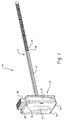
- the monitor of the present invention is indicated generally at 10 and includes a probe indicated generally at 12 comprising an elongated member or rod 14 preferably sized and configured for insertion into a dipstick aperture in a fluid vessel, such as an engine or power transmission, and includes a casing or housing indicated generally at 16 attached to the proximal end of the rod 14.
- Rod 14 has a plurality of spaced generally parallel electrodes 18, 20 disposed in spiral arrangement about the region adjacent the distal end of the rod 14.
- Casing 16 includes a shell 22 having a cover 24 secured thereto, as for example, by snap locking engagement in slots 26 provided in the cover.
- Shell 22 has an electrical receptacle 28 extending from one side thereof which is adapted for connection to a multiple pin wiring harness connector.
- probe 12 includes a spiral groove 30 formed thereon which has the electrodes 18,20 received therein for controlling the spacing or pitch of the spiral or helical arrangement of the electrodes.
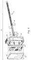
- rod 14 has a hollow 32 formed in the interior thereof and extending to the region of the distal end and has received therein a temperature sensing thermistor 34 which has a pair of electrical leads 36, 38 connected thereto and extending outwardly of the proximal end of the rod 14 for connection to the circuitry as will hereinafter be described.
- a pair of level sensing thermistors 40, 42 are received in the hollow 32 and located at suitable stations therealong so as to detect the presence of fluid thereon when the thermistors 40, 42 are self-heated in a manner known in the art.
- the thermistor 34 is exposed to the fluid in which the probe is to be immersed by a cut-out or aperture 44 provided in the rod 14; and, similarly thermistors 40, 42 are exposed to the fluid by cut-outs 46, 48.
- Thermistors 40, 42 also have electrical leads connected thereto and which extend outwardly of a proximal end of the rod 14 as denoted by reference numerals 50, 52, 54, 56 in FIG. 4.
- a pair of electrical leads 58, 60 are connected to the electrodes 18, 20 and extend outwardly from the proximal end of the probe 14.
- the arrangement of the electrodes 18, 20 are shown in the preferred practice wherein the electrodes have a constant pitch spacing denoted by the reference character "p" for an axial distance denoted by the reference character L 2 ; and, have an increased pitch or decreased pitch spacing denoted by the reference character "1/2p" for an axial distance denoted by the reference character L 1 .
- the portion of the spiral electrodes in the region L 2 provides improved sensitivity to the bulk impedance properties of the fluid at the Hertzian or higher frequencies; whereas, the portion of the electrode in the region denoted L 1 provides improved sensitivity to the surface effects of the fluid on the conductors as measured at the lower sub-Hertzian frequencies.
- a probe suitable for a dipstick application in an internal combustion engine has been satisfactorily made having a pitch diameter of about 0.25 inches (6.3 mm) formed of wire of about number 25 AWG (0.46 mm) diameter wire of non-magnetic material such as, for example, AISI type 303 stainless steel.
- the electrodes 18, 20 are spirally and preferably helically formed by winding over a rod 14 formed of suitable high dielectric material such as, for example polytetrafluoroethylene (PTFE) material.
- the electrodes are wound at a pitch spacing corresponding to the spacing "p" for the distance L 2 of about 4 inches (102 mm), with reference to FIG. 5, having about eight turns with a pitch spacing "p" of about 0.8 mm.
- the electrodes 18, 20 are wound for an additional length L 1 of about thirteen turns at a pitch spacing "1/2p" of about 28 mm for a distance L 1 of about 102 mm.
- L 1 the length of the wire diameter and pitch spacing and pitch diameter may be varied in accordance with the sensitivity, current carrying requirements and available space for winding for a particular application.
- the rod 14' has a generally ribbed, and preferably cruciform, configuration in transverse section for supporting the electrode wires 18', 20'.
- PTFE material has been found preferable, it will be understood that other materials may be used, as for example, polyphenylenesulfide or any other material stable in lubricating oil at temperatures up to about 150°C.
- FIG. 7 a block diagram of electrical system of the present invention 10 is illustrated wherein the detecting lead 60 from probe 14 is connected to the input of a current to voltage converter indicated generally at 62 which has its output on line 64 connected to the input of the system controller 66 which is of the type containing a microcomputer or a microprocessor.
- the remaining electrode lead 58 of probe 14 is connected to the excitation output of controller 66.
- the converter 62 as will be hereinafter described in greater detail converts the current through the probe electrodes, from a constant voltage excitation, to a voltage signal as an electrical analog of the probe impedance in the fluid.
- the probe electrodes may be excited from a constant current supply and the voltage measured as an analog of impedance change.
- the probe electrodes are excited with a relatively low constant voltage of about 250 milli-volts.
- the current to voltage converter has a gain control input along line 68 from the controller 66.
- the temperature sensing RTD 34 has its leads 36, 38 connected to a signal conditioning amplifier 70, which provides an input along line 72 to the controller 66.
- the RTD in the present practice provides a signal level of about 10 milli-volts per degree C.
- the optional level sensing thermistors 40, 42 have their leads 50, 54, 56 connected to a Wheatstone bridge circuit 74 which is connected via lines 76, 78 to the controller.
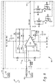
- a circuit schematic for the current to voltage converter 62 is illustrated wherein a sensitivity of 0.1 volt per nano ampere is determined by the resistor R1 in the feedback path from the output of IC1 with a secondary range providing a sensitivity of 0.01 volts per nano ampere through the resistor R2 and R3 upon closure of relay switch RY1.
- a sensitivity of 0.001 volts per nano ampere is obtained by closure of relay switch RY2 to include resistance R4 in the network.
- Transistors Q1 and Q2 are used to drive the relay coils of RY1 and RY2; and, the base junctions of Q1 and Q2 are driven by logic signals from the controller 66 to provide autoranging for measurement of a wide range, for example, three decades, of current sensing. Values and designations for the circuitry components are given in Table I.
- Device Type Device Type R1 100 MEG C1 0.1 ⁇ f R2 10 MEG C2 0.1 ⁇ f R3 1.1 MEG IC1 OPA128;A549 R4 1.1 MEG Q1 2N 6426 R5 50K Q2 2N 6426 R6 10K D1 1N 4003 R7 10K D2 1N4003 R8 10K D3 1N4003 R9 10K D4 1N4003 RY1 Relay Coil RY2 Relay Coil
- the controller 66 measures the current as an analog of the impedance of the electrodes 18,20 in the fluid at a first fractional or sub-Hertzian frequency and then at a frequency of at least one Hertz, and converts the current measurements to voltages.
- the measured currents are adjusted for temperature variation from a known relationship of electrode current as a function of temperature and a subtraction is performed and then the differential value is compared with values stored in a look-up table to determine whether the differential impedance is below a critical value established for a known fluid condition.
- the technique for performing this operation is shown and described in the aforesaid Patent Application Serial No. 09/220,556 filed December 23, 1998 incorporated herein and thus will not be described in further detail insofar as the electrical circuitry arrangement for performing these signal processing and data reduction functions.
- fluid level detection is performed by self-heating thermistors 40, 42 and determining the resistance change thereof due to the presence of liquid or the lack of change due to the absence of liquid in a manner well known in the art.
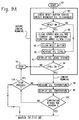
- step 84 makes a determination as to whether the Reset is on; and, if the answer is affirmative, the system proceeds to step 86 to clear the temperature function array and then proceeds to step 88 to clear the Reset button and proceeds to step 90 to measure the oil level with the energization of self-heating thermistors 40, 42. If however, the determination at step 84 is negative, the system proceeds directly to step 90 to measure the oil level.
- the system proceeds to display the oil level status at step 92 which is shown by an indicator 93 in the diagram of FIG. 7.
- step 94 the system proceeds to step 94 and makes a determination as to whether the oil level is satisfactory and if the determination is affirmative proceeds to step 96 to measure oil temperature. It will be understood that the mechanical system employing the fluid such as engine oil is activated by starting the engine prior to step 96. If the determination at step 94 is negative, the system proceeds to shut down at step 95.
- the system proceeds to display the measured oil temperature at step 98 by using temperature indicator 99 shown in FIG. 7.
- step 100 The system then proceeds to step 100 to make a determination as to whether the temperature is within a predetermined allowable range; and, if the determination at step 100 is affirmative the system proceeds to step 102 and applies the constant voltage excitation signal of about 250 milli-Volts to about 1 Volt RMS excitation to the probe electrodes 18, 20 sequentially at a Hertzian (high) frequency in the range of about 1-100 Hertz, preferably 1-10 Hertz and then at a fractional or sub-Hertzian (low) frequency in the range of about 10 to 50 milli-Hertz and preferably 40 to 50 milli-Hertz.
- a Hertzian (high) frequency in the range of about 1-100 Hertz, preferably 1-10 Hertz
- a fractional or sub-Hertzian (low) frequency in the range of about 10 to 50 milli-Hertz and preferably 40 to 50 milli-Hertz.
- step 100 determines if a Stop button has been energized; and, if not the system returns to step 96. If the operator has pressed the Stop button the system proceeds to step 95 to shut down.
- step 106 Upon the constant voltage excitation of the probe electrodes at step 102 sequentially at the two chosen frequencies, the system proceeds to step 106 and measures the current through the probe electrodes at each of the selected frequencies of excitation and proceeds to step 108 to store the measured currents (converted to voltage) and the average fluid temperature. The system then proceeds to step 110 and computes the impedance from the measured RMS currents I L , I H at the averaged temperature T F . The difference in the impedance ⁇ Z T is then computed at step 112.
- step 114 finds the fluid condition or RUL from a lookup table of the value of ⁇ Z T as a function of temperature for various levels of fluid condition or percentages of RUL.
- the lookup table may be compiled from the data points of the curves of FIG. 10
- Step 114 may be performed either by entering the graph of FIG. 10 at the ⁇ Z T from step 112 for the average temperature T F stored in step 108 and finding the fluid condition or RUL by interpolation; or, an equation may be fitted to the curves by any of the known curve fitting techniques such, as for example, multiple regression analysis.
- curve fitting techniques have been employed to the data in FIG. 10 provide the expressions for ⁇ Z T as follows:
- step 116 the system then proceeds to step 116 to make a determination as to whether the fluid condition or RUL computed in step 114 is less than a critical value; and, if the determination is positive, the system returns to step 104. However, if the system determination at step 116 is negative, the system proceeds to display a warning at step 118 which signals the condition indicator 119 in FIG. 7.
- the present invention thus provides a technique for determining the condition of a fluid such as, for example, engine oil on a running basis during engine operation, by computing values of impedance from current measurement taken with constant voltage excitation sequentially at Hertzian (high) and fractional Hertzian (low) frequencies and subtracting the temperature corrected values to determine a differential of the current (converted to voltage) as an analog of the change in impedance of the electrodes immersed in the fluid.
- the electrical analog of the differential of measured impedance at the two selected frequencies may then be compared with values of the impedance differentials as a function of temperature for known fluid conditions in a look-up table to determine whether the signal indicates a fluid condition less than a pre-selected or critical condition.
- the present invention computes the differential of impedances from the current measured at the sub-Hertzian (low) and Hertzian (high) frequencies
- the phase angle of the excitation voltage and the resultant current may be measured; and, the difference, or phase shift may be computed and compared with a table of known values as a function of temperature for various fluid conditions as an analog of reactive impedance change; and, is thus a means or way of determining the condition of the monitored fluid employing the technique of the present invention.
- values of the difference of the impedance ⁇ Z measured employing the technique of FIGS. 8 and 9 at the Hertzian and sub-Hertzian frequencies taken for samples of used passenger car motor oil (PCMO) are plotted as a function of the percent remaining useful life (RUL) of the oil in graphical form.
- the basis for end of remaining useful life is a known sample of oil provided by an engine oil manufacturer and designated by the oil manufacturer as at the "end of useful life" (EOL) based upon the oil manufacturers chemical analysis.
- the basis for 100% useful remaining life are the measurements taken from new engine oil of the same type. If these assumed boundary conditions are connected by a straight line plot, impedance measurements taken with the probe of the present invention may be entered on the straight line plot graph of FIG. 11 to determine the remaining useful life.
- FIG. 11 is based on impedance measurements performed in accordance with the present invention on SAE 5W-30 and SAE 10W-30 viscosity rated synthetic passenger car motor oil (PCMO).
- the in situ running impedance measurements taken in accordance with the present invention and utilizing the techniques shown and described herein may be used in real time to provide an indication of remaining useful life (RUL) which can be electrically displayed to the vehicle operator.
- the electrical indication may simply be provided when the oil condition has reached a predetermined critical state wherein the operator can be notified to change the engine oil before continuing operation.
- the spiral probe arrangement of the present invention shown in FIGS. 1 through 4 is particularly suitable for sizing and configuring so as to be insertable in an existing dipstick hole provided in an engine; and, thus the probe assembly of the present invention may be retrofitted on existing engines without any modification of the engine.
- the impedance Z measured in accordance with the technique of FIG. 9 for excitation at 250 milli-Volts are plotted as a function of frequency at frequencies of excitation current ranging from 1 milli-Hertz to 10 kHz for new and temperature aged synthetic PCMO measured with a spiral probe in accordance with FIGS. 1-4. From FIG. 12, it will be seen that after excitation at a first frequency of 10-100 Hertz and at a second frequency of from 10 to 50 milli-Hertz, the difference in impedance is quite sufficient to give the resolution needed to provide an indication of the change in fluid properties; and, thus the spiral probe of FIGS. 1 through 4 is considered to be a practical alternative to the parallel interdigitated electrode probe described in the aforesaid co-pending Bauer, et al. application serial number 09/220,556 for real time monitoring of engine oil.
- FIG. 13 an alternative technique for operating the system of FIG. 7 is illustrated in the form of a block flow diagram for the program of the microcomputer of FIG. 7. It will be understood that in the diagram of FIG. 13, those functions which are identical to those of FIG. 9 have been denoted with a similar reference numeral with a prime added.
- the alternative program of FIG. 13 causes the system of FIG. 7 to proceed from step 100' to step 120 wherein the output of at least one cycle of the one Volt RMS excitation signal at 0.040 Hertz and at least one cycle excitation of one Volt RMS at 1 Hertz is received by the microcontroller; and, the system proceeds to step 122 where the zero crossing of the current is detected; and, the zero crossing and average oil temperature both are stored at step 124.
- step 126 the phase angle shift ⁇ HI and ⁇ LO are computed from the stored zero crossings of step 122 and comparison with the zero crossing of the excitation voltage V 0 .
- step 128 values of the impedances Z HI , Z LO are computed from the measured currents I HI , I LO .
- step 130 the capacitive reactance Z iLO , Z iHI are computed from the phase angle shifts ⁇ LO , ⁇ HI respectively from step 126.
- step 132 calculates the change in capacitive reactive ⁇ Z i from the values of reactance computed in step 130.
- the system then proceeds to step 134 and finds, from a lookup table the values of ⁇ Z i versus temperature for various levels of fluid condition, the present condition or RUL of the fluid measured at the computed ⁇ Z i and measured temperature.
- the system then makes a determination at step 136 whether the fluid condition or RUL is less than a pre-selected critical level or RUL; and, if the result is affirmative, the system returns to step 104'. If the determination at step 136 is negative, the system proceeds to step 138 and provides a warning or display.
- values of ⁇ Z i in ohms are plotted as a function of oil temperature in degrees Centigrade for samples of 5W-30 synthetic motor oil as measured with a wire wound probe at 1 Volt RMS excitation at 10 Hertz and 100 milli-Hertz frequency for vehicles at different oil drain intervals.
- 100% RUL has been assigned to the upper curve for 100 mile drain oil; and, zero percent has been assigned to the lowest curve for 6300 mile drain oil.
- the values of fluid condition or RUL are found by interpolation from FIG. 14 by entering the graph at the temperature stored in step 122 and the value of ⁇ Z i computed in step 132 of the procedure of FIG. 13.
- the fluid condition or RUL for the temperature T stored at step 122 and ⁇ Z i computed at step 132 may be interpolated from values computed from the following expressions derived by curve fitting techniques to the graphs of FIG.
Landscapes
- Chemical & Material Sciences (AREA)
- Health & Medical Sciences (AREA)
- Life Sciences & Earth Sciences (AREA)
- General Health & Medical Sciences (AREA)
- Immunology (AREA)
- Pathology (AREA)
- Analytical Chemistry (AREA)
- Biochemistry (AREA)
- Chemical Kinetics & Catalysis (AREA)
- General Physics & Mathematics (AREA)
- Physics & Mathematics (AREA)
- Electrochemistry (AREA)
- Engineering & Computer Science (AREA)
- General Chemical & Material Sciences (AREA)
- Oil, Petroleum & Natural Gas (AREA)
- Food Science & Technology (AREA)
- Medicinal Chemistry (AREA)
- Investigating Or Analyzing Materials By The Use Of Electric Means (AREA)
- Lubrication Details And Ventilation Of Internal Combustion Engines (AREA)
Applications Claiming Priority (2)
| Application Number | Priority Date | Filing Date | Title |
|---|---|---|---|
| US09/433,495 US6377052B1 (en) | 1999-11-03 | 1999-11-03 | Monitoring fluid condition through an aperture |
| US433495 | 1999-11-03 |
Publications (2)
| Publication Number | Publication Date |
|---|---|
| EP1098197A2 true EP1098197A2 (de) | 2001-05-09 |
| EP1098197A3 EP1098197A3 (de) | 2001-06-27 |
Family
ID=23720335
Family Applications (1)
| Application Number | Title | Priority Date | Filing Date |
|---|---|---|---|
| EP00123632A Withdrawn EP1098197A3 (de) | 1999-11-03 | 2000-10-30 | Überwachung des Zustandes einer Flüssigkeit durch eine Öffnung |
Country Status (8)
| Country | Link |
|---|---|
| US (1) | US6377052B1 (de) |
| EP (1) | EP1098197A3 (de) |
| JP (1) | JP2001188054A (de) |
| KR (1) | KR20010060244A (de) |
| AU (1) | AU768050B2 (de) |
| BR (1) | BR0005348A (de) |
| CA (1) | CA2324843C (de) |
| MX (1) | MXPA00010816A (de) |
Cited By (18)
| Publication number | Priority date | Publication date | Assignee | Title |
|---|---|---|---|---|
| WO2003014729A1 (en) * | 2001-08-09 | 2003-02-20 | Commonwealth Scientific And Industrial Research Organisation | A method and apparatus for detecting extraneous matter in a fluid |
| WO2002065086A3 (fr) * | 2001-02-12 | 2003-09-25 | Totalfinaelf France | Methode et dispositif de mesure de l'efficacite d'une huile lubrifiante et leurs applications |
| WO2004031764A1 (en) * | 2002-09-30 | 2004-04-15 | University Of Dayton | Fluid condition monitor |
| WO2004036210A1 (en) * | 2002-10-16 | 2004-04-29 | The Lubrizol Corporation | Method for on-line monitoring of quality and condition of non-aqueous fluids |
| WO2004055525A1 (en) * | 2002-12-13 | 2004-07-01 | Eaton Corporation | Real-time monitoring of automatic transmission fluid condition |
| EP1515139A3 (de) * | 2003-09-15 | 2005-03-23 | Eaton Corporation | Methode zur Bestimmung des Flüssigkeitszustands von Dieselmotorschmiermitteln während des Betriebs in Echzeit |
| EP1798553A1 (de) * | 2005-12-17 | 2007-06-20 | ARGO-HYTOS GmbH | Verfahren und Sensorvorrichtung zur Überwachung der Qualität eines Schmier- oder Hydrauliköls |
| US7259575B2 (en) | 2005-04-08 | 2007-08-21 | The Lubrizol Corporation | Method for on-line fuel-dilution monitoring of engine lubricant |
| WO2008068484A1 (en) * | 2006-12-06 | 2008-06-12 | Abb Limited | Conductivity sensor |
| WO2011101099A1 (en) * | 2010-02-19 | 2011-08-25 | Services Petroliers Schlumberger | Fluid sensor and method of using same |
| WO2011101100A1 (en) * | 2010-02-19 | 2011-08-25 | Services Petroliers Schlumberger (Sps) | Fluid sensor and method of using same |
| GB2495132A (en) * | 2011-09-30 | 2013-04-03 | Zenith Oilfield Technology Ltd | Fluid mixture determination |
| CN103822648A (zh) * | 2014-03-14 | 2014-05-28 | 厦门易感智能测控技术有限公司 | 传感器 |
| US9541436B2 (en) | 2011-11-22 | 2017-01-10 | Lufkin Industries, Llc | Distributed two dimensional fluid sensor |
| US10107789B2 (en) | 2013-03-11 | 2018-10-23 | Zenith Oilfield Technology Limited | Multi-component fluid determination in a well bore |
| US10329898B2 (en) | 2010-11-19 | 2019-06-25 | Zenith Oilfield Technology Limited | High temperature downhole gauge system |
| EP3548718A4 (de) * | 2016-11-30 | 2020-12-16 | General Electric Company | Abtastsystem und -verfahren |
| RU234567U1 (ru) * | 2024-12-11 | 2025-06-02 | федеральное государственное автономное образовательное учреждение высшего образования "Национальный исследовательский ядерный университет МИФИ" (НИЯУ МИФИ) | Устройство для отбора проб моторного масла |
Families Citing this family (44)
| Publication number | Priority date | Publication date | Assignee | Title |
|---|---|---|---|---|
| EP1474676A4 (de) * | 2001-12-20 | 2005-03-09 | Prec Instr Corp | Online-ölzustandssensorsystem für dreh- und pendelmaschinen |
| US6891383B2 (en) * | 2003-08-27 | 2005-05-10 | Delphi Technologies, Inc. | Soot detector for engine oil |
| US6788072B2 (en) * | 2003-01-13 | 2004-09-07 | Delphi Technologies, Inc. | Apparatus and method for sensing particle accumulation in a medium |
| US6983223B2 (en) * | 2003-04-29 | 2006-01-03 | Watlow Electric Manufacturing Company | Detecting thermocouple failure using loop resistance |
| JP2007528356A (ja) * | 2003-04-30 | 2007-10-11 | ペプトロン カンパニー リミテッド | ペプチドが結合したビタミンc誘導体、その製造方法およびそれを含む組成物 |
| US20040240315A1 (en) * | 2003-06-02 | 2004-12-02 | Balan Prakash G. | Slotted draft tube mixing systems |
| US6839620B1 (en) | 2003-07-22 | 2005-01-04 | Eaton Corporation | Detecting soot during real time operation in diesel engine lubricant |
| US7043372B2 (en) * | 2003-11-26 | 2006-05-09 | Eaton Corporation | Fluid condition monitoring using broad spectrum impedance spectroscopy |
| US7049831B2 (en) * | 2004-02-16 | 2006-05-23 | Eaton Corporation | Fluid quality control using broad spectrum impedance spectroscopy |
| US6989680B2 (en) * | 2004-02-24 | 2006-01-24 | Eaton Corporation | Detection of coolant contamination in lubricating fluids |
| US7078910B2 (en) * | 2004-03-04 | 2006-07-18 | Eaton Corporation | Fluid formulation evaluation and improvement utilizing broad spectrum impedance spectroscopy |
| JP4260053B2 (ja) * | 2004-03-26 | 2009-04-30 | Ntn株式会社 | オイルチェックセンサ |
| WO2005114421A1 (en) * | 2004-05-03 | 2005-12-01 | Watlow Electric Manufacruring Company | Detecting thermocouple failure using loop resistance |
| US7509753B2 (en) * | 2004-06-30 | 2009-03-31 | Harley-Davidson Motor Company Group, Inc. | Apparatus for indicating oil temperature and oil level within an oil reservoir |
| KR100917947B1 (ko) * | 2004-07-07 | 2009-09-21 | 신토고교 가부시키가이샤 | 주물사의 수분치 측정용 전극 기구, 주물사의 수분치의 측정 장치, 주물사 혼련기로의 주수 방법 및 주수 장치 |
| JP4643243B2 (ja) * | 2004-12-13 | 2011-03-02 | Ntn株式会社 | オイルチェックセンサ |
| US8268629B2 (en) * | 2005-06-21 | 2012-09-18 | dTEC Systems L.L.C. | Method for the measurement of water and water-soluble components in non-aqueous liquids |
| US7621181B2 (en) * | 2006-04-12 | 2009-11-24 | Siemens Healthcare Diagnostics Inc. | Fluid level detector and analyzer |
| US20070289375A1 (en) * | 2006-06-14 | 2007-12-20 | Diba Industries, Inc. | Homogenous Fluid Level Sensing Devices |
| WO2008030585A1 (en) * | 2006-09-08 | 2008-03-13 | Rosemount Analytical, Inc. | Measuring conductivity of a liquid |
| US20080172187A1 (en) * | 2006-12-22 | 2008-07-17 | Paradigm Sensors, Llc | Impedance spectroscopy (is) methods and systems for characterizing fuel |
| WO2008101161A1 (en) * | 2007-02-15 | 2008-08-21 | Delphi Technologies, Inc. | Liquid properties sensor circuit |
| US20090112507A1 (en) * | 2007-10-29 | 2009-04-30 | Edney Daniel B | Fluid probe |
| US20090115434A1 (en) * | 2007-11-02 | 2009-05-07 | Hirthe Richard W | Sample Cell for Hand-Held Impedance Spectroscopy Device |
| US20090153149A1 (en) * | 2007-12-12 | 2009-06-18 | Norberto Hernandez | Obstructionless inline flex fuel sensor |
| US7800379B2 (en) * | 2007-12-12 | 2010-09-21 | Delphi Technologies, Inc. | Fuel sensor |
| KR200452575Y1 (ko) * | 2008-08-18 | 2011-03-07 | 주식회사 에스앤에스레볼루션 | 센서를 장착한 차량용 딥스틱 장치 |
| JP6346560B2 (ja) | 2011-05-26 | 2018-06-20 | ストーンリッジ・インコーポレッド | 煤センサシステム |
| US9488611B2 (en) | 2012-01-20 | 2016-11-08 | Rosemount Analytical Inc. | Low-conductivity contacting-type conductivity measurement |
| KR101292335B1 (ko) | 2013-01-28 | 2013-08-01 | (주) 해리아나 | 오일의 흐름 및 온도 측정기기 |
| US9354221B2 (en) | 2013-04-29 | 2016-05-31 | General Electric Company | Turbomachine lubricating oil analyzer system, computer program product and related methods |
| US9303540B2 (en) | 2013-04-29 | 2016-04-05 | General Electric Company | Turbomachine lubricating oil analyzer apparatus |
| US11090006B2 (en) | 2016-02-03 | 2021-08-17 | Cormetrics Llc | Modular sensing guidewire |
| JP6782098B2 (ja) * | 2016-05-27 | 2020-11-11 | Kyb株式会社 | 流体識別装置 |
| KR102074299B1 (ko) * | 2017-07-28 | 2020-03-02 | 주식회사 차후 | 유체 상태 측정 장치 |
| WO2019022339A1 (ko) * | 2017-07-28 | 2019-01-31 | 주식회사 차후 | 유체 상태 측정 장치 |
| DE102017223853A1 (de) * | 2017-12-28 | 2019-07-04 | Kautex Textron Gmbh & Co. Kg | Verfahren zum Bestimmen einer Qulitätseigenschaft einer Betriebsflüssigkeit in einem Betriebsflüssigkeitsbehälter für ein Kraftfahrzeug und Betriebsflüssigkeitsbehälter zum Durchführen des Verfahrens |
| EP3752799B1 (de) * | 2018-02-13 | 2025-04-02 | Renk America LLC | Messstab und elektronischer füllstandssensor |
| US10556102B1 (en) * | 2018-08-13 | 2020-02-11 | Biosense Webster (Israel) Ltd. | Automatic adjustment of electrode surface impedances in multi-electrode catheters |
| US10823700B2 (en) | 2019-02-15 | 2020-11-03 | Raytheon Technologies Corporation | Active oil debris monitor particle detection and monitoring system |
| US11536706B2 (en) | 2019-02-18 | 2022-12-27 | Raytheon Technologies Corporation | Active oil debris monitor phase angle calculation and monitoring system |
| US11137383B2 (en) | 2019-02-18 | 2021-10-05 | Raytheon Technologies Corporation | Active oil debris monitor particle detection and monitoring system |
| US11913897B2 (en) * | 2020-01-24 | 2024-02-27 | FluidInsight Ltd. | Fluid property sensor and fluid particle sensor |
| CN116429837B (zh) * | 2023-06-15 | 2023-09-08 | 可孚医疗科技股份有限公司 | 红细胞压积校正方法、系统及电化学测量系统 |
Family Cites Families (17)
| Publication number | Priority date | Publication date | Assignee | Title |
|---|---|---|---|---|
| GB1128970A (en) * | 1966-10-18 | 1968-10-02 | Hartmann & Braun Ag | An improved electrical conductivity cell |
| US3686926A (en) * | 1970-04-01 | 1972-08-29 | Boeing Co | Chip detecting and monitoring device |
| US3970925A (en) | 1974-05-10 | 1976-07-20 | Control Data Corporation | Direct reading reactance meter |
| US4165641A (en) | 1974-06-17 | 1979-08-28 | P. R. Mallory & Co. Inc. | Liquid level sensing means |
| JPS5885314A (ja) | 1981-11-17 | 1983-05-21 | Nissan Motor Co Ltd | エンジンオイルの劣化検知装置 |
| US4677847A (en) | 1985-09-30 | 1987-07-07 | Aisin Seiki Kabushiki Kaisha | Automotive engine oil monitoring system |
| US4757252A (en) | 1985-10-25 | 1988-07-12 | Drexelbrook Controls, Inc. | Probe system for measuring the condition of materials |
| US4733556A (en) | 1986-12-22 | 1988-03-29 | Ford Motor Company | Method and apparatus for sensing the condition of lubricating oil in an internal combustion engine |
| US5274335A (en) | 1992-04-06 | 1993-12-28 | General Motors Corporation | Oil sensor systems and methods of qualitatively determining oil type and condition |
| US5382942A (en) | 1993-07-06 | 1995-01-17 | Ford Motor Company | Engine oil monitoring system having an in-vehicle display of the current status of the oil |
| US5388448A (en) * | 1993-08-12 | 1995-02-14 | Vickers, Incorporated | Conductive particle detector |
| GB9515506D0 (en) | 1995-07-28 | 1995-09-27 | Collister Christopher J | Fluid permittivity measurement apparatus and method |
| US5852404A (en) * | 1996-07-30 | 1998-12-22 | Amini; Bijan K. | Apparatus for the detection and identification of metal particles, coolant or water in engine oil or hydraulic fluid |
| US5889200A (en) | 1996-08-30 | 1999-03-30 | The University Of Dayton | Tandem technique for fluid monitoring |
| NL1005421C2 (nl) | 1997-03-03 | 1998-09-18 | Meridian Instr Bv | Verbeterde inrichting voor het meten van de hoedanigheid van een fluïdum in een vat. |
| JP2001525059A (ja) | 1997-04-16 | 2001-12-04 | カイク・リミテッド | 液体組成の評価 |
| US6278281B1 (en) * | 1998-12-23 | 2001-08-21 | Eaton Corporation | Fluid condition monitor |
-
1999
- 1999-11-03 US US09/433,495 patent/US6377052B1/en not_active Expired - Fee Related
-
2000
- 2000-10-30 CA CA002324843A patent/CA2324843C/en not_active Expired - Fee Related
- 2000-10-30 JP JP2000330758A patent/JP2001188054A/ja active Pending
- 2000-10-30 EP EP00123632A patent/EP1098197A3/de not_active Withdrawn
- 2000-10-31 AU AU69640/00A patent/AU768050B2/en not_active Ceased
- 2000-11-01 BR BR0005348-1A patent/BR0005348A/pt not_active IP Right Cessation
- 2000-11-02 KR KR1020000065016A patent/KR20010060244A/ko not_active Ceased
- 2000-11-03 MX MXPA00010816A patent/MXPA00010816A/es active IP Right Grant
Cited By (30)
| Publication number | Priority date | Publication date | Assignee | Title |
|---|---|---|---|---|
| WO2002065086A3 (fr) * | 2001-02-12 | 2003-09-25 | Totalfinaelf France | Methode et dispositif de mesure de l'efficacite d'une huile lubrifiante et leurs applications |
| US7106075B2 (en) | 2001-08-09 | 2006-09-12 | Shenggen Hu | Online fluid contaminant detector |
| WO2003014729A1 (en) * | 2001-08-09 | 2003-02-20 | Commonwealth Scientific And Industrial Research Organisation | A method and apparatus for detecting extraneous matter in a fluid |
| AU2002319013B2 (en) * | 2001-08-09 | 2007-10-04 | Commonwealth Scientific And Industrial Research Organisation | A method and apparatus for detecting extraneous matter in a fluid |
| CN1301408C (zh) * | 2001-08-09 | 2007-02-21 | 联邦科学和工业研究组织 | 用于检测流体中杂质的方法和设备 |
| KR101014548B1 (ko) * | 2002-09-30 | 2011-02-16 | 유니버시티 오브 데이턴 | 유체 상태 모니터 |
| US7043967B2 (en) | 2002-09-30 | 2006-05-16 | University Of Dayton | Sensor device for monitoring the condition of a fluid and a method of using the same |
| CN100445742C (zh) * | 2002-09-30 | 2008-12-24 | 代顿大学 | 流体状态监测器 |
| WO2004031764A1 (en) * | 2002-09-30 | 2004-04-15 | University Of Dayton | Fluid condition monitor |
| WO2004036210A1 (en) * | 2002-10-16 | 2004-04-29 | The Lubrizol Corporation | Method for on-line monitoring of quality and condition of non-aqueous fluids |
| WO2004055525A1 (en) * | 2002-12-13 | 2004-07-01 | Eaton Corporation | Real-time monitoring of automatic transmission fluid condition |
| EP1515139A3 (de) * | 2003-09-15 | 2005-03-23 | Eaton Corporation | Methode zur Bestimmung des Flüssigkeitszustands von Dieselmotorschmiermitteln während des Betriebs in Echzeit |
| US7259575B2 (en) | 2005-04-08 | 2007-08-21 | The Lubrizol Corporation | Method for on-line fuel-dilution monitoring of engine lubricant |
| EP1798553A1 (de) * | 2005-12-17 | 2007-06-20 | ARGO-HYTOS GmbH | Verfahren und Sensorvorrichtung zur Überwachung der Qualität eines Schmier- oder Hydrauliköls |
| WO2008068484A1 (en) * | 2006-12-06 | 2008-06-12 | Abb Limited | Conductivity sensor |
| US9651511B2 (en) | 2006-12-06 | 2017-05-16 | Abb Limited | Conductivity sensor |
| US9086357B2 (en) | 2006-12-06 | 2015-07-21 | Abb Limited | Conductivity sensor |
| EP2385366A1 (de) * | 2010-02-19 | 2011-11-09 | Services Pétroliers Schlumberger | Flüssigkeitssensor und Verfahren zu dessen Verwendung |
| EP2362210A1 (de) * | 2010-02-19 | 2011-08-31 | Services Pétroliers Schlumberger | Flüssigkeitssensor und Verfahren zu dessen Verwendung |
| WO2011101100A1 (en) * | 2010-02-19 | 2011-08-25 | Services Petroliers Schlumberger (Sps) | Fluid sensor and method of using same |
| WO2011101099A1 (en) * | 2010-02-19 | 2011-08-25 | Services Petroliers Schlumberger | Fluid sensor and method of using same |
| US10329898B2 (en) | 2010-11-19 | 2019-06-25 | Zenith Oilfield Technology Limited | High temperature downhole gauge system |
| GB2495132A (en) * | 2011-09-30 | 2013-04-03 | Zenith Oilfield Technology Ltd | Fluid mixture determination |
| GB2495132B (en) * | 2011-09-30 | 2016-06-15 | Zenith Oilfield Tech Ltd | Fluid determination in a well bore |
| US9541665B2 (en) | 2011-09-30 | 2017-01-10 | Zenith Oilfield Technology Limited | Fluid determination in a well bore |
| US9541436B2 (en) | 2011-11-22 | 2017-01-10 | Lufkin Industries, Llc | Distributed two dimensional fluid sensor |
| US10107789B2 (en) | 2013-03-11 | 2018-10-23 | Zenith Oilfield Technology Limited | Multi-component fluid determination in a well bore |
| CN103822648A (zh) * | 2014-03-14 | 2014-05-28 | 厦门易感智能测控技术有限公司 | 传感器 |
| EP3548718A4 (de) * | 2016-11-30 | 2020-12-16 | General Electric Company | Abtastsystem und -verfahren |
| RU234567U1 (ru) * | 2024-12-11 | 2025-06-02 | федеральное государственное автономное образовательное учреждение высшего образования "Национальный исследовательский ядерный университет МИФИ" (НИЯУ МИФИ) | Устройство для отбора проб моторного масла |
Also Published As
| Publication number | Publication date |
|---|---|
| CA2324843C (en) | 2005-09-13 |
| JP2001188054A (ja) | 2001-07-10 |
| CA2324843A1 (en) | 2001-05-03 |
| KR20010060244A (ko) | 2001-07-06 |
| BR0005348A (pt) | 2001-12-26 |
| AU768050B2 (en) | 2003-11-27 |
| MXPA00010816A (es) | 2003-04-25 |
| AU6964000A (en) | 2001-05-10 |
| US6377052B1 (en) | 2002-04-23 |
| EP1098197A3 (de) | 2001-06-27 |
Similar Documents
| Publication | Publication Date | Title |
|---|---|---|
| US6377052B1 (en) | Monitoring fluid condition through an aperture | |
| EP1098196B1 (de) | Spiralförmige Elektrodenanordnung zur Überwachung des Zustandes einer Flüssigkeit | |
| EP1014082B1 (de) | Überwachung des Zustandes von einem Fluidum | |
| US4741204A (en) | Measurement of the depletion of basic additives in lubricating oil | |
| KR20040031025A (ko) | 저장기내 유체의 상태 및 레벨을 감지하는 방법 | |
| US6850865B2 (en) | Monitoring automatic transmission fluid condition in real time | |
| US20060196263A1 (en) | Fluid level sensor | |
| US5001927A (en) | Full sensing unit | |
| CN110470699B (zh) | 用于确定油的品质的方法和分析系统 | |
| JPH0333210B2 (de) | ||
| EP3702777B1 (de) | Pumpvorrichtung und verfahren zur bestimmung der konzentration einer substanz in einer flüssigkeit | |
| AU760233B2 (en) | Fluid condition monitor | |
| MXPA99011820A (en) | Flu condition monitor | |
| GB2286461A (en) | Boiling point determination |
Legal Events
| Date | Code | Title | Description |
|---|---|---|---|
| PUAI | Public reference made under article 153(3) epc to a published international application that has entered the european phase |
Free format text: ORIGINAL CODE: 0009012 |
|
| AK | Designated contracting states |
Kind code of ref document: A2 Designated state(s): AT BE CH CY DE DK ES FI FR GB GR IE IT LI LU MC NL PT SE |
|
| AX | Request for extension of the european patent |
Free format text: AL;LT;LV;MK;RO;SI |
|
| PUAL | Search report despatched |
Free format text: ORIGINAL CODE: 0009013 |
|
| AK | Designated contracting states |
Kind code of ref document: A3 Designated state(s): AT BE CH CY DE DK ES FI FR GB GR IE IT LI LU MC NL PT SE |
|
| AX | Request for extension of the european patent |
Free format text: AL;LT;LV;MK;RO;SI |
|
| RIC1 | Information provided on ipc code assigned before grant |
Free format text: 7G 01N 33/28 A, 7G 01N 27/02 B, 7G 01N 27/06 B, 7G 01N 27/22 B, 7G 01N 33/03 B |
|
| 17P | Request for examination filed |
Effective date: 20010922 |
|
| AKX | Designation fees paid |
Free format text: AT BE CH CY DE DK ES FI FR GB GR IE IT LI LU MC NL PT SE |
|
| STAA | Information on the status of an ep patent application or granted ep patent |
Free format text: STATUS: THE APPLICATION IS DEEMED TO BE WITHDRAWN |
|
| 18D | Application deemed to be withdrawn |
Effective date: 20070501 |