EP1098416B1 - Système de communication et de commande pour disjoncteur - Google Patents
Système de communication et de commande pour disjoncteur Download PDFInfo
- Publication number
- EP1098416B1 EP1098416B1 EP00203818.0A EP00203818A EP1098416B1 EP 1098416 B1 EP1098416 B1 EP 1098416B1 EP 00203818 A EP00203818 A EP 00203818A EP 1098416 B1 EP1098416 B1 EP 1098416B1
- Authority
- EP
- European Patent Office
- Prior art keywords
- circuit breaker
- communications
- application specific
- monitoring
- data processing
- Prior art date
- Legal status (The legal status is an assumption and is not a legal conclusion. Google has not performed a legal analysis and makes no representation as to the accuracy of the status listed.)
- Expired - Lifetime
Links
- 238000004891 communication Methods 0.000 title claims description 77
- 238000012544 monitoring process Methods 0.000 claims description 30
- 238000012545 processing Methods 0.000 claims description 19
- 238000011144 upstream manufacturing Methods 0.000 claims description 2
- 238000010586 diagram Methods 0.000 description 4
- 238000009826 distribution Methods 0.000 description 4
- 238000010438 heat treatment Methods 0.000 description 2
- 238000003466 welding Methods 0.000 description 2
- 230000003190 augmentative effect Effects 0.000 description 1
- 238000013461 design Methods 0.000 description 1
- 230000000694 effects Effects 0.000 description 1
- 238000005265 energy consumption Methods 0.000 description 1
- 239000000835 fiber Substances 0.000 description 1
- 238000009472 formulation Methods 0.000 description 1
- 239000004973 liquid crystal related substance Substances 0.000 description 1
- 238000004519 manufacturing process Methods 0.000 description 1
- 239000000463 material Substances 0.000 description 1
- 238000000034 method Methods 0.000 description 1
- 239000000203 mixture Substances 0.000 description 1
- 238000012986 modification Methods 0.000 description 1
- 230000004048 modification Effects 0.000 description 1
- 238000010248 power generation Methods 0.000 description 1
- 230000001681 protective effect Effects 0.000 description 1
- 239000007787 solid Substances 0.000 description 1
- 238000006467 substitution reaction Methods 0.000 description 1
Images


Classifications
-
- H—ELECTRICITY
- H02—GENERATION; CONVERSION OR DISTRIBUTION OF ELECTRIC POWER
- H02H—EMERGENCY PROTECTIVE CIRCUIT ARRANGEMENTS
- H02H3/00—Emergency protective circuit arrangements for automatic disconnection directly responsive to an undesired change from normal electric working condition with or without subsequent reconnection ; integrated protection
- H02H3/02—Details
- H02H3/04—Details with warning or supervision in addition to disconnection, e.g. for indicating that protective apparatus has functioned
-
- H—ELECTRICITY
- H02—GENERATION; CONVERSION OR DISTRIBUTION OF ELECTRIC POWER
- H02H—EMERGENCY PROTECTIVE CIRCUIT ARRANGEMENTS
- H02H1/00—Details of emergency protective circuit arrangements
- H02H1/0061—Details of emergency protective circuit arrangements concerning transmission of signals
Definitions
- the present invention relates generally to electric powered trip units, such as circuit breakers and more particularly to a communication and control system that cooperates with the electronic trip units.
- power is generated by a power generation company and supplied to a factory and thereafter distributed around the factory to various equipment such as, for example, motors, welding machinery, computers, heaters, lighting, and the like.
- Power distribution systems of this type are typically centrally located in switch gear rooms or substations. From there, power is divided up into branches such that each branch supplies power to a portion of the factory and/or specified loads. Frequently, transformers are disposed throughout the factory to step down the supply voltage to that required by specific pieces of equipment or portions of the factory. Therefore, a factory-power distribution system typically has a number of transformers servicing various types of equipment in various areas. Inherent with this, is the high cost of the power-distribution equipment such as transformers, as well as the cost of the equipment to which power is being supplied.
- circuit breakers when circuit breakers are utilized, they are used to detect more than just large overcurrent conditions caused by short circuit faults. In addition, they frequently detect lower level long-time overcurrent conditions and excessive ground currents.
- the simplest form of circuit breakers are thermally tripped as a result of heating caused by overcurrent conditions and, in this regard, are basically mechanical in nature. These mechanical-type breakers are incorporated into almost all circuit breakers, regardless of whether or not additional advanced circuitry is provided since they are extremely reliable over a long life cycle and provide a default trip-type level of protection.
- circuit breakers utilize electronic circuitry to monitor the level of current passing through the branch circuits and to trip the breaker when the current exceeds a pre-defined maximum value.
- Electronic circuit breakers are adjustable so as to fit a particular load or condition by the end user without designing or specifying different breakers.
- Breakers of this type typically include a microcontroller coupled to one or more current sensors. The microcontroller continuously monitors the digitized current values using a curve which defines permissible time frames in which both low-level and high-level overcurrent conditions may exist. If an overcurrent condition has maintained for longer than its permissible time frame, the breaker is tripped.
- Microcontrolled breakers may also include the ability to calculate root mean square (RMS) current values. This is necessary in order to prevent erroneously tripping a circuit breaker when a non-linear load, such as a welding machine, is coupled to the branch that it is protecting. The reason for this is that non-linear loads tend to produce harmonics in the current waveform. These harmonics tend to distort the current waveform, causing it to exhibit peak values which are augmented at the harmonic frequencies. When the microcontroller, which assumes that the current waveform is a sinusoidal current waveform, detects these peaks it may therefore trip the breaker even though the heating effect of the distorted waveform may not require that the circuit be broken.
- RMS root mean square
- microcontrollers in some circuit breakers are used to monitor and control or account for other types of faults, such as over or under voltage conditions and phase loss or imbalances.
- Such microcontrollers operate solenoids which are operatively connected to the trip mechanism of the circuit breaker. Therefore, while the thermal overload (mechanical) portion of the breaker will operate the trip mechanism, the solenoid will operate at the instruction of the microcontroller (or sometimes also at the instruction of external signals) to allow the trip mechanism to trip the associated circuit breaker.
- microcontrollers can provide when used in conjunction with circuit breakers, their use in circuit breakers is becoming more and more prevalent to the point of being standard.
- power may be typically provided in one of three ways or a combination thereof and would utilized either batteries, externally-supplied power, or power provided by potential transformers. Most users provide one power supply having battery back-up, for supplying all of the controllers for the entire substation or switch gear closet.
- MCCB Molded Case Circuit Breakers
- Such power components include, RMS and peak voltage, current and power, either by phase or in total and power factor related components.
- RMS peak voltage
- current and power either by phase or in total and power factor related components.
- Utilities and industrial customers are increasingly interested in performing end-use load studies. These studies are typically in the form of collecting interval power data so as to monitor and control energy consumption. While this is often done at a main load center, due to the increased costs and problems associated with time of use power consumption, such monitoring is being done closer to the individual end-use loads (i.e., motors, etc.). In this fashion, industrial customers are given a financial incentive to curtail power consumption when the cost of power is high as well as being able to more carefully and cost-effectively manage their power consumption by knowing where in their plant significant amounts of energy are being used.
- a discrete energy transducer When power monitoring is to be done, a discrete energy transducer is installed on the equipment or circuit to be monitored. This transducer generates a digital pulse output via a mechanical or solid state relay with the frequency of the pulse output being proportional to the magnitude of the measured quantity. This digital pulse output is either hard wired or communicated via power line-carrier system to a discrete pulse data recording device where it is time stamped.
- a centralized system providing communications to and from the circuit breakers.
- a communication system providing reconfigurability of the circuit breakers from a centralized location.
- monitoring of circuit breakers at a centralized location there is a need for a circuit breaker system that can communicate with a central system, the central system providing monitoring, communication and control functions from a central location to the circuit breaker system.
- Smart circuit breakers being controlled through a field-bus such as Profibus or CAN-bus, are described in document EP0824231 , which is considered to represent the closest prior art.
- the information system includes a circuit breaker connectable to a load and having a current interrupting portion.
- the information system also includes a data processing unit and a communications bus configured to be coupled to the data processing unit.
- the information system further includes an electronic monitoring unit, configured to provide at least one of monitoring, control, and communications functions for the circuit breaker and the electronic monitoring unit in communication with the circuit breaker and with the communications bus.
- Another embodiment of the present invention relates to a circuit breaker communications, monitoring, and control system.
- the circuit breaker communications, monitoring, and control system includes a central data processing unit and a communications bus coupled to the central data processing unit.
- the system also includes an application specific module coupled to the communications bus and a circuit breaker connectable to a load and having a current interrupting portion, and the circuit breaker coupled to the application specific module and communicating electronic signals with the application specific module.
- Still another embodiment of the invention relates to a circuit breaker system configured for use in a commercial environment.
- the circuit breaker system includes a circuit breaker connectable to a load and having a current interrupting portion.
- the system also includes a data processing means and a communications bus configured to be coupled to the data processing means.
- the system further includes an interfacing means, configured to provide at least one of monitoring, control, and communications functions for the circuit breaker and the electronic monitoring unit in communication with the circuit breaker and with the communications bus.
- System 10 includes a central computer 20 which may be any type of centralized data processing unit including, but not limited to a personal computer, a work station, a computer server, or a dedicated data processing device.
- Central computer 20 is coupled to a communications bus 30.
- Communications bus 30 may be any of a wide array of standard communications bus architectures including, but not limited to Ethernet, RS-485, fiber optic architectures, or other applicable bus architectures.
- Communications bus 30 may use any of a number of applicable communications protocols including, but not limited to profibus, profibus DP, TCP/IP, or any other applicable communications protocol.
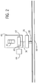
- Communications bus 30 is coupled to and in communication with a plurality of application specific modules 35 which are interfacing devices between communications bus 30 and a circuit breaker 40.
- Circuit breaker 40 is coupled to a load such as motors 45.
- circuit breaker 40 may be a Molded Case Circuit Breaker (MCCB), but alternatively circuit breaker 40 may be other types of circuit breakers.
- Circuit breaker 40 may be coupled to any of a variety of load types including, but not limited to, motors 45, welders, computers, heaters, lights, or any other type of electrical equipment.
- Circuit breaker 40 is configured to interrupt current flow to motor 45 or any applicable load when any of a variety of overload conditions are detected. Circuit breaker 40 may be tripped either by a short circuit condition, or by electronically sensing an overload condition, the overload condition being preprogrammed into the circuit breaker electronics. Trip types may include, but are not limited to, overload trips, short time trips, ground fault trips, and instantaneous trips.
- circuit breaker 40 is depicted as having a circuit breaker handle 41 for manual tripping or resetting of circuit breaker 40.
- circuit breaker 40 has an electronic trip unit 42, which in a preferred embodiment includes a liquid crystal display (LCD) readout or may include any type of display.
- Electronic trip unit 42 may be programmed to cause current interruption when any of a variety of overload conditions is sensed by the electronic trip unit.
- electronic trip unit 42 may be programmed to interrupt current when a specified root means square (RMS) current value is reached. Further, other types of overload conditions may be specified.
- RMS root means square
- electronic trip unit 42 includes an interface 43 for a communications adapter 44.
- Communications adapter 44 may be coupled to a personal computer, or other data processing device or further may be coupled to any of a variety of communications buses or communication devices.
- Communications adapter 44 allows an attached communications or data processing device to download information from electronic trip unit 42 or alternatively allows communication with electronic trip unit 42 to program electronic trip unit 42 for any of a variety of internal settings.
- Interface 43 between electronic trip unit 42 and communications adapter 44 may be any of a variety of serial output/serial input (SO/SI), serial input/serial output (SI/SO) communications lines 43, as depicted in FIG. 3 .
- communications adapter 44 preferably uses a serial interface 52, such as serial interface RS-232C as depicted in FIG. 3 .
- Serial interface 52 are not limited to serial interfaces of the type shown.
- Interfaces 43 and 52 may be any of a variety of applicable communications interfaces including Ethernet, parallel interfaces, or any other applicable interfaces.
- communications line 36 may be a three meter cable which is a serial communications interface as depicted in FIG. 3 .
- Serial communications interface 36 may include a plurality of communications lines such as serial input/serial output (SI/SO) line, serial output/serial input (SO/SI) line, serial clock (SCK) line and auxiliary power and signals line 37.
- SI/SO serial input/serial output
- SO/SI serial output/serial input
- SCK serial clock
- auxiliary power and signals line 37 is configured to carry power from ASM 35 to electronic trip unit 42.
- serial communication interface 36 is coupled to a monitoring, control, and communication processor 38 of ASM 35.
- the monitoring, control, and communication processor 38 carries out monitoring, control, and communication functions for ASM 35.
- the functions include communicating information to and from electronic trip unit 42, transmitting and receiving data from electronic trip unit 42, including information such as, but not limited to, the type of trip encountered, the time of trip, the current values at time of trip, (for example, a trip log).
- monitoring, control, and communications processor 38 may provide programming information to electronic trip unit 42, such as resetting trip values for electronic trip unit 42 and further may be used to receive real-time data from electronic trip unit 42.
- Monitoring, control, and communication processor 38 is coupled to a communications module 39 of ASM 35 which may be, in a preferred embodiment, a profibus communications IC SPC-3 communications device and required support electronics.
- ASM 35 is coupled to a communications bus 30, such as the RS-485 communications bus depicted in FIG. 3 .
- electronic trip unit 42 receives external power through a power line 50 that is coupled to ASM 35.
- ASM 35 supplies power to electronic trip unit 42 through line 37 depicted in FIG. 3 .
- Power line 50 may also supply zone select interlock signals to ASM 35.
- Power line 50 further powers ASM 35 ( FIG. 2 ).
- ASM 35 is powered by a 24 volt line 50.
- a zone selective interlock signal communicated along line 50 allows breakers that are downstream from a particular breaker to be tripped without tripping upstream breakers. This functionality allows an overload condition to be sensed and interrupted without interruption of the entire system. (For example, in an industrial setting it would not be desirable to shut down an entire factory system because a single load device fails thereby tripping a single circuit breaker.)
- Circuit breakers of the type commonly associated with circuit breaker 40 are typically low voltage circuit breakers in the range of 600 volts or less, but the communication and control system discussed above may be configured to operate with circuit breakers of any rated voltage. Further, circuit breakers commonly associated with circuit breakers 40 have current ratings from approximately 63 amps up to 1600 amps, however, other rated currents may also be applied. Further, circuit breakers of the type commonly associated with circuit breaker 40 are three phase circuit breakers which may be three pole or two pole circuit breakers however single phase circuit breakers may also be used.
Landscapes
- Remote Monitoring And Control Of Power-Distribution Networks (AREA)
Claims (10)
- Système (10) d'information, comprenant :un disjoncteur (40) pouvant être relié à une charge et comportant une partie d'interruption du courant ;une unité (20) de traitement de données ;un bus (30) de communication utilisant un protocole de communication Profibus et configuré en vue d'être couplé à l'unité (20) de traitement de données, etune unité (38) de surveillance électronique d'un module applicatif spécifique (35),étant entendu que l'unité (38) de surveillance électronique est configurée en vue d'assurer au moins l'une des fonctions de surveillance, de commande et de communication pour le disjoncteur (40) ;étant entendu que le module applicatif spécifique (35) est agencé entre le disjoncteur (40) et le bus (30) de communication, et communique avec le disjoncteur (40) et avec le bus (30) de communication, etétant entendu qu'une ligne (50) d'alimentation est reliée au module applicatif spécifique (35) et adaptée pour fournir au module applicatif spécifique (35) des signaux d'asservissement à sélectivité de zone de sorte à permettre de déclencher les disjoncteurs (40) qui sont en aval d'un disjoncteur (40) particulier, sans déclencher des disjoncteurs (40) en amont.
- Système (10) d'information selon la revendication 1 comprenant par ailleurs :une entrée de puissance couplée à l'unité (38) de surveillance électronique et capable de fournir de la puissance au disjoncteur (40).
- Système (10) d'information selon la revendication 1 comprenant par ailleurs :une interface (39) de communication couplée au disjoncteur (40).
- Système (10) d'information selon la revendication 3 comprenant par ailleurs :une unité de traitement de données couplée à l'interface (39) de communication.
- Système (10) d'information selon la revendication 1 dans lequel l'unité de traitement de données assure au moins l'une des fonctions de surveillance, de commande et de communication pour une pluralité de disjoncteurs (40).
- Système (10) de communication, de surveillance et de commande pour disjoncteur, consistant en un système (10) d'information selon l'une quelconque des revendications précédentes,
l'unité (20) de traitement de données étant une unité centrale de traitement de données ;
l'unité (38) de surveillance électronique étant un module applicatif spécifique (35), et
le disjoncteur (40) étant couplé au module applicatif spécifique (35) et communiquant par signaux électroniques avec le module applicatif spécifique (35). - Système (10) de communication, de surveillance et de commande pour disjoncteur selon la revendication 6 dans lequel le module applicatif spécifique communique un type de défaut à l'unité centrale (20) de traitement de données lorsque le disjoncteur (40) est déclenché.
- Système de communication, de surveillance et de commande pour disjoncteur selon la revendication 6 dans lequel le module applicatif spécifique (35) communique des données actuelles à l'unité centrale (20) de traitement de données.
- Système (10) de communication, de surveillance et de commande pour disjoncteur selon la revendication 6 dans lequel le module applicatif spécifique (35) communique un journal des déclenchements de disjoncteurs à l'unité centrale (20) de traitement de données.
- Système (10) de communication, de surveillance et de commande pour disjoncteur selon la revendication 6 dans lequel le module applicatif spécifique (35) fournit de la puissance au disjoncteur (40) lorsque le disjoncteur (40) est déclenché.
Applications Claiming Priority (2)
| Application Number | Priority Date | Filing Date | Title |
|---|---|---|---|
| US434348 | 1995-05-02 | ||
| US09/434,348 US6356422B1 (en) | 1999-11-05 | 1999-11-05 | Circuit breaker communication and control system |
Publications (3)
| Publication Number | Publication Date |
|---|---|
| EP1098416A2 EP1098416A2 (fr) | 2001-05-09 |
| EP1098416A3 EP1098416A3 (fr) | 2002-07-10 |
| EP1098416B1 true EP1098416B1 (fr) | 2018-04-25 |
Family
ID=23723861
Family Applications (1)
| Application Number | Title | Priority Date | Filing Date |
|---|---|---|---|
| EP00203818.0A Expired - Lifetime EP1098416B1 (fr) | 1999-11-05 | 2000-11-01 | Système de communication et de commande pour disjoncteur |
Country Status (2)
| Country | Link |
|---|---|
| US (1) | US6356422B1 (fr) |
| EP (1) | EP1098416B1 (fr) |
Families Citing this family (44)
| Publication number | Priority date | Publication date | Assignee | Title |
|---|---|---|---|---|
| US6760746B1 (en) | 1999-09-01 | 2004-07-06 | Eric Schneider | Method, product, and apparatus for processing a data request |
| USRE43690E1 (en) | 1999-03-22 | 2012-09-25 | Esdr Network Solutions Llc | Search engine request method, product, and apparatus |
| US7188138B1 (en) | 1999-03-22 | 2007-03-06 | Eric Schneider | Method, product, and apparatus for resource identifier registration and aftermarket services |
| US6338082B1 (en) | 1999-03-22 | 2002-01-08 | Eric Schneider | Method, product, and apparatus for requesting a network resource |
| US9141717B2 (en) | 1999-03-22 | 2015-09-22 | Esdr Network Solutions Llc | Methods, systems, products, and devices for processing DNS friendly identifiers |
| US8037168B2 (en) | 1999-07-15 | 2011-10-11 | Esdr Network Solutions Llc | Method, product, and apparatus for enhancing resolution services, registration services, and search services |
| USRE44207E1 (en) | 1999-09-01 | 2013-05-07 | Esdr Network Solutions Llc | Network resource access method, product, and apparatus |
| US6577963B1 (en) * | 2000-12-12 | 2003-06-10 | International Business Machines Corp. | Programmatic resetting of circuit breakers |
| US6612873B2 (en) * | 2000-12-20 | 2003-09-02 | Square D Company | Wiring adapter for connecting a remotely operable switching device to a control bus |
| US7136725B1 (en) | 2001-06-21 | 2006-11-14 | Paciorek Ronald R | Load shed notification method, product, and apparatus |
| GB0120748D0 (en) | 2001-08-25 | 2001-10-17 | Lucas Aerospace Power Equip | Generator |
| US20030048007A1 (en) * | 2001-09-07 | 2003-03-13 | Claude Mercier | Electronic power management system |
| US7532955B2 (en) * | 2002-02-25 | 2009-05-12 | General Electric Company | Distributed protection system for power distribution systems |
| US7111195B2 (en) * | 2002-02-25 | 2006-09-19 | General Electric Company | Method and system for external clock to obtain multiple synchronized redundant computers |
| AU2003217662A1 (en) | 2002-02-25 | 2003-09-09 | General Electric Company | Protection system for power distribution systems |
| US7058482B2 (en) | 2002-02-25 | 2006-06-06 | General Electric Company | Data sample and transmission modules for power distribution systems |
| US7747356B2 (en) * | 2002-02-25 | 2010-06-29 | General Electric Company | Integrated protection, monitoring, and control system |
| US20040036461A1 (en) * | 2002-08-22 | 2004-02-26 | Sutherland Peter Edward | Switchgear and relaying configuration |
| KR100655549B1 (ko) * | 2002-08-29 | 2006-12-07 | 엘지전자 주식회사 | 휴대 가능한 복합형 컴퓨터 |
| US7636616B2 (en) * | 2003-02-25 | 2009-12-22 | General Electric Company | Protection system for power distribution systems |
| US7039822B2 (en) * | 2003-02-27 | 2006-05-02 | Promos Technologies Inc. | Integrated circuit memory architecture with selectively offset data and address delays to minimize skew and provide synchronization of signals at the input/output section |
| US7515400B2 (en) * | 2003-02-28 | 2009-04-07 | Toyota Motor Sales, U.S.A., Inc. | Circuit breaker box and monitoring system |
| GB2401467B (en) * | 2003-05-09 | 2006-01-25 | Autoliv Dev | Improvements in or relating to a movable or removable unit for a motor vehicle |
| ATE379866T1 (de) * | 2003-07-30 | 2007-12-15 | Siemens Ag | Anschaltverfahren für einen blindleistungskompensator |
| US7696647B2 (en) * | 2003-09-15 | 2010-04-13 | Toshiba International Corp. | Coupling node |
| KR20060005923A (ko) * | 2004-07-14 | 2006-01-18 | 삼성전자주식회사 | 전자장치 |
| US7826932B2 (en) * | 2004-12-10 | 2010-11-02 | General Electric Company | Systems and methods for updating graphical representations on multiple interface devices |
| DE602006010123D1 (de) * | 2005-02-28 | 2009-12-17 | Delphi Tech Inc | Bremssystem mit einer fehlertoleranten Kommunikationsknoten-Architektur |
| CN100426612C (zh) * | 2005-03-24 | 2008-10-15 | 大全集团有限公司 | 内嵌web服务器的智能脱扣器 |
| US20110172840A1 (en) * | 2005-11-30 | 2011-07-14 | Radoslaw Narel | Centrally controlled protection system having reduced energy let-through mode |
| US7646575B2 (en) * | 2006-03-09 | 2010-01-12 | Utility Relay Co., Ltd. | Manually-controlled arc flash energy reduction system and method for circuit breaker trip units |
| US7294026B1 (en) * | 2006-07-20 | 2007-11-13 | Panduit Corp. | RS-485 connector plug and housing |
| US7570471B2 (en) * | 2007-02-20 | 2009-08-04 | Utility Relay Company | Circuit breaker trip unit with zone selective interlock and system monitoring |
| EP2383850B1 (fr) * | 2010-04-30 | 2017-08-09 | ABB Schweiz AG | Procédé de réalisation d'un entretien/d'une maintenance sur un tableau de commutation et tableau de commutation correspondant |
| CN102236687A (zh) * | 2010-05-04 | 2011-11-09 | 孙德名 | 断电保护装置 |
| US8385035B2 (en) | 2010-07-16 | 2013-02-26 | General Electric Company | Protection system having reduced energy let-through mode and zone selectivity |
| US8797720B2 (en) | 2011-09-13 | 2014-08-05 | Utility Relay Company | Manually-controlled arc flash energy reduction system and method for circuit breaker trip units |
| US9368955B2 (en) | 2013-02-14 | 2016-06-14 | General Electric Company | System and method to derive power and trip a circuit breaker from an external device |
| GB2530498A (en) * | 2014-09-23 | 2016-03-30 | Martin Bills | A diagnostic and communication device for circuit breakers |
| US9748763B2 (en) | 2014-11-04 | 2017-08-29 | General Electric Company | Circuit protection devices and methods of monitoring protection devices in a power distribution system |
| US9692224B2 (en) | 2015-06-15 | 2017-06-27 | General Electric Company | Power distribution systems and methods of monitoring zone selective interlocking in a power distribution system |
| US9618548B1 (en) | 2015-12-15 | 2017-04-11 | Schneider Electric USA, Inc. | Integrated systems for miniature circuit breaker load centers |
| CN107658836A (zh) * | 2017-09-27 | 2018-02-02 | 德力西电气有限公司 | 一种用于断路器的智能控制装置及断路器 |
| CN113241744B (zh) * | 2021-06-09 | 2023-05-02 | 中国南方电网有限责任公司超高压输电公司贵阳局 | 变电站中开关装置的控制回路 |
Citations (2)
| Publication number | Priority date | Publication date | Assignee | Title |
|---|---|---|---|---|
| EP0824231A1 (fr) * | 1996-08-13 | 1998-02-18 | Dürr Systems GmbH | Système de fabrication |
| EP1530104A2 (fr) * | 2003-10-25 | 2005-05-11 | ABB PATENT GmbH | Appareil de commande |
Family Cites Families (16)
| Publication number | Priority date | Publication date | Assignee | Title |
|---|---|---|---|---|
| US4631625A (en) | 1984-09-27 | 1986-12-23 | Siemens Energy & Automation, Inc. | Microprocessor controlled circuit breaker trip unit |
| FR2592737B1 (fr) | 1986-01-03 | 1988-03-18 | Merlin Gerin | Lecteur pour declencheur numerique associe a un appareil de coupure de courant |
| DE3609430A1 (de) * | 1986-03-20 | 1987-09-24 | Ruhrtal Gmbh | Verfahren zur chronologisch richtigen registrierung von informationsinhalten einer vielzahl von informationsquellen |
| AT393338B (de) * | 1986-07-29 | 1991-09-25 | Sprecher Energie Oesterreich | Einrichtung zur steuerung und ueberwachung einer elektrischen energieverteilungsanlage |
| DE3786908D1 (de) * | 1986-12-12 | 1993-09-09 | Siemens Ag | Schutzschaltsystem. |
| US4870531A (en) | 1988-08-15 | 1989-09-26 | General Electric Company | Circuit breaker with removable display and keypad |
| US4947126A (en) | 1989-04-04 | 1990-08-07 | Siemens Energy & Automation, Inc. | Ground fault current rectification and measuring circuit |
| US5239144A (en) | 1992-02-07 | 1993-08-24 | Siemens Energy & Automation, Inc. | Circuit breaker trip unit interlock |
| US5426592A (en) | 1992-03-06 | 1995-06-20 | Siemens Energy & Automation, Inc. | Circuit breaker trip unit which automatically adapts to operated with a particular display module |
| US5617286A (en) | 1994-09-30 | 1997-04-01 | Siemens Energy & Automation, Inc. | Circuit breaker having data recording |
| US5940257A (en) | 1995-09-29 | 1999-08-17 | Siemens Energy & Automation, Inc. | Method and apparatus for alternating current monitoring with phase and magnitude measurement |
| US5909368A (en) * | 1996-04-12 | 1999-06-01 | Fisher-Rosemount Systems, Inc. | Process control system using a process control strategy distributed among multiple control elements |
| US5907467A (en) | 1996-06-28 | 1999-05-25 | Siemens Energy & Automation, Inc. | Trip device for an electric powered trip unit |
| US5754386A (en) | 1996-06-28 | 1998-05-19 | Siemens Energy And Automation, Inc. | Trip device for an electric powered trip unit |
| US5740027A (en) | 1996-06-28 | 1998-04-14 | Siemens Energy & Automation, Inc. | Trip device for an electric powered trip unit |
| US5982596A (en) * | 1998-05-05 | 1999-11-09 | George Authur Spencer | Load center monitor and digitally enhanced circuit breaker system for monitoring electrical power lines |
-
1999
- 1999-11-05 US US09/434,348 patent/US6356422B1/en not_active Expired - Lifetime
-
2000
- 2000-11-01 EP EP00203818.0A patent/EP1098416B1/fr not_active Expired - Lifetime
Patent Citations (2)
| Publication number | Priority date | Publication date | Assignee | Title |
|---|---|---|---|---|
| EP0824231A1 (fr) * | 1996-08-13 | 1998-02-18 | Dürr Systems GmbH | Système de fabrication |
| EP1530104A2 (fr) * | 2003-10-25 | 2005-05-11 | ABB PATENT GmbH | Appareil de commande |
Also Published As
| Publication number | Publication date |
|---|---|
| EP1098416A2 (fr) | 2001-05-09 |
| US6356422B1 (en) | 2002-03-12 |
| EP1098416A3 (fr) | 2002-07-10 |
Similar Documents
| Publication | Publication Date | Title |
|---|---|---|
| EP1098416B1 (fr) | Système de communication et de commande pour disjoncteur | |
| US6297939B1 (en) | Zone selective interlock for a circuit breaker system | |
| US7132951B2 (en) | Apparatus and method for protecting an uninterruptible power supply and critical loads connected thereto | |
| CN101194217B (zh) | 使用固态功率控制器的配电系统 | |
| EP2218087B1 (fr) | Relais de protection et son interface homme-machine | |
| CN102124620B (zh) | 配置独立自供电数字控制继电器的方法 | |
| US6661632B2 (en) | Data acquisition system for a circuit breaker | |
| JP5809797B2 (ja) | 電力を切り替えるための方法及び装置 | |
| US20130035800A1 (en) | Method and system for power management in substations | |
| KR101223670B1 (ko) | 상용-비상용 전력수급 제어 기능을 가지는 전력컨트롤러가 내장된 수배전반 및 이의 작동방법 | |
| US11664664B2 (en) | Method and apparatus for preventing same building solar panel produced voltage spikes on a neighbor's electric utility service | |
| CN211296159U (zh) | 一种超负荷控制电路 | |
| KR101902169B1 (ko) | 전원 공급 계통의 전력 설비 소손 감시 및 고장 예방 제어 장치와 그 제어 방법 | |
| WO2021101884A1 (fr) | Système de gestion de surcharge de puissance pour centres de données de réseau | |
| CN103580007A (zh) | 一种智能框架控制器 | |
| CN121263937A (zh) | 用于配电板的保护架构 | |
| CN101783498A (zh) | 模块化微机电动机保护监控装置 | |
| KR101473224B1 (ko) | 블랙아웃 및 아크결함 방지용 세대분전반 | |
| CN219554656U (zh) | 一种检修电源配电优化设备 | |
| KR100653284B1 (ko) | 3상 디지털 유피에스 시스템 | |
| CN220440369U (zh) | 一种户内线路保护装置 | |
| JP2005020945A (ja) | 所内電力監視制御システム | |
| Grebe | Power quality and the utility/customer interface | |
| RU2463693C2 (ru) | Автономное самозапитывающееся реле с числовым управлением | |
| WO2022180350A1 (fr) | Système de correction de facteur de puissance |
Legal Events
| Date | Code | Title | Description |
|---|---|---|---|
| PUAI | Public reference made under article 153(3) epc to a published international application that has entered the european phase |
Free format text: ORIGINAL CODE: 0009012 |
|
| AK | Designated contracting states |
Kind code of ref document: A2 Designated state(s): AT BE CH CY DE DK ES FI FR GB GR IE IT LI LU MC NL PT SE TR |
|
| AX | Request for extension of the european patent |
Free format text: AL;LT;LV;MK;RO;SI |
|
| PUAL | Search report despatched |
Free format text: ORIGINAL CODE: 0009013 |
|
| AK | Designated contracting states |
Kind code of ref document: A3 Designated state(s): AT BE CH CY DE DK ES FI FR GB GR IE IT LI LU MC NL PT SE TR |
|
| AX | Request for extension of the european patent |
Free format text: AL;LT;LV;MK;RO;SI |
|
| 17P | Request for examination filed |
Effective date: 20030110 |
|
| AKX | Designation fees paid |
Designated state(s): DE ES FR GB IT |
|
| 17Q | First examination report despatched |
Effective date: 20080721 |
|
| RAP1 | Party data changed (applicant data changed or rights of an application transferred) |
Owner name: SIEMENS INDUSTRY, INC. |
|
| REG | Reference to a national code |
Ref country code: DE Ref legal event code: R079 Ref document number: 60049810 Country of ref document: DE Free format text: PREVIOUS MAIN CLASS: H02H0003040000 Ipc: H02H0001000000 |
|
| RIC1 | Information provided on ipc code assigned before grant |
Ipc: H02H 1/00 20060101AFI20160621BHEP Ipc: H02H 3/04 20060101ALI20160621BHEP |
|
| RAP1 | Party data changed (applicant data changed or rights of an application transferred) |
Owner name: SIEMENS INDUSTRY, INC. |
|
| GRAP | Despatch of communication of intention to grant a patent |
Free format text: ORIGINAL CODE: EPIDOSNIGR1 |
|
| STAA | Information on the status of an ep patent application or granted ep patent |
Free format text: STATUS: GRANT OF PATENT IS INTENDED |
|
| GRAJ | Information related to disapproval of communication of intention to grant by the applicant or resumption of examination proceedings by the epo deleted |
Free format text: ORIGINAL CODE: EPIDOSDIGR1 |
|
| STAA | Information on the status of an ep patent application or granted ep patent |
Free format text: STATUS: EXAMINATION IS IN PROGRESS |
|
| INTG | Intention to grant announced |
Effective date: 20171017 |
|
| INTC | Intention to grant announced (deleted) | ||
| GRAP | Despatch of communication of intention to grant a patent |
Free format text: ORIGINAL CODE: EPIDOSNIGR1 |
|
| STAA | Information on the status of an ep patent application or granted ep patent |
Free format text: STATUS: GRANT OF PATENT IS INTENDED |
|
| INTG | Intention to grant announced |
Effective date: 20180111 |
|
| GRAA | (expected) grant |
Free format text: ORIGINAL CODE: 0009210 |
|
| GRAS | Grant fee paid |
Free format text: ORIGINAL CODE: EPIDOSNIGR3 |
|
| STAA | Information on the status of an ep patent application or granted ep patent |
Free format text: STATUS: THE PATENT HAS BEEN GRANTED |
|
| AK | Designated contracting states |
Kind code of ref document: B1 Designated state(s): DE ES FR GB IT |
|
| REG | Reference to a national code |
Ref country code: GB Ref legal event code: FG4D |
|
| REG | Reference to a national code |
Ref country code: DE Ref legal event code: R096 Ref document number: 60049810 Country of ref document: DE |
|
| PG25 | Lapsed in a contracting state [announced via postgrant information from national office to epo] |
Ref country code: ES Free format text: LAPSE BECAUSE OF FAILURE TO SUBMIT A TRANSLATION OF THE DESCRIPTION OR TO PAY THE FEE WITHIN THE PRESCRIBED TIME-LIMIT Effective date: 20180425 |
|
| REG | Reference to a national code |
Ref country code: DE Ref legal event code: R097 Ref document number: 60049810 Country of ref document: DE |
|
| RIC2 | Information provided on ipc code assigned after grant |
Ipc: H02H 1/00 20060101AFI20160621BHEP Ipc: H02H 3/04 20060101ALI20160621BHEP |
|
| PG25 | Lapsed in a contracting state [announced via postgrant information from national office to epo] |
Ref country code: IT Free format text: LAPSE BECAUSE OF FAILURE TO SUBMIT A TRANSLATION OF THE DESCRIPTION OR TO PAY THE FEE WITHIN THE PRESCRIBED TIME-LIMIT Effective date: 20180425 |
|
| PLBE | No opposition filed within time limit |
Free format text: ORIGINAL CODE: 0009261 |
|
| STAA | Information on the status of an ep patent application or granted ep patent |
Free format text: STATUS: NO OPPOSITION FILED WITHIN TIME LIMIT |
|
| 26N | No opposition filed |
Effective date: 20190128 |
|
| REG | Reference to a national code |
Ref country code: DE Ref legal event code: R119 Ref document number: 60049810 Country of ref document: DE |
|
| GBPC | Gb: european patent ceased through non-payment of renewal fee |
Effective date: 20181101 |
|
| PG25 | Lapsed in a contracting state [announced via postgrant information from national office to epo] |
Ref country code: DE Free format text: LAPSE BECAUSE OF NON-PAYMENT OF DUE FEES Effective date: 20190601 Ref country code: FR Free format text: LAPSE BECAUSE OF NON-PAYMENT OF DUE FEES Effective date: 20181130 |
|
| PG25 | Lapsed in a contracting state [announced via postgrant information from national office to epo] |
Ref country code: GB Free format text: LAPSE BECAUSE OF NON-PAYMENT OF DUE FEES Effective date: 20181101 |