EP1530104A2 - Appareil de commande - Google Patents
Appareil de commande Download PDFInfo
- Publication number
- EP1530104A2 EP1530104A2 EP20040023530 EP04023530A EP1530104A2 EP 1530104 A2 EP1530104 A2 EP 1530104A2 EP 20040023530 EP20040023530 EP 20040023530 EP 04023530 A EP04023530 A EP 04023530A EP 1530104 A2 EP1530104 A2 EP 1530104A2
- Authority
- EP
- European Patent Office
- Prior art keywords
- control
- control unit
- interface
- communication
- network
- Prior art date
- Legal status (The legal status is an assumption and is not a legal conclusion. Google has not performed a legal analysis and makes no representation as to the accuracy of the status listed.)
- Withdrawn
Links
Images


Classifications
-
- G—PHYSICS
- G05—CONTROLLING; REGULATING
- G05B—CONTROL OR REGULATING SYSTEMS IN GENERAL; FUNCTIONAL ELEMENTS OF SUCH SYSTEMS; MONITORING OR TESTING ARRANGEMENTS FOR SUCH SYSTEMS OR ELEMENTS
- G05B19/00—Program-control systems
- G05B19/02—Program-control systems electric
- G05B19/04—Program control other than numerical control, i.e. in sequence controllers or logic controllers
- G05B19/042—Program control other than numerical control, i.e. in sequence controllers or logic controllers using digital processors
- G05B19/0423—Input/output
-
- G—PHYSICS
- G05—CONTROLLING; REGULATING
- G05B—CONTROL OR REGULATING SYSTEMS IN GENERAL; FUNCTIONAL ELEMENTS OF SUCH SYSTEMS; MONITORING OR TESTING ARRANGEMENTS FOR SUCH SYSTEMS OR ELEMENTS
- G05B2219/00—Program-control systems
- G05B2219/20—Pc systems
- G05B2219/25—Pc structure of the system
- G05B2219/25234—Direct communication between two modules instead of normal network
-
- H—ELECTRICITY
- H02—GENERATION; CONVERSION OR DISTRIBUTION OF ELECTRIC POWER
- H02H—EMERGENCY PROTECTIVE CIRCUIT ARRANGEMENTS
- H02H7/00—Emergency protective circuit arrangements specially adapted for specific types of electric machines or apparatus or for sectionalised protection of cable or line systems, and effecting automatic switching in the event of an undesired change from normal working conditions
- H02H7/26—Sectionalised protection of cable or line systems, e.g. for disconnecting a section on which a short-circuit, earth fault, or arc discharge has occured
Definitions
- the invention relates to a control device for controlling and monitoring of switching devices and / or consumers in a switchgear, in particular in a low-voltage switchgear.
- the invention further relates to a system for controlling and Monitoring of switching devices and / or consumers, which at least one has control unit according to the invention.
- a control device of the type mentioned which is a programmable logic Control, motor protection functions and a communication part with bus interface for connection to a field bus, is from the document DE 94 16 303 U1 known.
- a Bus coupler provided which an adaptation of various Telegram frame (frames) between fieldbus and control system bus performs.
- control network is based on standardized bus systems, whereby for data transmission standardized communication protocols are used.
- a direct data exchange between two or more ECUs is included conventional control systems are not provided.
- Data for example Locking information, which from a first control device to a second Control unit to be transmitted, for example, from the first controller to a higher-level control system, which then transfers the data to the second control device forwards.
- this type of Data transmission which includes the fieldbus, the bus coupler, the control network and the control system loads data from the first controller without timing Delay to transfer to the second controller.
- the invention is based on the object, a simplified switching and monitoring of switching devices and / or consumers in a switchgear too enable.
- the control device for controlling and monitoring switching devices, such as circuit breakers or contactors, and / or of Consumers, such as electric motors, heaters, actuators or Pumps, has a programmable controller and programmable protection features on. Furthermore, the control unit according to the invention has over at least one communication module, which has at least one communication interface for connection to a control network. The least a communication interface serves both for communication with a superior control system as well as for direct communication with others Controllers via the control network.
- a direct data exchange of, for example, a first controller with a second controller via the control network to which the two Control devices are connected by means of their communication interfaces allows.
- a time delay of the data transfer is only by the Control network conditionally; an extra delay by more Components such as fieldbus, bus coupler or control system do not take place.
- the time delay of data transmission from a controller to a reduced other control unit allows.
- control networks which are based on standardized bus systems and for which data transmission standardized communication protocols field busses are usually around manufacturer-specific bus systems with manufacturer-specific Communication protocols that are usually incompatible. Also Communication protocols of field buses are not the communication protocol a control network compatible, so that bus coupler for protocol conversion needed.
- Control networks are, for example, communication networks of the type Ethernet, using TCP / IP as the transmission protocol, for example. Such networks are in both industrial applications and office communication widespread. By connecting the control unit to a such control network is thus a direct communication of the controller with a variety of other devices, such as computers, to the same Control network are connected possible.
- control unit For communication between the control unit and the operator station of a control system, the same control network is connected, so no bus coupler for Implementation of various communication protocols needed. This is also the delay of data transmission from the controller to the operator station of the control system, as well as in the reverse direction, reduced.
- the at least one Communication interface of the control unit of type Ethernet That's it Controller to a control network of the type Ethernet, which is a widespread Communication network is connectable.
- control unit via several communication interfaces for connection to one Control network.
- control unit additionally via at least one communication interface to the connection a fieldbus.
- a communication interface for connection to a fieldbus allows a corresponding control unit in an existing switchgear, which only has a field bus, for example of the type Profibus, LON (Local Operating Network), CAN (Controller Area Network), Ethernet or Modbus, to operate.
- LON Local Operating Network
- CAN Controller Area Network
- Ethernet Modbus
- control unit via an operating unit for displaying switching states and / or for input of switching commands.
- control unit via at least one programming interface for connecting a programming device. For example, loading and / or loading via the programming interface Reading out a control program and / or changing protection parameters independent of a higher-level control system.
- the programming interface is a wireless interface, for example, as an optical interface using optocouplers, as Infrared interface (IrDa), as a radio transmission interface or as a wireless LAN interface, executed, whereby a wireless data transmission between the Programmer and the programming interface of the controller is enabled.
- IrDa Infrared interface
- the programming interface is a wireless interface, for example, as an optical interface using optocouplers, as Infrared interface (IrDa), as a radio transmission interface or as a wireless LAN interface, executed, whereby a wireless data transmission between the Programmer and the programming interface of the controller is enabled.
- control unit has via connection points for the inclusion of function modules.
- function modules contain, for example, interfaces for connecting sensors, such as Temperature sensors, and / or actuators, such as relays.
- sensors such as Temperature sensors
- actuators such as relays.
- a system for controlling and monitoring Switchgear and / or consumers provided in a switchgear which has at least one inventive control device.
- control unit connected to a control network, to which also a control system is connected, with the control unit via the control network directly with communicates with the control system.
- a control system has compared to conventional control systems have a simplified design, since the control unit and the control system are connected to the same control network, and thus no fieldbus and no bus coupler are needed.
- Control devices provided, which to the same control network are connected and connected via this control network communicate.
- At least two Control devices provided, each having at least one additional communication interface for connection to a fieldbus.
- the controllers are while connected to the same fieldbus and communicate via this Fieldbus with each other.
- Fig. 1 is a block diagram of an exemplary control device for controlling and Monitoring of switching devices and / or consumers shown.
- the control unit 10 has a communication module 11, which has two communication interfaces 12 has.
- the communication interfaces 12 which, for example Ethernet or FireWire type, the controller is 10 on two Control networks can be connected.
- the illustration shown is one of the two Communication interfaces 12 connected to a control network 50.
- an operating unit 14 is provided, the switch and / or a keyboard for the input of switching commands and alarm acknowledgment has. Further features the control unit 14 via LEDs and / or a monitor for displaying switching states and other messages.
- the operating unit 14 may, for example, as shown in Fig. 1, be attached directly to the control unit 10. Alternatively it is possible the operating unit 14 by means of a connecting cable via a corresponding Interface with the controller 10 to connect. Also can a radio connection be provided between the control unit 14 and the control unit 10.
- the control unit 10 has an input / output unit 19 for connecting a to be monitored switching device and / or consumer, in the shown Representation is a circuit breaker 20 connected.
- the input / output unit 19 For example, binary inputs for reading position messages and / or binary outputs for issuing switching commands. Also Analog outputs for output of setpoints and / or analog inputs for Reading in analog values, such as currents and / or voltages, are be provided.
- control unit 10 has a freely programmable controller 17 and parameterisable protective functions 18.
- the parameterizable protection functions include, for example, functions for overcurrent protection and / or motor protection.
- a programming interface 16 is for connecting a programming device 15 intended.
- Programmer 15 is a programming of the controller 17 and / or a Parameterization of the protective functions 18 feasible.
- a programmer 15 is an electronic data processing device, in particular a digital computer, intended.
- Such a data processing device is for example a PC (Personal computer), a notebook or a PDA (Personal Digital Assistant).
- the programmable controller 17 and the protective functions 18 of the controller 10 each contain a basic configuration that is system-specifically adapted can be.
- the programming of the control takes place, for example, after Standard IEC-61131-3.
- FIG. 2 shows an exemplary structure of a control system with control units 10 shown for controlling and monitoring of switching devices and / or consumers.
- the control system 40 includes a plurality of control devices 10 for controlling and monitoring of switching devices and / or consumers, a control network 50 for Data exchange, as well as an operator station 30 of a control system.
- control units 10 and the operator station 30 directly to the control network 50 connected.
- the control network 50 is based on standardized bus systems, for example of the type Ethernet, whereby as transmission protocol for example TCP / IP is used.
- Control network 50 is a direct data exchange of a Control unit 10 with another controller 10, for example, for transmission of locking information provided.
- a direct data exchange between the control units 10 and the Operator station 30 provided via the control network 50 for example Position messages from the control units 10 to the operator station 30 and / or switching commands be transferred from the operator station 30 to the control units 10. This is a control and monitoring of a switchgear of a Operator station off possible.
- a controller 10 for controlling and monitoring a Circuit breaker 20 is provided.
- a contactor 22 is additionally provided, for example, wherein the control unit 10, the contactor 22 drives, which by the electric motor 24th flowing current switches.
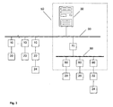
- FIG. 3 a conventional control system 90 is shown as an example which additionally control devices 10 according to the invention are connected.
- the conventional control system 90 includes an operator station 30 Control network 50 and a bus coupler 70, wherein the operator station 30 and the bus coupler 70 are connected to the control network 50. Furthermore is a field bus 80 is present, to which the bus coupler 70 and several conventional control devices 60 are connected.
- the conventional controllers 60 only communicate with the Operator station 30.
- the bus coupler 70 is provided, the Field bus 80 and the control network 50 interconnects and a Implementation of different communication protocols makes.
- control devices according to the invention 10 connected to the conventional control system 90.
- control units 10 according to the invention are connected to the fieldbus 80, but directly connected to the control network 50.
Landscapes
- Physics & Mathematics (AREA)
- General Physics & Mathematics (AREA)
- Engineering & Computer Science (AREA)
- Automation & Control Theory (AREA)
- Programmable Controllers (AREA)
- Remote Monitoring And Control Of Power-Distribution Networks (AREA)
Applications Claiming Priority (2)
| Application Number | Priority Date | Filing Date | Title |
|---|---|---|---|
| DE10349906A DE10349906A1 (de) | 2003-10-25 | 2003-10-25 | Steuergerät |
| DE10349906 | 2003-10-25 |
Publications (2)
| Publication Number | Publication Date |
|---|---|
| EP1530104A2 true EP1530104A2 (fr) | 2005-05-11 |
| EP1530104A3 EP1530104A3 (fr) | 2006-05-31 |
Family
ID=34428530
Family Applications (1)
| Application Number | Title | Priority Date | Filing Date |
|---|---|---|---|
| EP20040023530 Withdrawn EP1530104A3 (fr) | 2003-10-25 | 2004-10-02 | Appareil de commande |
Country Status (2)
| Country | Link |
|---|---|
| EP (1) | EP1530104A3 (fr) |
| DE (1) | DE10349906A1 (fr) |
Cited By (3)
| Publication number | Priority date | Publication date | Assignee | Title |
|---|---|---|---|---|
| EP2109259A1 (fr) | 2008-04-11 | 2009-10-14 | Phoenix Contact GmbH & Co. KG | Procédé, composant de bus et système de commande destinés à la commande à base d'Ethernet d'un système d'automatisation |
| CN102116813A (zh) * | 2009-11-27 | 2011-07-06 | 韦特柯格雷控制系统有限公司 | 电力切换模块的监测 |
| EP1098416B1 (fr) * | 1999-11-05 | 2018-04-25 | Siemens Industry, Inc. | Système de communication et de commande pour disjoncteur |
Families Citing this family (2)
| Publication number | Priority date | Publication date | Assignee | Title |
|---|---|---|---|---|
| DE102005015944A1 (de) | 2005-04-07 | 2006-10-12 | Abb Patent Gmbh | Elektrische Niederspannungsschaltanlage |
| DE102012105446B4 (de) | 2011-07-26 | 2018-07-26 | Endress+Hauser Conducta Gmbh+Co. Kg | Vorrichtung zur Bestimmung und/oder Überwachung einer chemischen oder physikalischen Prozessgröße in der Automatisierungstechnik |
Citations (7)
| Publication number | Priority date | Publication date | Assignee | Title |
|---|---|---|---|---|
| DE19826169A1 (de) * | 1998-06-13 | 1999-12-16 | Kaeser Kompressoren Gmbh | Elektronische Steuerung für Anlagen der Druckluft- und Vakuumerzeugung |
| DE19828219A1 (de) * | 1998-06-25 | 1999-12-30 | Hartmann & Braun Gmbh & Co Kg | Verfahren zur Zustandsüberwachung von elektromechanisch geschalteten Verbrauchern an speicherprogrammierbaren Steuerungen |
| US6047222A (en) * | 1996-10-04 | 2000-04-04 | Fisher Controls International, Inc. | Process control network with redundant field devices and buses |
| DE10012579A1 (de) * | 2000-03-15 | 2001-09-27 | Teamtechnik Maschinen Und Anla | Prozeßmodul für eine Bearbeitungsstation, Bearbeitungsstation und Verfahren zur Inbetriebnahme einer Bearbeitungsstation |
| US20020111948A1 (en) * | 1999-10-18 | 2002-08-15 | Nixon Mark J. | Interconnected zones within a process control system |
| DE10147744A1 (de) * | 2001-09-27 | 2003-01-23 | Siemens Ag | Bedienen und Beobachten eines Prozesses |
| WO2003075107A1 (fr) * | 2002-03-07 | 2003-09-12 | Omron Corporation | Dispositif de support d'evaluation de risque, produit-programme et procede pour commander un dispositif de support d'evaluation de risque a reseau de securite |
Family Cites Families (4)
| Publication number | Priority date | Publication date | Assignee | Title |
|---|---|---|---|---|
| DE9416303U1 (de) * | 1994-10-10 | 1994-12-15 | Abb Patent Gmbh, 68309 Mannheim | Antriebssteuereinrichtung |
| JP2002517850A (ja) * | 1998-06-10 | 2002-06-18 | シーメンス アクチエンゲゼルシヤフト | 機械、プラント又は器具の制御装置並びに制御監視方法 |
| AU2001261267A1 (en) * | 2000-08-07 | 2002-02-18 | Pni Corp. | Method and apparatus for a distributed home-automation-control (hac) window |
| AU2003217662A1 (en) * | 2002-02-25 | 2003-09-09 | General Electric Company | Protection system for power distribution systems |
-
2003
- 2003-10-25 DE DE10349906A patent/DE10349906A1/de not_active Withdrawn
-
2004
- 2004-10-02 EP EP20040023530 patent/EP1530104A3/fr not_active Withdrawn
Patent Citations (8)
| Publication number | Priority date | Publication date | Assignee | Title |
|---|---|---|---|---|
| US6047222A (en) * | 1996-10-04 | 2000-04-04 | Fisher Controls International, Inc. | Process control network with redundant field devices and buses |
| DE19826169A1 (de) * | 1998-06-13 | 1999-12-16 | Kaeser Kompressoren Gmbh | Elektronische Steuerung für Anlagen der Druckluft- und Vakuumerzeugung |
| DE19828219A1 (de) * | 1998-06-25 | 1999-12-30 | Hartmann & Braun Gmbh & Co Kg | Verfahren zur Zustandsüberwachung von elektromechanisch geschalteten Verbrauchern an speicherprogrammierbaren Steuerungen |
| US20020111948A1 (en) * | 1999-10-18 | 2002-08-15 | Nixon Mark J. | Interconnected zones within a process control system |
| DE10012579A1 (de) * | 2000-03-15 | 2001-09-27 | Teamtechnik Maschinen Und Anla | Prozeßmodul für eine Bearbeitungsstation, Bearbeitungsstation und Verfahren zur Inbetriebnahme einer Bearbeitungsstation |
| DE10147744A1 (de) * | 2001-09-27 | 2003-01-23 | Siemens Ag | Bedienen und Beobachten eines Prozesses |
| WO2003075107A1 (fr) * | 2002-03-07 | 2003-09-12 | Omron Corporation | Dispositif de support d'evaluation de risque, produit-programme et procede pour commander un dispositif de support d'evaluation de risque a reseau de securite |
| US7840430B2 (en) * | 2002-03-07 | 2010-11-23 | Omron Corporation | Risk evaluation support device, program product and method for controlling safety network risk evaluation support device |
Cited By (6)
| Publication number | Priority date | Publication date | Assignee | Title |
|---|---|---|---|---|
| EP1098416B1 (fr) * | 1999-11-05 | 2018-04-25 | Siemens Industry, Inc. | Système de communication et de commande pour disjoncteur |
| EP2109259A1 (fr) | 2008-04-11 | 2009-10-14 | Phoenix Contact GmbH & Co. KG | Procédé, composant de bus et système de commande destinés à la commande à base d'Ethernet d'un système d'automatisation |
| US8291142B2 (en) | 2008-04-11 | 2012-10-16 | Phoenix Contact Gmbh & Co. Kg | Method, bus components, and control system for ethernet-based control of an automation system |
| CN102116813A (zh) * | 2009-11-27 | 2011-07-06 | 韦特柯格雷控制系统有限公司 | 电力切换模块的监测 |
| EP2333570A3 (fr) * | 2009-11-27 | 2013-11-27 | Vetco Gray Controls Limited | Surveillance de modules de commutation de puissance |
| CN102116813B (zh) * | 2009-11-27 | 2015-06-03 | 通用电气石油和天然气英国有限公司 | 电力切换模块的监测 |
Also Published As
| Publication number | Publication date |
|---|---|
| DE10349906A1 (de) | 2005-05-25 |
| EP1530104A3 (fr) | 2006-05-31 |
Similar Documents
| Publication | Publication Date | Title |
|---|---|---|
| EP1168271B1 (fr) | Système de couplage d'un bus de terrain pour actionneurs ou capteurs | |
| EP4097927B1 (fr) | Adaptateur d'appareil basé sur spe pour connecter un appareil de terrain compatible non ethernet à un système de commande de processus basé sur ethernet | |
| DE102012014681B4 (de) | Verwendung eines lO-Links zur Anbindung eines Netzgerätes | |
| DE69715868T2 (de) | Abklemmbares elektrisches gerät mit einer ortsfesten einheit und einer entfernbaren und abklemmbaren einheit welche in der ortsfesten einheit installiert ist | |
| EP2438722B1 (fr) | Appareil de transfert des donnees pour la surveillance et le controle d'un systeme de procede distribue | |
| DE10304903A1 (de) | Vorrichtung zur Automatisierung und/oder Steuerung von Werkzeug- oder Produktionsmaschinen | |
| EP1611777B1 (fr) | Module basse tension | |
| DE10066242B4 (de) | Kommunikationsfähiger Leistungsschalter | |
| EP2093941B1 (fr) | Système de bus de terrain | |
| EP1364459B1 (fr) | Dispositif de commutation de securite | |
| EP1530104A2 (fr) | Appareil de commande | |
| EP1690390B1 (fr) | Procede de transmission de donnees via un bus de donnees, et systeme et passerelle permettant la mise en oeuvre dudit procede | |
| EP0792078B1 (fr) | Système d'interface pour capteurs-actionneurs | |
| EP1938356B1 (fr) | Surveillance d'un dispositif de protection monté en amont d'un appareillage de commutation | |
| EP2369694B1 (fr) | Dispositif de raccordement et appareil d'automatisation | |
| EP3161952B1 (fr) | Alimentation à découpage doté d'interface web | |
| EP2778811A1 (fr) | Dispositif pour un système d'interface AS | |
| EP1619565B1 (fr) | Procédure et dispositif pour commuter sûrement un système d'automatisation avec bus. | |
| DE102010038459A1 (de) | Sicherheitssystem | |
| EP2079141B1 (fr) | Dispositif de démarrage pour un moteur électrique doté d'une technique de sécurité intégrée | |
| DE102023112683A1 (de) | Station zum Einsatz in einem Feldnetz zwischen einem oder mehreren Feldgeräten und einer Zentraleinheit, sowie dazugehöriges Feldnetz | |
| WO1994024647A1 (fr) | Armoire de commande avec bus de donnees | |
| EP1734455B1 (fr) | Adressage d'une unité esclave dans un système maître-esclave | |
| DE10243771A1 (de) | Vorrichtung zur Automatisierung und/oder Steuerung von Werkzeug- oder Produktionsmaschinen | |
| DE202010004548U1 (de) | Funktionseinheit zur Steuerung und/oder Überwachung eines Antriebs |
Legal Events
| Date | Code | Title | Description |
|---|---|---|---|
| PUAI | Public reference made under article 153(3) epc to a published international application that has entered the european phase |
Free format text: ORIGINAL CODE: 0009012 |
|
| AK | Designated contracting states |
Kind code of ref document: A2 Designated state(s): AT BE BG CH CY CZ DE DK EE ES FI FR GB GR HU IE IT LI LU MC NL PL PT RO SE SI SK TR |
|
| AX | Request for extension of the european patent |
Extension state: AL HR LT LV MK |
|
| PUAL | Search report despatched |
Free format text: ORIGINAL CODE: 0009013 |
|
| AK | Designated contracting states |
Kind code of ref document: A3 Designated state(s): AT BE BG CH CY CZ DE DK EE ES FI FR GB GR HU IE IT LI LU MC NL PL PT RO SE SI SK TR |
|
| AX | Request for extension of the european patent |
Extension state: AL HR LT LV MK |
|
| 17P | Request for examination filed |
Effective date: 20061124 |
|
| AKX | Designation fees paid |
Designated state(s): AT BE BG CH CY CZ DE DK EE ES FI FR GB GR HU IE IT LI LU MC NL PL PT RO SE SI SK TR |
|
| 17Q | First examination report despatched |
Effective date: 20081016 |
|
| RAP1 | Party data changed (applicant data changed or rights of an application transferred) |
Owner name: ABB AG |
|
| RIC1 | Information provided on ipc code assigned before grant |
Ipc: G05B 19/042 19950101ALI20180926BHEP Ipc: H02H 7/26 19680901AFI20180926BHEP |
|
| RIC1 | Information provided on ipc code assigned before grant |
Ipc: G05B 19/042 20060101ALI20180926BHEP Ipc: H02H 7/26 20060101AFI20180926BHEP |
|
| STAA | Information on the status of an ep patent application or granted ep patent |
Free format text: STATUS: THE APPLICATION IS DEEMED TO BE WITHDRAWN |
|
| 18D | Application deemed to be withdrawn |
Effective date: 20200603 |