EP1099563B1 - Zusammengesetztes Aufzeichnungsmaterial und dessen Herstellungsverfahren, Aufnahmematerialsatz und Aufzeichnungsverfahren - Google Patents
Zusammengesetztes Aufzeichnungsmaterial und dessen Herstellungsverfahren, Aufnahmematerialsatz und Aufzeichnungsverfahren Download PDFInfo
- Publication number
- EP1099563B1 EP1099563B1 EP00124756A EP00124756A EP1099563B1 EP 1099563 B1 EP1099563 B1 EP 1099563B1 EP 00124756 A EP00124756 A EP 00124756A EP 00124756 A EP00124756 A EP 00124756A EP 1099563 B1 EP1099563 B1 EP 1099563B1
- Authority
- EP
- European Patent Office
- Prior art keywords
- recording medium
- parts
- composite
- recording
- ink
- Prior art date
- Legal status (The legal status is an assumption and is not a legal conclusion. Google has not performed a legal analysis and makes no representation as to the accuracy of the status listed.)
- Expired - Lifetime
Links
Images






Classifications
-
- G—PHYSICS
- G03—PHOTOGRAPHY; CINEMATOGRAPHY; ANALOGOUS TECHNIQUES USING WAVES OTHER THAN OPTICAL WAVES; ELECTROGRAPHY; HOLOGRAPHY
- G03G—ELECTROGRAPHY; ELECTROPHOTOGRAPHY; MAGNETOGRAPHY
- G03G7/00—Selection of materials for use in image-receiving members, i.e. for reversal by physical contact; Manufacture thereof
-
- B—PERFORMING OPERATIONS; TRANSPORTING
- B41—PRINTING; LINING MACHINES; TYPEWRITERS; STAMPS
- B41J—TYPEWRITERS; SELECTIVE PRINTING MECHANISMS, i.e. MECHANISMS PRINTING OTHERWISE THAN FROM A FORME; CORRECTION OF TYPOGRAPHICAL ERRORS
- B41J11/00—Devices or arrangements of selective printing mechanisms, e.g. ink-jet printers or thermal printers, for supporting or handling copy material in sheet or web form
- B41J11/008—Controlling printhead for accurately positioning print image on printing material, e.g. with the intention to control the width of margins
-
- B—PERFORMING OPERATIONS; TRANSPORTING
- B41—PRINTING; LINING MACHINES; TYPEWRITERS; STAMPS
- B41J—TYPEWRITERS; SELECTIVE PRINTING MECHANISMS, i.e. MECHANISMS PRINTING OTHERWISE THAN FROM A FORME; CORRECTION OF TYPOGRAPHICAL ERRORS
- B41J11/00—Devices or arrangements of selective printing mechanisms, e.g. ink-jet printers or thermal printers, for supporting or handling copy material in sheet or web form
- B41J11/36—Blanking or long feeds; Feeding to a particular line, e.g. by rotation of platen or feed roller
- B41J11/42—Controlling printing material conveyance for accurate alignment of the printing material with the printhead; Print registering
-
- B—PERFORMING OPERATIONS; TRANSPORTING
- B41—PRINTING; LINING MACHINES; TYPEWRITERS; STAMPS
- B41M—PRINTING, DUPLICATING, MARKING, OR COPYING PROCESSES; COLOUR PRINTING
- B41M5/00—Duplicating or marking methods; Sheet materials for use therein
- B41M5/50—Recording sheets characterised by the coating used to improve ink, dye or pigment receptivity, e.g. for ink-jet or thermal dye transfer recording
- B41M5/502—Recording sheets characterised by the coating used to improve ink, dye or pigment receptivity, e.g. for ink-jet or thermal dye transfer recording characterised by structural details, e.g. multilayer materials
- B41M5/506—Intermediate layers
-
- B—PERFORMING OPERATIONS; TRANSPORTING
- B41—PRINTING; LINING MACHINES; TYPEWRITERS; STAMPS
- B41M—PRINTING, DUPLICATING, MARKING, OR COPYING PROCESSES; COLOUR PRINTING
- B41M5/00—Duplicating or marking methods; Sheet materials for use therein
- B41M5/50—Recording sheets characterised by the coating used to improve ink, dye or pigment receptivity, e.g. for ink-jet or thermal dye transfer recording
- B41M5/52—Macromolecular coatings
-
- G—PHYSICS
- G03—PHOTOGRAPHY; CINEMATOGRAPHY; ANALOGOUS TECHNIQUES USING WAVES OTHER THAN OPTICAL WAVES; ELECTROGRAPHY; HOLOGRAPHY
- G03G—ELECTROGRAPHY; ELECTROPHOTOGRAPHY; MAGNETOGRAPHY
- G03G5/00—Recording-members for original recording by exposure, e.g. to light, to heat or to electrons; Manufacture thereof; Selection of materials therefor
Definitions
- the present invention relates to a composite recording medium wherein two or more types of parts having different surface properties are integrated, a manufacturing method therefor, and a set of two or more types of recording mediums having different surface properties.
- the present invention relates to a composite recording medium wherein two or more parts having different surface properties are integrated, capable of most effectively obtaining ink images having desired image quality, and exhibiting outstanding productivity in terms of obtaining images with a plurality of image qualities at one time, a manufacturing method and recording method therefor, recordings wherein ink images are recorded using the same, and a recording medium set containing the same.
- the surface for forming images is of even quality, and it is necessary to do re-recording in cases where the image quality of the recorded image obtained does not match the preference of the image producer, or in cases where it is desired to use another recording medium and compare the quality of the recorded images.
- the use of such recording mediums has proven ineffective in obtaining recorded images exhibiting the desired image quality, it being necessary, for example, to make repeated trial printings until the quality of the recorded image obtained corresponds to personal preference.
- an object of the present invention is to provide a recording medium wherewith the problems noted above can be resolved and recorded images having the desired image quality can be obtained most effectively.
- Another object of the present invention is to provide a recording medium exhibiting outstanding productivity in that an image having a plurality of image qualities can be obtained in one operation.
- Yet another object of the present invention is to provide a recording medium for use in making trial printings.
- Yet another object of the present invention is to provide a set of recording mediums wherewith trial printings can be made.
- Yet another object of the present invention is to provide a recording medium wherewith it is possible to make trial printings with one sheet of recording paper.
- EP-A-0791474 discloses a recording medium having faces with different ink absorption capacity, brightness and glossiness, whereas the double-side ink jet recording sheet of JP-A-8002089 may be provided with different raw papers on the two sides of the sheet, each with its own ink receptivity.
- EP-A-0742107 discloses an ink jet recording medium with a recording layer on only one side, the recording side being smoother than the opposite side.
- GB-A-1300319 relates to a moisture resistant synthetic cardboard provided with webs of paper on both surfaces, which may differ in their properties.
- EP-A-0807538 discloses an identity card consisting of a synthetic resin substrate and an engraving layer formed by a smooth-faced silver film. A photograph of a face and characters for identification are printed through thermo-transfer technique on the silver film. The photograph is also reproduced as an engraving.
- the credit card disclosed in US-A-3 902 262 is made of vinyl or other suitable support material, it has an area for printing or embossing information for identification purposes, an area printed with a repeating pattern of vertical bars of magnetic material, and a signature panel
- the present invention which is based on those research findings, provides a composite recording medium that is characterized by having two or more types of parts exhibiting different surface properties integrated therein.
- different surface properties is meant that the surface properties differ in outward appearance. Even if the surface (uppermost face) is uniformly smooth, the surface properties are considered to be different if there is the appearance of difference due to the effects of an internal layer therein. More specifically, in the case of a recording medium wherein a resin coating layer is formed having two or more types of face properties on a substrate, and an ink accepting layer is formed as a surface layer (uppermost layer) on that resin coating layer, the surface properties are considered to differ if the parts noted appear to differ, in terms of external appearance, due to the face properties of that resin coating layer, even though the surface be uniformly smooth.
- the composite recording medium of the invention is as defined by appended claim 1.
- Claim 6 defines a method to manufacture the composite recording medium. Further embodiments are as set forth in the dependent claims.
- Fig. 1 is a section of the first embodiment aspect of the composite recording medium of the present invention.
- the composite recording medium 100 in the first embodiment aspect is configured of a substrate 101, a transparent ink accepting layer 103 deployed on the substrate 101 over an intervening resin coating layer 102, and a resin coating layer 104 deployed on the back surface (the face on the opposite side from the ink accepting layer 103) of the substrate 101.
- the resin coating layer 102 on the substrate 101 comprises two or more types of parts having differing face properties.
- the composite recording medium 100 of this embodiment aspect has two or more parts having different surface properties integrated therein.
- the face properties of the resin coating layer 102 do not appear in Fig. 1 , but when represented by a plan (i.e. the plan of the composite recording medium 100 from which the ink accepting layer 103 has been omitted), those face properties do appear.
- the two or more parts having the different surface properties use may be made of two or more parts having different glossiness, or two or more parts having different smoothness, or two or more parts differing in both glossiness and smoothness. More specifically, the two or more types of parts may be two or more types of parts selected from a group made up of glossy tone parts, semi-glossy tone parts, matte tone parts, and silk-weave tone parts. Among these parts, moreover, one or more can have a plurality of recording areas divided according to the strength or weakness of the light reflectance thereof.
- the substrate 101 used in this embodiment aspect there is no particular limitation, and commonly used paper can be employed, but it is preferable that this be smooth, high-density stencil paper such as is used as the substrate (supporting body) for photographs.
- polyolefin resins used for thermally melting extrusion coatings are preferable, with polyethylene resins being particularly preferable.
- the method for forming the resin coating layers 102 and 104 on both sides of the substrate 101 may be, besides the thermally melting extrusion coating method alluded to above, a method whereby a latex capable of forming a film is coated. It is possible, for example, to coat the substrate 101 with a latex having a low minimum film-forming temperature (MFT) and then heating to a temperature that is equal to or higher than that minimum film-forming temperature (cf. Japanese Patent Application Laid-Open No. H11-198966/1999 ).
- MFT low minimum film-forming temperature
- the ink accepting layer 103 used in this embodiment aspect is a layer for reproducing color images and photographic images and the like at high quality. Any of the materials known in the prior art can be used as the material for forming this ink accepting layer 103. More specifically, it is preferable that the ink accepting layer contain an ink absorbing pigment, an ink fixing agent, and a binder, but also containing, as necessary, various types of additives such as dye fixing agents (water resistance enhancing agents), fluorescent brightening agents, surfactants, antifoaming agents, pH adjusting agents, anti-molding agents, UV absorbers, and anti-oxidants.
- dye fixing agents water resistance enhancing agents
- fluorescent brightening agents surfactants
- antifoaming agents surfactants
- antifoaming agents surfactants
- UV absorbers and anti-oxidants
- the ink accepting layer 103 is formed by dissolving or dispersing the binder noted above in a suitable solvent, adding thereto the ink fixing agent, adding the various additives noted above as necessary, then coating the resulting coating liquid onto the resin coating layer 102 by a known coating method such as roller coating, spray coating, rod bar coating, or air knife coating, and causing that to dry.
- the composite recording medium 100 in the first embodiment aspect can be fabricated, for example, by forming the resin coating layers 102 and 104 on the substrate 101 and on the back side thereof, then imparting two or more types of face properties to the resin coating layer 102 by rolling, next forming the ink accepting layer 103 on the resin coating layer 102 after the face properties have been imparted thereto, and thus imparting two or more types of surface properties.
- the roller used here may be a rotogravure roller, for example, which can be used to emboss the resin coating layer 102 and thereby to impart two or more types of face properties thereto.
- the composite recording mediums of the present invention are used in the following way, for example. That is, when the composite recording medium 400 of the invention is used, as diagrammed in Fig. 2 , by recording the same image (a star shape is used as an example in Fig. 2 ) a plural number of times, a recording wherein the same image is recorded a plurality of times is obtained. After that, the surface property is selected wherein is formed an ink image having the desired surface property, from that recording, and the ink image is recorded on a recording medium the entire surface of which has the same surface property as that selected surface property. In this manner, images having the desired image quality and recordings containing those images can be obtained most effectively. Needless to say, furthermore, the images obtained here are vivid, high-resolution images.
- the composite recording mediums of the present invention are preferably used as trial recording mediums for recording ink images of desired image quality. Also, by providing a recording medium set containing pluralities of the composite recording mediums of the present invention and recording mediums wherein the overall surface exhibits a surface property that is the same as one surface property of the plurality of surface properties exhibited by that composite recording medium, respectively, so that those recording mediums contain all of the types of that plurality of surface properties, ink images having desired image quality can be obtained most effectively and enhanced utility is also realized.
- the composite recording mediums of the present invention are preferably used as mediums for ink jet recording.
- the composite recording mediums of the present invention in addition, can be used as mediums for bubble jet recording, mediums for recording by a writing instrument such as a pen, and as mediums for recording by various other types of printing schemes that use liquid ink.
- the composite recording mediums of the present invention can be used as recording mediums whereon toner is heated and fixed in an electronic photographic recording scheme such as is used in a copier or printer, or as recording mediums used for labels provided with an adhesive layer.
- the ink accepting layer 103 in place of the ink accepting layer 103, it is possible to use a layer provided with a gap containing organic particles to which are bonded an organic cationic polymer (cf. Japanese Patent Application Laid-Open No. H11-58942/1999 ), or a layer obtained by using inorganic particles, a water soluble resin, and a prescribed crosslinking agent, crosslinking that water soluble resin while a constant drying rate is indicated, and effecting hardening (cf. Japanese Patent Application Laid-Open No. H11-115308/1999 ), etc. It is also possible to change to a layer for accepting ink described in Japanese Patent Application Laid-Open Nos. H10-81064/1998 , No.
- FIG. 3 One example of a composite recording medium wherein two or more types of parts having differing surface properties are integrated is diagrammed in Fig. 3 .
- the composite recording medium 700 diagrammed in Fig. 3 is configured by a glossy tone part 71 and a silk-weave tone part 72.
- the glossy tone part 71 for example, can be used as an image printing area and the silk-weave tone part 72 can be used as a text printing area.
- recording paper can be provided wherewith the printing application in each printing area is conformed with.
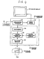
- Fig. 4 is a block diagram of the configuration of a 1; print processing apparatus (dot recording apparatus).
- the print processing apparatus is configured such that it comprises a scanner 10, a computer terminal 20, and a color printer 30.
- the computer terminal 20 comprises a color display 40.
- the scanner 10 reads color image data from original color copy, and sends primary color image data consisting of the three colors R (red), G (green), and B (blue) to the computer terminal 20.
- an application program 21, video driver 22, and printer driver 23 run under an operating system.
- the print driver 23 takes image data from the application program 21 and performs image processing to convert those data into signals that are printable by a color sprinter 30, that is, into binaryconverted signals Y (yellow), M (magenta), C (cyan), and K (black).
- a color display 40 displays images indicating how that image processing is proceeding based on instructions from the video driver 22.
- the video driver 22 also controls operating screens for the application program 21.
- the printer driver 23 comprises a rasterizer 24, color correction module 25, halftone module 26, and color correction table 27.
- the rasterizer 24 converts the image data handled by the application program 21 to color information in dot units.
- the color correction module 25 references the color correction table 27, subjects the image data (RGB 256 tone data) converted to dot units to color correction according to the characteristics of the colors produced by the color printer 30, converting those data to YMCK image data.
- the color correction table 27 is read by the printer driver 23 from the color printer 30 when the computer terminal 20 is started up.
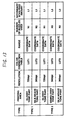
- Fig. 13 also represents a recording mode table wherein are registered color correspond tables and recording modes for various types of composite recording medium.
- a type 1 composite recording medium comprises two types of printing areas, namely a glossy tone part and a silk-weave tone part, for each of which are registered, respectively, a color correction table, range (coordinate data representing printing area positions on the composite recording medium), number of nozzles used N, and secondary scan feed amount L, etc.
- the number of nozzles used N and the secondary scan feed amount L are recording mode parameters used when printing images or text in the respective printing areas.
- the recording mode parameters in addition to the number of nozzles used N and the secondary scan feed amount L, also include such parameters as nozzle pitch k and number of scan repetitions s, but these are not described further in the interest of expedience.
- a type 2 composite recording medium is configured of three types of printing area, namely a glossy tone part, a semiglossy tone part, and a silk-weave tone part.
- the glossy tone part can be used as a printing area for images of high image quality
- the semiglossy tone part as a printing area for images of low image quality
- the silk-weave tone part as a text printing area, for example.
- For these printing areas are registered resolution levels, color correction tables, ranges, number of nozzles used N, and secondary scan feed amount L, etc.
- the color correction module 25 When the user inputs a type for the composite recording medium 700 following directions displayed on the screen of the color display 40, the color correction module 25 references the corresponding look-up table from the color correction table 27 and performs color correction.
- the type of the composite recording medium 700 is type 1, wherefore the user operates the computer terminal 20 to indicate that the type is type 1.
- the color correction module 25 determines the positions of the glossy tone part and silk-weave tone part from the coordinate data for each printing area registered in the recording mode table, performs color correction for the glossy tone part referencing LUT1, and performs color correction for the silk-weave tone part referencing LUT2.
- the halftone module 26 performs halftone processing that expresses density in some area by the presence or absence of ink in dot units from image data after they have been color corrected. For the halftone processing there are dithering and error dispersion, etc.
- the printer driver 23 sends the YMCK binary-converted image data to the color printer 30. Also included in those image data are text data that are binary-converted by the absence or presence of dots.
- the color printer 30 prints the prescribed text and images, etc., on the composite recording medium 700 on the basis of the image data supplied from the printer driver 23.
- color image data are input from the scanner 10, but color image data may also be input from a digital still camera or video camera, etc.
- printer driver 23 operating on computer terminal 20 converts via application program 21 the color image data of RGC fetched from scanner 10 to a printable image data, in short, a multivalued image data of YMCK at color printer 30, and supplies the multivalued image data to color printer 30.
- color printer 30 it is possible to embed a function which corresponds to printer driver 23 in color printer 30 so that the color image data fetched from scanner 10 is provided with the preferable image processings in the color printer 30 such as color conversion, color amendment, and half tone processing, etc., and the multivalued image data of YMCK is gained.
- the image processing in color printer 30 can be performed by software but it is also can be performed by providing an exclusive hardware.
- Fig. 5 is a simplified configurational diagram of a printer engine unit in the color printer 30.
- the color printer 30 comprises a mechanism for conveying the composite recording medium 700 by a paper feed motor 51, a mechanism for causing a carriage 60 to move back and forth in the direction of the shaft of a platen 52 by a carriage motor 53, a mechanism for driving a print head 63 mounted on the carriage 60 and controlling ink ejection and dot recording, and a control circuit 81 for controlling the operations of the paper feed motor 51, carriage motor 53, and print head 63.
- the print head 63 position information is sent to the control circuit 81.
- the control circuit 81 comprises a non-volatile memory 82 that stores the recording mode table described earlier, and controls the operations of the print head 63, paper feed motor 51, and carriage motor 53 while referencing that recording mode table. (A more detailed description is given further below.)
- the recording mode table is read out from the non-volatile memory 82 by the printer driver 23 when the computer terminal 20 is started up. Some of the data in the recording mode table are used as the color correction table 27 in the color correction processing for the image data read in from the scanner 10.
- An operating panel 83 is connected to the control circuit 81.
- a rewritable non-volatile memory such, for example, as an EEPROM (electronically erasable and programmable read only memory) or UV-EPROM (ultraviolet erasable programmable read only memory) can be used.
- EEPROM electronically erasable and programmable read only memory
- UV-EPROM ultraviolet erasable programmable read only memory
- the carriage 60 is capable of having mounted therein a black ink cartridge 61 and a color ink cartridge 62 containing ink of the three colors cyan, magenta, and yellow.
- a black ink cartridge 61 and a color ink cartridge 62 containing ink of the three colors cyan, magenta, and yellow.
- To the print head 63 in the lower part of the carriage 60 are attached a total of four ink ejecting heads 64 to 67, and in the bottom of the carriage 60 are erected induction lines for inducting ink from ink tanks to these heads for the several colors.
- the black ink cartridge 61 and the color ink cartridge 62 are mounted in the carriage from the top, the induction lines are inserted into connection holes provided in the cartridges, making it possible for ink to be supplied from the ink cartridges to the ink ejecting heads 64 to 67.
- the ink ejection mechanism in the ink ejection head 64 is next described.
- Fig. 6 when the ink cartridge 61 is mounted at the induction hole 66, ink inside the ink cartridge 61 is sucked out through the induction line 66, by means of capillary action, and delivered to the ink ejection head 64 of the print head 63 deployed in the lower part of the carriage 60.
- Fig. 7 a plural number of nozzles 90 is provided in the ink ejection head 64, and a piezoelectric element 80 that is one type of electrostriction element is deployed for each nozzle 90.
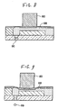
- Fig. 8 and Fig. 9 are sections of the ink ejection head 64.
- the piezoelectric element 80 is an electromechanical conversion element, wherein a crystal structure is distorted by the application of a voltage, that converts electrical energy to mechanical energy.
- Fig. 8 represents a condition wherein no voltage is being applied across the electrodes provided at both ends of the piezoelectric element 80.
- the piezoelectric element 80 expands for the time that the voltage is applied, causing one side wall of a pressurized chamber (cavity) 68 to be deformed.
- the volume of the pressurized chamber 68 contracts in response to the expansion of the piezoelectric element 80, whereupon ink corresponding in volume to the amount of that contraction becomes an ink droplet 69 which is ejected at high speed from the tip of the nozzle 90.
- Dot recording is performed by this ink droplet 69 impacting the composite recording medium 700 that is conveyed by the platen 52.
- the description given here relates to the configuration of the ink ejection head 64, but the ink ejection heads 65 to 67 have the same configuration.
- the color printer 30 while turning the platen 52 by the paper feed motor 51 to convey the composite recording medium 700, causes the carriage 60 to move back and forth by the carriage motor 53, simultaneously drives the ink ejection heads 64 to 67 provided in the print head 63 to eject the ink of each color, and forms text and images, etc., in multiple colors, on the composite recording medium 700.
- Fig. 10 is an explanatory diagram representing an array of ink jet nozzles in the ink ejection heads 64 to 67.
- the ink ejection head 64 is deployed a nozzle array for ejecting black ink.
- the ink ejection heads 65 to 67 are deployed nozzle arrays for ejecting, respectively, cyan, magenta, and yellow ink.
- the positions of these four nozzle array groups are mutually coincidental in the secondary scanning direction.
- the four nozzle array groups each comprise a plural number of nozzles 90 arranged in a staggered formation with a constant nozzle pitch k in the secondary scanning direction.
- Fig. 11 represents an array of a plurality of dots formed by one nozzle array.
- drive signals are supplied to the piezoelectric elements 80 in the nozzles so that the plural number of dots recorded by one nozzle array line up in roughly a straight line in the secondary scanning direction.
- Fig. 10 for example, in the case where the nozzle array is arrayed in a staggered formation, the case is considered where dots are recorded as the ink ejection head 61 is scanned in the rightward direction, in the figure.
- the leading nozzle groups 91 and 93 are sent a drive signal at a timing that is faster by d/v (seconds) than the timing wherewith the drive signal is sent to the following nozzle groups 92 and 94.
- d (in inches) is the pitch between two nozzle groups in the ink ejection head 61
- v (in inches/second) is the scanning speed of the ink ejection head 61.
- the multiple nozzles provided in the ink ejection heads 64 to 67 are not limited to being always all used. Depending on the recording mode, there are also cases where only a portion thereof is used.
- Fig. 12 is a functional block diagram for a configuration relating to drive control corresponding to a recording mode.
- a recording mode setting unit 31 recording mode table 32, raster data storage unit 33, drive unit controller 34, primary scan drive unit 35, secondary scan drive unit 36, print head drive unit 37, print head 63, and composite recording medium 700.
- the recording mode table 32 is the recording mode table diagrammed in Fig. 13 , which is stored in the non-volatile memory 82. In this same table are registered the recording mode parameters and color correction tables for each of the printing areas configuring the composite recording medium, etc.
- the recording mode setting unit 31, raster data storage unit 33, and drive unit controller 34 are implemented by circuitry inside the control circuit 81.
- the primary scan drive unit 35 is implemented by the carriage 60 feed mechanism that includes the carriage motor 53, while the secondary scan drive unit 36 is implemented by the recording medium 700 feed mechanism that includes the paper feed motor 51.
- the print head drive unit 37 is implemented by a circuit that includes the piezoelectric elements 80 for the nozzles 90.
- the recording mode setting unit 31 distinguishes the type of the composite recording medium 700 from the image data header, and fetches the corresponding recording mode parameters from the recording mode table 32.
- the recording mode parameters include such parameters as are required for dot recording, such as the ranges of the print areas, the number of nozzles used N, and the secondary scan feed amount L.
- the number of nozzles used is N1 and the secondary scan feed amount is L1 for the glossy tone part configuring the composite recording medium 700
- the number of nozzles used is N2 and the secondary scan feed amount is L2 for the silk-weave tone part.
- the recording mode parameters such as the number of nozzles used N and the secondary scan feed amount L differ for each printing area. Therefore the recording mode setting unit 31, based on the print head 63 position information sent from the position detection sensor 57, determines whether the printing area that will be the object of dot recording in the next primary scan is a glossy tone part or a silk-weave tone part.
- the recording mode setting unit 31 sends the number of nozzles used N1 and secondary scan feed amount L1 as recording mode parameters to the raster data storage unit 33 and the drive unit controller 34.
- the recording mode setting unit 31 sends the number of nozzles used N2 and the secondary scan feed amount L2 as recording mode parameters to the raster data storage unit 33 and the drive unit controller 34. The sending of these recording mode parameters is done prior to the previous scan.
- the raster data storage unit 33 based on the recording mode parameters sent from the recording mode setting unit 31, stores image data in a buffer memory (not shown). Meanwhile, the drive unit controller 34, in response to the recording mode parameters sent from the recording mode setting unit 31, controls the primary scan drive unit 35, secondary scan drive unit 36, and print head drive unit 37.
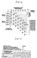
- Fig. 14 is an explanatory diagram for the recording mode parameters.
- one example of secondary scan feed in the case where four nozzles are used is represented in order to simplify the explanation.
- the solid line circles containing numerals indicate the positions in the secondary scanning direction of the four nozzles 90 after each secondary scan feed.
- the numerals 0 to 3 inside the circles are nozzle numbers.
- the four nozzle positions are fed in the secondary scan direction every time one primary scan ends. In actuality, however, the feed in the secondary scanning direction is implemented by conveying the composite recording medium 700 with the paper feed motor 51.
- the secondary scan feed amount L is the constant value of 2 dots.
- the positions of the four nozzles 90 shift by 2 dots at a time in the secondary scanning direction every time the secondary scan is effected.
- the nozzle pitch k is 3 dots
- the number of nozzles used N is 4.
- the number of nozzles used is the number of nozzles actually used of the plurality of nozzles mounted.
- the number of scan repetitions s means that dots are recorded intermittently every s-1 dots in one primary scan. Accordingly, the number of scan repetitions s is also equal to the number of nozzles used for recording all the dots on one raster.
- the offset F is a value that, having arbitrarily established the periodic position of the first nozzle where a secondary scan feed is not effected (a position recurring every 4 dots in Fig. 14 ) as a reference position at offset 0, indicates by how many dots the position of the nozzle after a secondary scan feed is removed from that reference position in the secondary scanning direction.
- the nozzle offset F is returned to 0 by the third secondary scan feed, wherefore, taking three secondary scan feeds as one small cycle, by repeating that small cycle, all of the dots on the raster in the effective recording range can be recorded.
- the description given in the foregoing is for the printing processing of a composite recording medium wherein, in terms of printing area, two or more types of parts having different surface properties are integrated.
- a composite recording medium wherein, in terms of printing area, two or more types of parts exhibiting different glossiness and/or different smoothness are integrated may be used.
- the two or more types of parts moreover, may be two or more types of parts selected from a group made up of glossy tone parts, semiglossy tone parts, matte tone parts, and silk-weave tone parts. Of those two or more types of parts, furthermore, one or more of those parts may have multiple recording areas distinguished by the strength or weakness of the light reflectance exhibited thereby.
- the composite recording medium used in the dot recording processing in the present invention may be one comprising a base material, a resin coating layer made up of two or more types of parts having different face properties, and an ink accepting layer deployed with that resin coating layer intervening.
- composite recording medium used in the present invention include machine glazed paper, greeting cards (post cards) and the like in which two or more types of parts having different surface properties are integrated.
- the present invention can also be applied to printing that represents multiple gradations by representing one pixel with a plurality of dots. It can also be applied in a drum scan printer. With a drum scan printer, however, the direction in which the drum turns will be the primary scanning direction, and the direction in which the carriage travels will be the secondary scanning direction.
- the present invention can be applied not only to ink jet printers, but more generally in dot recording apparatuses that make recordings on the surface of a composite recording medium using recording heads having plural dot recording element arrays.
- the functions implemented in hardware may be implemented instead in software, and, conversely, some of the functions implemented by software may be implemented instead in hardware.
- the functions implemented with the control circuit 81 of the color printer 30 may be configured so that they are performed by the computer terminal 20. In that case, programs such as the printer driver 23 will implement functions equivalent to those implemented by the control circuit 81.
- composite recording mediums are provided wherewith it is possible most effectively to obtain recorded images having the desired image quality.
- composite recording mediums are provided that afford outstanding productivity in that images having multiple image qualities can be obtained at one time.
- a recording method and manufacturing method for composite recording mediums wherewith recorded images having the desired image quality are obtained most effectively are provided.
- recordings having recorded images exhibiting the desired image quality are provided.
- a recording medium set is provided wherewith recorded images can most effectively be obtained which exhibit the desired image quality.
- color correction processing and dot recording processing can be implemented that are suitable, respectively, to two or more types of parts configuring a composite recording medium, wherefore high-image-quality dot recording processing can be effected without dramatically lowering the dot recording processing speed in the composite recording medium overall.
Landscapes
- Physics & Mathematics (AREA)
- General Physics & Mathematics (AREA)
- Ink Jet (AREA)
- Ink Jet Recording Methods And Recording Media Thereof (AREA)
- Paper (AREA)
- Duplication Or Marking (AREA)
- Thermal Transfer Or Thermal Recording In General (AREA)
Claims (9)
- Zusammengesetztes Aufzeichnungsmedium (100), das umfasst:ein Trägermaterial (101);eine Harz-Überzugschicht (102), die auf das Trägermaterial (101) aufgetragen ist, und eine Tintenaufnahmeschicht (103), die auf die Harz-Überzugschicht (102) so aufgetragen ist, dass die Harz-Überzugschicht (102) zwischen dem Trägermaterial (101) und der Tinten-Aufnahmeschicht (103) angeordnet ist,dadurch gekennzeichnet, dassdie Harz-Überzugschicht (102) an einer Fläche derselben zwei oder mehr Teile hat, die unterschiedlichen Glanz und/oder Glätte aufweisen.
- Zusammengesetztes Aufzeichnungsmedium nach Anspruch 1, wobei die zwei oder mehr Teile zwei oder mehr Teile sind, die aus einer Gruppe ausgewählt werden, die aus glänzenden Teilen, halbglänzenden Teilen, matten Teilen und seidenmatten Teilen besteht.
- Zusammengesetztes Aufzeichnungsmedium nach Anspruch 2, wobei von den zwei oder mehr Teilen ein oder mehr Teile eine Vielzahl von Aufzeichnungsbereichen aufweist/aufweisen, die sich durch die Stärke bzw. Schwäche des Lichtreflektionsvermögens unterscheiden, das sie aufweisen.
- Zusammengesetztes Aufzeichnungsmedium nach Anspruch 1, wobei das zusammengesetzte Aufzeichnungsmedium (100) ein Tintenstrahl-Aufzeichnungsmedium ist.
- Zusammengesetztes Aufzeichnungsmedium nach Anspruch 1, wobei das zusammengesetzte Aufzeichnungsmedium (100) ein Versuchs-Aufzeichnungsmedium zum Aufzeichnen von Tintenbildern gewünschter Bildqualität ist.
- Verfahren zum Herstellen eines zusammengesetzten Aufzeichnungsmediums, bei dem:eine Harz-Überzugschicht (102) auf einem Trägermaterial (101) ausgebildet wird; und eine Tintenaufnahmeschicht (103) auf der Harz-Überzugschicht (102) ausgebildet wird,dadurch gekennzeichnet, dassverschiedenen Teilen der Harz-Überzugschicht (102) nach Ausbilden der Harz-Überzugschicht (102) auf dem Trägermaterial (101) mit Walzen zwei oder mehr Typen von Glanz und/oder Glätte verliehen werden;die Tinten-Aufnahmeschicht (103) auf der Harz-Überzugschicht ausgebildet wird, nachdem Glanz und/oder Glätte verliehen worden sind;so dass das zusammengesetzte Aufzeichnungsmedium zwei oder mehr Typen von Glanz und/oder Glätte aufweist.
- Aufzeichnung, die eine Aufzeichnung des gleichen Tintenbildes in jedem der Teile des mit dem Herstellungsverfahren nach Anspruch 6 erzeugten zusammengesetzten Aufzeichnungsmediums umfasst, die unterschiedlichen Glanz und/oder unterschiedliche Glätte aufweisen.
- Verfahren zum Aufzeichnen auf ein zusammengesetztes Aufzeichnungsmedium, bei dem unter Verwendung eines mit dem Herstellungsverfahren nach Anspruch 6 gewonnenen Aufzeichnungsmediums das gleiche Tintenbild in jedem der Teile desselben aufgezeichnet wird, die unterschiedlichen Glanz und/oder unterschiedliche Glätte haben.
- Satz von Aufzeichnungsmedien, der eine Vielzahl mit dem Herstellungsverfahren nach Anspruch 6 gewonnener zusammengesetzter Aufzeichnungsmedien und eine Vielzahl von Aufzeichnungsmedien umfasst, deren gesamte Oberfläche den gleichen Glanz und/oder die gleiche Glätte wie einer der Vielzahl von Typen von Glanz und/oder Glätte aufweist, die die Vielzahl zusammengesetzter Aufzeichnungsmedien aufweisen, so dass die Typen von Glanz und/oder Glätte, die die Aufzeichnungsmedien aufweisen, alle der Vielzahl von Typen von Glanz und/oder die Glätte abdecken.
Priority Applications (2)
| Application Number | Priority Date | Filing Date | Title |
|---|---|---|---|
| EP08007574A EP1946937A1 (de) | 1999-11-12 | 2000-11-13 | Verbundaufzeichnungsmedium und Herstellungsverfahren dafür |
| EP08007575A EP1953000A1 (de) | 1999-11-12 | 2000-11-13 | Verbundaufzeichnungsmedium und Herstellungsverfahren dafür, Aufzeichnungsmediumsatz, Punktaufzeichnungsgerät und Punktaufzeichnungsverfahren |
Applications Claiming Priority (8)
| Application Number | Priority Date | Filing Date | Title |
|---|---|---|---|
| JP32335699 | 1999-11-12 | ||
| JP32335699 | 1999-11-12 | ||
| JP2000276063 | 2000-09-12 | ||
| JP2000276063 | 2000-09-12 | ||
| JP2000336688 | 2000-11-02 | ||
| JP2000336688 | 2000-11-02 | ||
| JP2000344380A JP4019625B2 (ja) | 1999-11-12 | 2000-11-10 | 複合記録媒体及びその製造方法、並びにドット記録装置及びドット記録方法 |
| JP2000344380 | 2000-11-10 |
Related Child Applications (2)
| Application Number | Title | Priority Date | Filing Date |
|---|---|---|---|
| EP08007575A Division EP1953000A1 (de) | 1999-11-12 | 2000-11-13 | Verbundaufzeichnungsmedium und Herstellungsverfahren dafür, Aufzeichnungsmediumsatz, Punktaufzeichnungsgerät und Punktaufzeichnungsverfahren |
| EP08007574A Division EP1946937A1 (de) | 1999-11-12 | 2000-11-13 | Verbundaufzeichnungsmedium und Herstellungsverfahren dafür |
Publications (3)
| Publication Number | Publication Date |
|---|---|
| EP1099563A2 EP1099563A2 (de) | 2001-05-16 |
| EP1099563A3 EP1099563A3 (de) | 2004-12-08 |
| EP1099563B1 true EP1099563B1 (de) | 2009-09-30 |
Family
ID=27480296
Family Applications (3)
| Application Number | Title | Priority Date | Filing Date |
|---|---|---|---|
| EP08007574A Withdrawn EP1946937A1 (de) | 1999-11-12 | 2000-11-13 | Verbundaufzeichnungsmedium und Herstellungsverfahren dafür |
| EP00124756A Expired - Lifetime EP1099563B1 (de) | 1999-11-12 | 2000-11-13 | Zusammengesetztes Aufzeichnungsmaterial und dessen Herstellungsverfahren, Aufnahmematerialsatz und Aufzeichnungsverfahren |
| EP08007575A Withdrawn EP1953000A1 (de) | 1999-11-12 | 2000-11-13 | Verbundaufzeichnungsmedium und Herstellungsverfahren dafür, Aufzeichnungsmediumsatz, Punktaufzeichnungsgerät und Punktaufzeichnungsverfahren |
Family Applications Before (1)
| Application Number | Title | Priority Date | Filing Date |
|---|---|---|---|
| EP08007574A Withdrawn EP1946937A1 (de) | 1999-11-12 | 2000-11-13 | Verbundaufzeichnungsmedium und Herstellungsverfahren dafür |
Family Applications After (1)
| Application Number | Title | Priority Date | Filing Date |
|---|---|---|---|
| EP08007575A Withdrawn EP1953000A1 (de) | 1999-11-12 | 2000-11-13 | Verbundaufzeichnungsmedium und Herstellungsverfahren dafür, Aufzeichnungsmediumsatz, Punktaufzeichnungsgerät und Punktaufzeichnungsverfahren |
Country Status (4)
| Country | Link |
|---|---|
| EP (3) | EP1946937A1 (de) |
| JP (1) | JP4019625B2 (de) |
| AT (1) | ATE444181T1 (de) |
| DE (1) | DE60043045D1 (de) |
Families Citing this family (3)
| Publication number | Priority date | Publication date | Assignee | Title |
|---|---|---|---|---|
| JP2003123323A (ja) | 2001-10-03 | 2003-04-25 | Sony Corp | 光情報媒体 |
| CN1613653A (zh) * | 2002-02-14 | 2005-05-11 | 诺日士钢机株式会社 | 使用加热升华技术的图像形成装置 |
| JP4415553B2 (ja) | 2003-03-20 | 2010-02-17 | 富士ゼロックス株式会社 | 画像処理システムおよびその方法 |
Citations (3)
| Publication number | Priority date | Publication date | Assignee | Title |
|---|---|---|---|---|
| US3902262A (en) * | 1973-12-19 | 1975-09-02 | Burroughs Corp | Identification and/or credit card with flush mounted panels |
| EP0807538A2 (de) * | 1996-05-17 | 1997-11-19 | EPC Corporation | Verfahren zum Gravieren eines Bildes und Zertifikat enthaltend dieses Bild |
| EP1431063A2 (de) * | 2002-12-20 | 2004-06-23 | Eastman Kodak Company | Sicherheitselement mit gemusterter metallischer Reflexion |
Family Cites Families (26)
| Publication number | Priority date | Publication date | Assignee | Title |
|---|---|---|---|---|
| GB1300319A (en) * | 1969-09-12 | 1972-12-20 | Metallgesellschaft Ag | A method of producing synthetic cardboard |
| US5135905A (en) * | 1989-01-30 | 1992-08-04 | Dai Nippon Insatsu Kabushiki Kaisha | Image-receiving sheet |
| JP3019883B2 (ja) * | 1990-11-30 | 2000-03-13 | セイコーエプソン株式会社 | プリンタにおける紙送り制御装置 |
| JPH07276789A (ja) | 1994-04-05 | 1995-10-24 | Fuji Photo Film Co Ltd | 記録用シート |
| JPH082089A (ja) * | 1994-06-16 | 1996-01-09 | Mitsubishi Paper Mills Ltd | 両面インクジェット記録シート及びそれを用いた葉書 |
| JP3325141B2 (ja) | 1994-12-20 | 2002-09-17 | 富士写真フイルム株式会社 | 記録用シート |
| JP3745826B2 (ja) * | 1995-04-14 | 2006-02-15 | セイコーエプソン株式会社 | インクジェット記録媒体 |
| JP3913822B2 (ja) * | 1996-02-22 | 2007-05-09 | セイコーエプソン株式会社 | インクジェット記録用シートおよびインクジェット記録方法 |
| US5829938A (en) * | 1996-03-13 | 1998-11-03 | Advanced Hi-Tech Corporation | Desktop book binder having means for aligning sheets to be bound with a preformed binding material and method |
| DE69700349T2 (de) * | 1996-03-15 | 1999-11-18 | Lintec Corp., Tokio/Tokyo | Aufzeichnungsmaterial mit Klebeschicht |
| JP3817840B2 (ja) | 1996-06-20 | 2006-09-06 | コニカミノルタホールディングス株式会社 | インクジェット記録用紙 |
| JP3231245B2 (ja) * | 1996-08-30 | 2001-11-19 | セイコーエプソン株式会社 | 光沢層を有する記録媒体 |
| JP3321700B2 (ja) | 1996-10-25 | 2002-09-03 | コニカ株式会社 | インクジェット記録用紙 |
| JPH10119424A (ja) | 1996-10-25 | 1998-05-12 | Konica Corp | インクジェット記録用紙及びこれを用いたインクジェット記録方法 |
| JPH10175365A (ja) | 1996-12-19 | 1998-06-30 | Konica Corp | インクジェット記録方法 |
| JPH10193776A (ja) | 1997-01-08 | 1998-07-28 | Konica Corp | インクジェット記録用紙 |
| JP3561864B2 (ja) | 1997-01-21 | 2004-09-02 | コニカミノルタホールディングス株式会社 | 記録用紙およびその製造方法 |
| JP4059356B2 (ja) | 1997-02-06 | 2008-03-12 | コニカミノルタホールディングス株式会社 | インクジェット記録用紙及びインクジェット記録方法 |
| JP3412506B2 (ja) * | 1997-05-07 | 2003-06-03 | セイコーエプソン株式会社 | ドット記録方法および装置、並びに、そのためのプログラムを記録した記録媒体 |
| JP3920412B2 (ja) | 1997-07-01 | 2007-05-30 | コニカミノルタホールディングス株式会社 | インクジェット記録方法 |
| JP3395882B2 (ja) | 1997-07-01 | 2003-04-14 | コニカ株式会社 | インクジェット記録用紙及びインクジェット記録方法 |
| JP3567414B2 (ja) | 1997-08-18 | 2004-09-22 | コニカミノルタホールディングス株式会社 | インクジェットプリンター用記録用紙及び記録方法 |
| JPH11115308A (ja) | 1997-10-14 | 1999-04-27 | Fuji Photo Film Co Ltd | 記録用シート |
| JPH11117246A (ja) | 1997-10-17 | 1999-04-27 | Sekisui Jushi Co Ltd | 防護柵 |
| JP3778682B2 (ja) | 1997-12-26 | 2006-05-24 | 三菱製紙株式会社 | インクジェット記録シート |
| JPH11321090A (ja) * | 1998-03-17 | 1999-11-24 | Tomoegawa Paper Co Ltd | インクジェット記録シ―ト |
-
2000
- 2000-11-10 JP JP2000344380A patent/JP4019625B2/ja not_active Expired - Fee Related
- 2000-11-13 AT AT00124756T patent/ATE444181T1/de not_active IP Right Cessation
- 2000-11-13 EP EP08007574A patent/EP1946937A1/de not_active Withdrawn
- 2000-11-13 DE DE60043045T patent/DE60043045D1/de not_active Expired - Lifetime
- 2000-11-13 EP EP00124756A patent/EP1099563B1/de not_active Expired - Lifetime
- 2000-11-13 EP EP08007575A patent/EP1953000A1/de not_active Withdrawn
Patent Citations (3)
| Publication number | Priority date | Publication date | Assignee | Title |
|---|---|---|---|---|
| US3902262A (en) * | 1973-12-19 | 1975-09-02 | Burroughs Corp | Identification and/or credit card with flush mounted panels |
| EP0807538A2 (de) * | 1996-05-17 | 1997-11-19 | EPC Corporation | Verfahren zum Gravieren eines Bildes und Zertifikat enthaltend dieses Bild |
| EP1431063A2 (de) * | 2002-12-20 | 2004-06-23 | Eastman Kodak Company | Sicherheitselement mit gemusterter metallischer Reflexion |
Also Published As
| Publication number | Publication date |
|---|---|
| ATE444181T1 (de) | 2009-10-15 |
| EP1953000A1 (de) | 2008-08-06 |
| EP1099563A3 (de) | 2004-12-08 |
| DE60043045D1 (de) | 2009-11-12 |
| JP4019625B2 (ja) | 2007-12-12 |
| EP1099563A2 (de) | 2001-05-16 |
| JP2002200837A (ja) | 2002-07-16 |
| EP1946937A1 (de) | 2008-07-23 |
Similar Documents
| Publication | Publication Date | Title |
|---|---|---|
| EP2409841B1 (de) | Tintenstrahldrucker und tintenstrahldruckverfahren | |
| KR100453369B1 (ko) | 인화장치,인화방법,화상형성장치및화상형성방법 | |
| US5488398A (en) | Ink jet recording apparatus capable of emphasizing the density of black | |
| JP4298486B2 (ja) | 記録装置及びその記録方法並びにプログラム | |
| EP1907211B1 (de) | Bildgebungsverfahren und tintenstrahlaufzeichnungsvorrichtung | |
| US20220111666A1 (en) | Liquid discharge apparatus and image forming method | |
| US6688728B2 (en) | Ink-jet recording head, ink-jet recording apparatus, and electronic equipment | |
| US7046389B2 (en) | Variable density under/overprinting maps for improving print quality | |
| US20050249924A1 (en) | Decorative surface covering having a discontinuous digitally printed layer and an analog print layer, and the method of making the same | |
| JP4581462B2 (ja) | 印刷装置、印刷ヘッド、及び、印刷方法 | |
| US7775614B2 (en) | Ink jet recording apparatus and method of controlling the same for complementary recording | |
| EP1953000A1 (de) | Verbundaufzeichnungsmedium und Herstellungsverfahren dafür, Aufzeichnungsmediumsatz, Punktaufzeichnungsgerät und Punktaufzeichnungsverfahren | |
| CN100503242C (zh) | 成像方法与喷墨打印设备 | |
| JP2001270094A (ja) | 印刷媒体の変形を考慮した印刷 | |
| JP2009131959A (ja) | 画像形成方法及び画像形成装置 | |
| JP2006159602A (ja) | 記録方法および記録装置 | |
| JP2004142206A (ja) | 画像処理装置 | |
| JP4803500B2 (ja) | インクジェット記録用の記録媒体セット及びコンピュータ読み取り可能な記録媒体 | |
| JPH05208508A (ja) | 画像記録装置 | |
| US20250091344A1 (en) | Liquid discharge apparatus, liquid discharge method, and recording medium | |
| JP3483341B2 (ja) | カラー記録装置及び記録方法 | |
| JP6136312B2 (ja) | 印刷装置、印刷方法、及び印刷プログラム | |
| JP5157773B2 (ja) | 画像形成装置及び画像形成方法 | |
| JP2024129655A (ja) | 記録装置、記録方法およびプログラム | |
| JP2000196878A (ja) | 記録装置 |
Legal Events
| Date | Code | Title | Description |
|---|---|---|---|
| PUAI | Public reference made under article 153(3) epc to a published international application that has entered the european phase |
Free format text: ORIGINAL CODE: 0009012 |
|
| 17P | Request for examination filed |
Effective date: 20001113 |
|
| AK | Designated contracting states |
Kind code of ref document: A2 Designated state(s): AT BE CH CY DE DK ES FI FR GB GR IE IT LI LU MC NL PT SE TR |
|
| AX | Request for extension of the european patent |
Free format text: AL;LT;LV;MK;RO;SI |
|
| RIC1 | Information provided on ipc code assigned before grant |
Ipc: 7B 41J 11/00 B Ipc: 7B 41M 5/00 A Ipc: 7B 41J 11/42 B |
|
| PUAL | Search report despatched |
Free format text: ORIGINAL CODE: 0009013 |
|
| AK | Designated contracting states |
Kind code of ref document: A3 Designated state(s): AT BE CH CY DE DK ES FI FR GB GR IE IT LI LU MC NL PT SE TR |
|
| AX | Request for extension of the european patent |
Extension state: AL LT LV MK RO SI |
|
| AKX | Designation fees paid |
Designated state(s): AT BE CH CY DE DK ES FI FR GB GR IE IT LI LU MC NL PT SE TR |
|
| APBN | Date of receipt of notice of appeal recorded |
Free format text: ORIGINAL CODE: EPIDOSNNOA2E |
|
| APBR | Date of receipt of statement of grounds of appeal recorded |
Free format text: ORIGINAL CODE: EPIDOSNNOA3E |
|
| APBV | Interlocutory revision of appeal recorded |
Free format text: ORIGINAL CODE: EPIDOSNIRAPE |
|
| RTI1 | Title (correction) |
Free format text: COMPOSITE RECORDING MEDIUM AND MANUFACTURING METHOD THEREFOR, RECORDING MEDIUM SET AND A RECORDING METHOD |
|
| GRAP | Despatch of communication of intention to grant a patent |
Free format text: ORIGINAL CODE: EPIDOSNIGR1 |
|
| GRAS | Grant fee paid |
Free format text: ORIGINAL CODE: EPIDOSNIGR3 |
|
| GRAA | (expected) grant |
Free format text: ORIGINAL CODE: 0009210 |
|
| AK | Designated contracting states |
Kind code of ref document: B1 Designated state(s): AT BE CH CY DE DK ES FI FR GB GR IE IT LI LU MC NL PT SE TR |
|
| REG | Reference to a national code |
Ref country code: GB Ref legal event code: FG4D Ref country code: CH Ref legal event code: EP |
|
| REG | Reference to a national code |
Ref country code: IE Ref legal event code: FG4D |
|
| REF | Corresponds to: |
Ref document number: 60043045 Country of ref document: DE Date of ref document: 20091112 Kind code of ref document: P |
|
| PG25 | Lapsed in a contracting state [announced via postgrant information from national office to epo] |
Ref country code: FI Free format text: LAPSE BECAUSE OF FAILURE TO SUBMIT A TRANSLATION OF THE DESCRIPTION OR TO PAY THE FEE WITHIN THE PRESCRIBED TIME-LIMIT Effective date: 20090930 |
|
| NLV1 | Nl: lapsed or annulled due to failure to fulfill the requirements of art. 29p and 29m of the patents act | ||
| PG25 | Lapsed in a contracting state [announced via postgrant information from national office to epo] |
Ref country code: PT Free format text: LAPSE BECAUSE OF FAILURE TO SUBMIT A TRANSLATION OF THE DESCRIPTION OR TO PAY THE FEE WITHIN THE PRESCRIBED TIME-LIMIT Effective date: 20100201 Ref country code: ES Free format text: LAPSE BECAUSE OF FAILURE TO SUBMIT A TRANSLATION OF THE DESCRIPTION OR TO PAY THE FEE WITHIN THE PRESCRIBED TIME-LIMIT Effective date: 20100110 |
|
| PG25 | Lapsed in a contracting state [announced via postgrant information from national office to epo] |
Ref country code: CY Free format text: LAPSE BECAUSE OF FAILURE TO SUBMIT A TRANSLATION OF THE DESCRIPTION OR TO PAY THE FEE WITHIN THE PRESCRIBED TIME-LIMIT Effective date: 20090930 |
|
| PG25 | Lapsed in a contracting state [announced via postgrant information from national office to epo] |
Ref country code: AT Free format text: LAPSE BECAUSE OF FAILURE TO SUBMIT A TRANSLATION OF THE DESCRIPTION OR TO PAY THE FEE WITHIN THE PRESCRIBED TIME-LIMIT Effective date: 20090930 Ref country code: BE Free format text: LAPSE BECAUSE OF FAILURE TO SUBMIT A TRANSLATION OF THE DESCRIPTION OR TO PAY THE FEE WITHIN THE PRESCRIBED TIME-LIMIT Effective date: 20090930 Ref country code: MC Free format text: LAPSE BECAUSE OF NON-PAYMENT OF DUE FEES Effective date: 20091130 |
|
| REG | Reference to a national code |
Ref country code: CH Ref legal event code: PL |
|
| PG25 | Lapsed in a contracting state [announced via postgrant information from national office to epo] |
Ref country code: NL Free format text: LAPSE BECAUSE OF FAILURE TO SUBMIT A TRANSLATION OF THE DESCRIPTION OR TO PAY THE FEE WITHIN THE PRESCRIBED TIME-LIMIT Effective date: 20090930 Ref country code: DK Free format text: LAPSE BECAUSE OF FAILURE TO SUBMIT A TRANSLATION OF THE DESCRIPTION OR TO PAY THE FEE WITHIN THE PRESCRIBED TIME-LIMIT Effective date: 20090930 |
|
| PLBE | No opposition filed within time limit |
Free format text: ORIGINAL CODE: 0009261 |
|
| STAA | Information on the status of an ep patent application or granted ep patent |
Free format text: STATUS: NO OPPOSITION FILED WITHIN TIME LIMIT |
|
| 26N | No opposition filed |
Effective date: 20100701 |
|
| PG25 | Lapsed in a contracting state [announced via postgrant information from national office to epo] |
Ref country code: CH Free format text: LAPSE BECAUSE OF NON-PAYMENT OF DUE FEES Effective date: 20091130 Ref country code: GR Free format text: LAPSE BECAUSE OF FAILURE TO SUBMIT A TRANSLATION OF THE DESCRIPTION OR TO PAY THE FEE WITHIN THE PRESCRIBED TIME-LIMIT Effective date: 20091231 Ref country code: IE Free format text: LAPSE BECAUSE OF NON-PAYMENT OF DUE FEES Effective date: 20091113 Ref country code: LI Free format text: LAPSE BECAUSE OF NON-PAYMENT OF DUE FEES Effective date: 20091130 |
|
| PGFP | Annual fee paid to national office [announced via postgrant information from national office to epo] |
Ref country code: FR Payment date: 20101123 Year of fee payment: 11 |
|
| PGFP | Annual fee paid to national office [announced via postgrant information from national office to epo] |
Ref country code: DE Payment date: 20101110 Year of fee payment: 11 |
|
| PG25 | Lapsed in a contracting state [announced via postgrant information from national office to epo] |
Ref country code: IT Free format text: LAPSE BECAUSE OF FAILURE TO SUBMIT A TRANSLATION OF THE DESCRIPTION OR TO PAY THE FEE WITHIN THE PRESCRIBED TIME-LIMIT Effective date: 20090930 |
|
| PGFP | Annual fee paid to national office [announced via postgrant information from national office to epo] |
Ref country code: GB Payment date: 20101110 Year of fee payment: 11 |
|
| PG25 | Lapsed in a contracting state [announced via postgrant information from national office to epo] |
Ref country code: LU Free format text: LAPSE BECAUSE OF NON-PAYMENT OF DUE FEES Effective date: 20091113 |
|
| PG25 | Lapsed in a contracting state [announced via postgrant information from national office to epo] |
Ref country code: TR Free format text: LAPSE BECAUSE OF FAILURE TO SUBMIT A TRANSLATION OF THE DESCRIPTION OR TO PAY THE FEE WITHIN THE PRESCRIBED TIME-LIMIT Effective date: 20090930 |
|
| GBPC | Gb: european patent ceased through non-payment of renewal fee |
Effective date: 20111113 |
|
| REG | Reference to a national code |
Ref country code: FR Ref legal event code: ST Effective date: 20120731 |
|
| REG | Reference to a national code |
Ref country code: DE Ref legal event code: R119 Ref document number: 60043045 Country of ref document: DE Effective date: 20120601 |
|
| PG25 | Lapsed in a contracting state [announced via postgrant information from national office to epo] |
Ref country code: GB Free format text: LAPSE BECAUSE OF NON-PAYMENT OF DUE FEES Effective date: 20111113 |
|
| PG25 | Lapsed in a contracting state [announced via postgrant information from national office to epo] |
Ref country code: FR Free format text: LAPSE BECAUSE OF NON-PAYMENT OF DUE FEES Effective date: 20111130 |
|
| PG25 | Lapsed in a contracting state [announced via postgrant information from national office to epo] |
Ref country code: DE Free format text: LAPSE BECAUSE OF NON-PAYMENT OF DUE FEES Effective date: 20120601 |
|
| PG25 | Lapsed in a contracting state [announced via postgrant information from national office to epo] |
Ref country code: SE Free format text: LAPSE BECAUSE OF FAILURE TO SUBMIT A TRANSLATION OF THE DESCRIPTION OR TO PAY THE FEE WITHIN THE PRESCRIBED TIME-LIMIT Effective date: 20090930 |