EP1099778A2 - Dispositif de piègeage - Google Patents
Dispositif de piègeage Download PDFInfo
- Publication number
- EP1099778A2 EP1099778A2 EP00124220A EP00124220A EP1099778A2 EP 1099778 A2 EP1099778 A2 EP 1099778A2 EP 00124220 A EP00124220 A EP 00124220A EP 00124220 A EP00124220 A EP 00124220A EP 1099778 A2 EP1099778 A2 EP 1099778A2
- Authority
- EP
- European Patent Office
- Prior art keywords
- trap
- chamber
- product
- unit
- regeneration
- Prior art date
- Legal status (The legal status is an assumption and is not a legal conclusion. Google has not performed a legal analysis and makes no representation as to the accuracy of the status listed.)
- Withdrawn
Links
Images




Classifications
-
- C—CHEMISTRY; METALLURGY
- C23—COATING METALLIC MATERIAL; COATING MATERIAL WITH METALLIC MATERIAL; CHEMICAL SURFACE TREATMENT; DIFFUSION TREATMENT OF METALLIC MATERIAL; COATING BY VACUUM EVAPORATION, BY SPUTTERING, BY ION IMPLANTATION OR BY CHEMICAL VAPOUR DEPOSITION, IN GENERAL; INHIBITING CORROSION OF METALLIC MATERIAL OR INCRUSTATION IN GENERAL
- C23C—COATING METALLIC MATERIAL; COATING MATERIAL WITH METALLIC MATERIAL; SURFACE TREATMENT OF METALLIC MATERIAL BY DIFFUSION INTO THE SURFACE, BY CHEMICAL CONVERSION OR SUBSTITUTION; COATING BY VACUUM EVAPORATION, BY SPUTTERING, BY ION IMPLANTATION OR BY CHEMICAL VAPOUR DEPOSITION, IN GENERAL
- C23C16/00—Chemical coating by decomposition of gaseous compounds, without leaving reaction products of surface material in the coating, i.e. chemical vapour deposition [CVD] processes
- C23C16/44—Chemical coating by decomposition of gaseous compounds, without leaving reaction products of surface material in the coating, i.e. chemical vapour deposition [CVD] processes characterised by the method of coating
- C23C16/4412—Details relating to the exhausts, e.g. pumps, filters, scrubbers, particle traps
Definitions
- the present invention relates to a trap apparatus for use in an evacuating system for evacuating a vacuum chamber for a semiconductor fabrication apparatus or the like.
- a hermetically sealed chamber 10 comprises a process chamber for use in a semiconductor fabrication process such as an etching apparatus or a chemical vapor deposition (CVD) apparatus.
- the hermetically sealed chamber 10 is connected to a vacuum pump 12 through a discharge path 14.
- the vacuum pump 12 serves to increase the pressure of gases discharged from the process in the hermetically sealed chamber 10 to an atmospheric pressure.
- An oil-sealed rotary vacuum pump has heretofore been used as the vacuum pump.
- a dry pump is mainly used as the vacuum pump at present.
- an ultra-high vacuum pump such as a turbo-molecular pump is additionally disposed upstream of the vacuum pump 12.
- a discharged gas treatment apparatus 16 is provided downstream of the vacuum pump 12.
- gas components that cannot directly be discharged into the atmosphere are treated by a process such as adsorption, decomposition, or absorption. Only harmless gases are discharged from the discharged gas treatment apparatus 16 into the atmosphere. Necessary valves are provided at appropriate locations of the discharge path 14.
- the conventional evacuating system has the following disadvantages.
- reaction by-products contain a substance having a high sublimation temperature
- the gas of the substance is solidified while its pressure is being increased, and deposited in the vacuum pump 12. This tends to cause a failure of the vacuum pump.
- a suitable trap apparatus such as a low-temperature trap is provided upstream of the vacuum pump to trap components which are liable to solidify and are contained in the discharged gas.
- the trap apparatus is required to prevent most components contained in the discharged gas from passing therethrough without being deposited in a trap unit, thereby improving the trap efficiency and thus enhancing the reliability thereof.
- An example of a possible method for realizing automatic operation is to provide a regeneration chamber adjacent to the trap chamber.
- the trap unit is positioned within the regeneration chamber, and, in this state, a regeneration liquid, such as hot water or a chemical liquid, heated to a predetermined temperature is allowed to flow through the regeneration chamber to regenerate (clean) the trap unit, thus making it possible to perform automatic operation. In this case, it is required to improve regeneration efficiency and enhance the reliability of the trap apparatus.
- the present invention has been made in view of the above drawbacks. It is therefore an object of the present invention to provide a trap apparatus which can improve its reliability by virtue of the improved efficiency of trapping products, or the improved regeneration efficiency, i.e., the improved efficiency of removing products deposited on the trap unit to regenerate the trap unit.
- a trap apparatus disposed in a discharge path for evacuating a hermetically sealed chamber through a vacuum pump, the trap apparatus comprising: a trap unit for depositing thereon a product contained in a discharged gas and removing the product, the trap unit having a surface which has been subjected to hydrophilization treatment.
- hydrophilization of the trap unit on its surface makes the surface energy smaller than the condensation force of a liquid.
- hydrophilization treatment include fluorocoating with hydrophilic ions incorporated therein.
- a trap apparatus comprising: a trap chamber disposed in a discharge path for evacuating a hermetically sealed chamber through a vacuum pump, the trap chamber housing a trap unit for depositing thereon a product contained in a discharge gas and removing the product; a regeneration chamber disposed adjacent to the trap chamber for introducing a regeneration liquid to regenerate the trap unit; and a switching mechanism for switching the trap unit between the trap chamber and the regeneration chamber, the trap unit having a surface which has been subjected to water repellent treatment.
- the water repellent treatment of the trap unit on its surface suppresses the surface energy, and can facilitate the condensation of a liquid. This prevents spreading of the liquid on the surfaces of the trap unit, and can easily repel the liquid. Therefore, even if baffle plates having a complicated shape are used to improve the trap efficiency in the trap unit, when the baffle plates are regenerated with a regeneration liquid, the regeneration liquid can be easily repelled from the surfaces of the baffle plates. This can improve the efficiency of washing and drying, i.e., the regeneration efficiency, and consequently can improve the operating efficiency, and thus the trap efficiency.
- An example of water repellent treatment is coating of a fluororesin such as tetrafluoroethylene polymer.
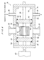
- FIGS. 1 through 3 show a trap apparatus according to a first embodiment of the present invention.
- a discharge path 14 is provided for evacuating a hermetically sealed chamber 10 constituting a part of a semiconductor fabrication apparatus by a vacuum pump 12.
- a trap apparatus 18 is provided upstream of the vacuum pump 12.
- the trap apparatus 18 comprises a trap container 26 constituting a trap chamber 24 having a suction port 20 and a discharge port 22 communicating with the discharge path 14.
- the trap apparatus 18 further comprises a regeneration container 34 constituting a regeneration chamber 32 adjacent to the trap chamber 24, and the regeneration chamber 32 has a regeneration gas introduction port 28 and a regeneration gas discharge port 30.
- a shaft 38 on which the trap unit 36 is mounted is disposed so as to pierce through both of the containers 26, 34.
- This shaft 38 is constructed so as to be reciprocated by means of an air cylinder 40 as a switching mechanism in its axial direction, thus allowing the trap unit 36 to be alternately moved between the trap chamber 24 and the regeneration chamber 32.
- the trap unit 36 comprises baffle plates 42 mounted around the shaft 38 through end plates 44.
- the shaft 38 has a passage (not shown) therein, for allowing a low-temperature fluid to pass therethrough to cool the baffle plates 42 through the end plates 44.
- the baffle plates 42 have surfaces which have been hydrophilized, for example, by coating of a fluororesin having hydrophilic ions incorporated therein. This makes the surface energy smaller than the condensation force of a liquid. Consequently, as shown in FIG. 3, the contact angle a between the surface of the baffle plate 42 and a liquid L becomes small, and hence the area of contact of the surface of the baffle plate 42 with the liquid L becomes large, and the liquid L is liable to be attached to the surface of the baffle plate 42.
- a pair of valve elements 46, 46 movable integrally with the trap unit 36 are provided on the shaft 38 at both sides of the trap unit 36 so as to sandwich the trap unit 36 therebetween, and are positioned respectively within the trap chamber 24 and the regeneration chamber 32.
- 0-rings 48 as a sealing member are mounted respectively on both sides of the valve elements 46, 46 in their peripheral edge portions.
- the O-ring 48 can be brought into pressure contact with one of partition walls 50, 50 projecting inwardly from both ends of the trap container 26 and with one of partition walls 52, 52 projected inwardly from both ends of the regeneration container 34, whereby the trap chamber 24 and the regeneration chamber 32 are sealed.
- the operation of the trap apparatus 18 having the above construction will be described below. While semiconductor devices are manufactured, switching is made so that the trap unit 36 is positioned within the trap chamber 24, and the baffle plates 42 are cooled with a coolant. This permits a specific component, such as aluminum chloride in the case of the formation of an aluminum film, contained in a discharged gas flowing into the trap chamber 24 through the discharge path 14 to be trapped as solid matter and removed from the discharged gas. At that time, since the baffle plates 42 in the trap unit 36 have been applied to the hydrophilization treatment, the surface energy is smaller than the condensation force of a liquid. Therefore, even a product such as a condensate with Si or the like, which is difficult to be trapped, can be positively adsorbed onto the surfaces of the baffle plates 42, thus improving the trap efficiency.
- a specific component such as aluminum chloride in the case of the formation of an aluminum film
- the processing is temporarily stopped, or alternatively switching is made to other discharge trap path, and then the trap unit 36 is moved into the regeneration chamber 32. Thereafter, a regeneration gas is introduced into the regeneration chamber 32 through the introduction port 28, and discharged through the discharge port 30, whereby the trap unit 36 is regenerated.
- FIGS. 4 and 5 show the trap apparatus according to the second embodiment of the present invention.
- the surfaces of the baffle plates 42 in the trap unit 36 have been subjected to water repellent treatment, for example, by coating of a fluororesin such as tetrafluoroethylene polymer, and a regeneration liquid such as warm water or a chemical liquid, and purge gas can be introduced through the introduction port 28 into the regeneration chamber 32 in a controlled manner.
- a fluororesin such as tetrafluoroethylene polymer
- a regeneration liquid such as warm water or a chemical liquid
- the water repellent treatment is applied to the surfaces of the baffle plates 42, the surface energy is suppressed, and a liquid is liable to condense. Therefore, the liquid is not spreaded on the surface of the baffle plate 42, and is easily repelled from the surface. More specifically, as shown in FIG. 5, the contact angle ⁇ between the surface of the baffle plate 42 and the liquid L becomes large, and the surface of the baffle plate 42 is brought into point contact with the liquid L, thus allowing the liquid L to be easily repelled from the surface of the baffle plate 42.
- the processing is temporarily stopped, or alternatively switching is made to other discharge trap path, and then the trap unit 36 is moved into the regeneration chamber 32. Thereafter, a regeneration liquid is introduced through the introduction port 28 into the regeneration chamber 32 to immerse the trap unit 36 in the regeneration liquid.
- a regeneration liquid is introduced through the introduction port 28 into the regeneration chamber 32 to immerse the trap unit 36 in the regeneration liquid.
- the product deposited onto the baffle plates 42 in the trap unit 36 is dissolved in the regeneration liquid, or otherwise is separated from the baffle plates 42 by the force of flow of the regeneration liquid to allow the separated product to float in the regeneration liquid.
- the regeneration liquid containing the product dissolved therein or floating therein is successively discharged through the discharge port 30.
- purge gas such as dry N 2 gas is introduced into the regeneration chamber 32 through the introduction port 28, and then discharged through the discharge port 30 to dry the trap unit 36 and the regeneration chamber 32. Thereafter, the trap unit 36 is returned into the trap chamber 24.
- the baffle plates 42 in the trap unit 36 are applied to the water repellent treatment, and hence the surface energy is suppressed to allow the liquid to easily condense. Therefore, at the time of the regeneration of the baffle plates 42 with the regeneration liquid, the regeneration liquid is easily repelled from the surfaces of the baffle plates 42, thus improving the efficiency of washing and drying, and the efficiency of regeneration.
- This embodiment is best suited for use in trapping of a product such as SiO 2 compound, which is easy to be trapped in the trap unit, but difficult to be removed from the trap unit in the step of regenerating the trap unit.
- a lowering in trap efficiency can be compensated for by forming a trap unit into a complicated shape to increase the area of contact of the baffle plates with the discharged gas.
- FIGS. 6A, 6B and 6C show trap units best suited for use in this embodiment.
- a plurality of baffle plates 42a, 42b, 42c (6 baffle plates in total in the embodiment shown in the drawing) are provided symmetrically with respect to the left and right directions.
- Trap passages 60a, 60b, 60c are provided between adjacent baffle plates and between the baffle plate and the shaft 38.
- the baffle plates 42a, 42b, 42c have concentric arc sections 62 and linearly and parallel extended flat sections 64, and each of the baffle plates 42a, 42b, 42c is provided with a discharge hole 66.
- FIG. 6B shows an embodiment in which a plurality of arc-shaped baffle plates 42a, 42b, 42c, 42d and 42e are disposed so as to surround the shaft 38, and curved trap passages 60a, 60b, 60c, 60d and 60e are constructed in a multi-layer form between the baffle plate 42a and the shaft 38, and between these baffle plates 42a, 42b, 42c, 42d and 42e.
- the width of the inlet on the upstream side of each of the passages is constructed so as to be widened at a more obtuse angle than the width of the outlet, and guide baffles 68a, 68b and 68c serving to distribute gas flowing on the central portion to the peripheral passages are provided on the inlet side.
- FIG. 6C shows an embodiment in which other baffle plates 42d, 42e are disposed only on the upstream side of a portion between the baffle plates 42a, 42a and a portion between the baffle plates 42a, 42b, shown in FIG. 6A, so that the upstream side of the passage 60a is divided into two passages 60a1, 60a2 through the baffle plate 42d and the upstream side of the passage 60b is divided into two passages 60b1, 60b2 through the baffle plate 42e.
- the present invention can improve the efficiency of trapping products or the efficiency of removing products deposited on the trap unit, i.e., the efficiency of regenerating the trap unit. Therefore, if the present invention is applied to an evacuation system for semiconductor processing apparatuses or the like, then the apparatuses can be stably operated to thus improve reliability thereof. Thus, it is possible to prolong the service life of vacuum pumps, protect devices for removing harmful substances, improve the reliability of operation through a reduction in loss time, and reduce equipment and/or operation costs.
- the invention relates to a trap apparatus disposed for evacuating a chamber through a vacuum pump, said trap apparatus comprising: a trap unit for depositing thereon a product contained in a discharged gas and removing the product.
- the invention may be summarized as follows:
Landscapes
- Chemical & Material Sciences (AREA)
- Metallurgy (AREA)
- Chemical Kinetics & Catalysis (AREA)
- Engineering & Computer Science (AREA)
- Materials Engineering (AREA)
- Mechanical Engineering (AREA)
- General Chemical & Material Sciences (AREA)
- Organic Chemistry (AREA)
- Compressors, Vaccum Pumps And Other Relevant Systems (AREA)
- Separating Particles In Gases By Inertia (AREA)
- Treating Waste Gases (AREA)
- Drying Of Semiconductors (AREA)
- Physical Vapour Deposition (AREA)
- Vaporization, Distillation, Condensation, Sublimation, And Cold Traps (AREA)
Applications Claiming Priority (2)
| Application Number | Priority Date | Filing Date | Title |
|---|---|---|---|
| JP31936499 | 1999-11-10 | ||
| JP31936499A JP2001132638A (ja) | 1999-11-10 | 1999-11-10 | トラップ装置 |
Publications (2)
| Publication Number | Publication Date |
|---|---|
| EP1099778A2 true EP1099778A2 (fr) | 2001-05-16 |
| EP1099778A3 EP1099778A3 (fr) | 2001-09-19 |
Family
ID=18109337
Family Applications (1)
| Application Number | Title | Priority Date | Filing Date |
|---|---|---|---|
| EP00124220A Withdrawn EP1099778A3 (fr) | 1999-11-10 | 2000-11-09 | Dispositif de piègeage |
Country Status (6)
| Country | Link |
|---|---|
| US (1) | US6464466B1 (fr) |
| EP (1) | EP1099778A3 (fr) |
| JP (1) | JP2001132638A (fr) |
| KR (1) | KR20010051559A (fr) |
| CN (2) | CN1194173C (fr) |
| TW (1) | TW475974B (fr) |
Families Citing this family (6)
| Publication number | Priority date | Publication date | Assignee | Title |
|---|---|---|---|---|
| JP4046474B2 (ja) * | 2000-11-13 | 2008-02-13 | 株式会社荏原製作所 | 連続処理型トラップ装置及び該トラップ装置の運転方法 |
| KR100837543B1 (ko) * | 2003-12-12 | 2008-06-12 | 동부일렉트로닉스 주식회사 | 펌프배기라인의 냉각 트랩장치 및 이를 이용한 파우더제거방법 |
| GB0416385D0 (en) * | 2004-07-22 | 2004-08-25 | Boc Group Plc | Gas abatement |
| KR100621660B1 (ko) * | 2005-07-01 | 2006-09-11 | 주식회사 뉴프로텍 | 반도체 부산물 트랩장치 |
| JP6150716B2 (ja) * | 2013-12-02 | 2017-06-21 | 住友重機械工業株式会社 | コールドトラップ |
| JP7453890B2 (ja) * | 2020-10-05 | 2024-03-21 | 株式会社神戸製鋼所 | 再生装置、ガス処理装置、再生方法及びガス処理方法 |
Family Cites Families (20)
| Publication number | Priority date | Publication date | Assignee | Title |
|---|---|---|---|---|
| DE3125335A1 (de) * | 1981-06-27 | 1983-01-13 | Alfred Prof. Dr. 4400 Münster Benninghoven | Verfahren zur analyse von gasen und fluessigkeiten |
| JPS58106186A (ja) | 1981-12-18 | 1983-06-24 | Hitachi Ltd | トラツプ装置 |
| US5053244A (en) * | 1987-02-21 | 1991-10-01 | Leybold Aktiengesellschaft | Process for depositing silicon oxide on a substrate |
| AU611244B2 (en) * | 1987-12-25 | 1991-06-06 | Terumo Kabushiki Kaisha | Medical instrument |
| US5443727A (en) * | 1990-10-30 | 1995-08-22 | Minnesota Mining And Manufacturing Company | Articles having a polymeric shell and method for preparing same |
| JPH06188108A (ja) | 1992-12-21 | 1994-07-08 | Canon Inc | 薄膜抵抗器の製造方法、成膜装置用防着板及び成膜装置 |
| EP0648861A1 (fr) | 1993-10-15 | 1995-04-19 | Applied Materials, Inc. | Appareillage de traitement des semi-conducteurs |
| JPH07238181A (ja) * | 1994-01-21 | 1995-09-12 | Minnesota Mining & Mfg Co <3M> | 親水化多孔性物品 |
| US5972183A (en) | 1994-10-31 | 1999-10-26 | Saes Getter S.P.A | Getter pump module and system |
| US6187072B1 (en) * | 1995-09-25 | 2001-02-13 | Applied Materials, Inc. | Method and apparatus for reducing perfluorocompound gases from substrate processing equipment emissions |
| US6045618A (en) * | 1995-09-25 | 2000-04-04 | Applied Materials, Inc. | Microwave apparatus for in-situ vacuum line cleaning for substrate processing equipment |
| US6193802B1 (en) | 1995-09-25 | 2001-02-27 | Applied Materials, Inc. | Parallel plate apparatus for in-situ vacuum line cleaning for substrate processing equipment |
| JP3544604B2 (ja) | 1996-12-16 | 2004-07-21 | 株式会社荏原製作所 | 切替式トラップ装置 |
| US6051053A (en) | 1996-12-16 | 2000-04-18 | Ebara Corporation | Trapping device and method of operation therefor |
| JP3630518B2 (ja) * | 1997-01-17 | 2005-03-16 | 株式会社荏原製作所 | トラップ装置 |
| US6152905A (en) * | 1997-10-10 | 2000-11-28 | The Procter & Gamble Company | Absorbent interlabial device comprising a fluid acquisition/transfer complex |
| JP3708322B2 (ja) | 1998-02-16 | 2005-10-19 | 株式会社荏原製作所 | トラップシステム |
| US6368371B1 (en) | 1998-01-22 | 2002-04-09 | Ebara Corporation | Trap device and trap system |
| US6007330A (en) * | 1998-03-12 | 1999-12-28 | Cosmos Factory, Inc. | Liquid precursor delivery system |
| US6197119B1 (en) * | 1999-02-18 | 2001-03-06 | Mks Instruments, Inc. | Method and apparatus for controlling polymerized teos build-up in vacuum pump lines |
-
1999
- 1999-11-10 JP JP31936499A patent/JP2001132638A/ja active Pending
-
2000
- 2000-11-07 US US09/706,694 patent/US6464466B1/en not_active Expired - Fee Related
- 2000-11-08 TW TW089123541A patent/TW475974B/zh not_active IP Right Cessation
- 2000-11-09 EP EP00124220A patent/EP1099778A3/fr not_active Withdrawn
- 2000-11-09 KR KR1020000066368A patent/KR20010051559A/ko not_active Abandoned
- 2000-11-10 CN CNB001326252A patent/CN1194173C/zh not_active Expired - Fee Related
- 2000-11-10 CN CNA2005100530507A patent/CN1769684A/zh active Pending
Also Published As
| Publication number | Publication date |
|---|---|
| CN1769684A (zh) | 2006-05-10 |
| CN1194173C (zh) | 2005-03-23 |
| JP2001132638A (ja) | 2001-05-18 |
| EP1099778A3 (fr) | 2001-09-19 |
| KR20010051559A (ko) | 2001-06-25 |
| CN1296127A (zh) | 2001-05-23 |
| TW475974B (en) | 2002-02-11 |
| US6464466B1 (en) | 2002-10-15 |
Similar Documents
| Publication | Publication Date | Title |
|---|---|---|
| JP4732750B2 (ja) | 真空排気装置 | |
| TWI388729B (zh) | 用於真空泵浦之前級預處理 | |
| EP0847789B1 (fr) | Dispositif de piégeage | |
| CN104066989B (zh) | 用于排空腔室并净化从所述腔室抽取的气体的装置和方法 | |
| US6464466B1 (en) | Trap apparatus | |
| JPH0339198B2 (fr) | ||
| EP0847790B1 (fr) | Procédé de mise en oeuvre un dispositif de piégeage | |
| US6368371B1 (en) | Trap device and trap system | |
| JP3979458B2 (ja) | トラップ装置 | |
| JP3617575B2 (ja) | 真空排気システム | |
| JP3129980B2 (ja) | トラップ装置及びその再生方法 | |
| JP3188235B2 (ja) | トラップ装置 | |
| JP3433998B2 (ja) | 濾過装置及びそれによる真空ポンプ系保護方法 | |
| JP2001107858A (ja) | トラップ装置 | |
| JP3630518B2 (ja) | トラップ装置 | |
| JP2002110660A (ja) | 半導体製造装置 | |
| JP2001342950A (ja) | 真空ドライポンプ及びトラップ方法 |
Legal Events
| Date | Code | Title | Description |
|---|---|---|---|
| PUAI | Public reference made under article 153(3) epc to a published international application that has entered the european phase |
Free format text: ORIGINAL CODE: 0009012 |
|
| AK | Designated contracting states |
Kind code of ref document: A2 Designated state(s): AT BE CH CY DE DK ES FI FR GB GR IE IT LI LU MC NL PT SE TR Kind code of ref document: A2 Designated state(s): DE FR GB |
|
| AX | Request for extension of the european patent |
Free format text: AL;LT;LV;MK;RO;SI |
|
| PUAL | Search report despatched |
Free format text: ORIGINAL CODE: 0009013 |
|
| AK | Designated contracting states |
Kind code of ref document: A3 Designated state(s): AT BE CH CY DE DK ES FI FR GB GR IE IT LI LU MC NL PT SE TR |
|
| AX | Request for extension of the european patent |
Free format text: AL;LT;LV;MK;RO;SI |
|
| 17P | Request for examination filed |
Effective date: 20020319 |
|
| AKX | Designation fees paid |
Free format text: DE FR GB |
|
| STAA | Information on the status of an ep patent application or granted ep patent |
Free format text: STATUS: THE APPLICATION HAS BEEN WITHDRAWN |
|
| 18W | Application withdrawn |
Effective date: 20070810 |