EP1099809A2 - Caveau funéraire - Google Patents
Caveau funéraire Download PDFInfo
- Publication number
- EP1099809A2 EP1099809A2 EP00124145A EP00124145A EP1099809A2 EP 1099809 A2 EP1099809 A2 EP 1099809A2 EP 00124145 A EP00124145 A EP 00124145A EP 00124145 A EP00124145 A EP 00124145A EP 1099809 A2 EP1099809 A2 EP 1099809A2
- Authority
- EP
- European Patent Office
- Prior art keywords
- trough
- sleeve
- hole
- floor pan
- peripheral walls
- Prior art date
- Legal status (The legal status is an assumption and is not a legal conclusion. Google has not performed a legal analysis and makes no representation as to the accuracy of the status listed.)
- Withdrawn
Links
- 238000009933 burial Methods 0.000 title claims description 71
- 230000002093 peripheral effect Effects 0.000 claims description 45
- 238000007789 sealing Methods 0.000 claims description 33
- 239000000463 material Substances 0.000 claims description 21
- XLYOFNOQVPJJNP-UHFFFAOYSA-N water Substances O XLYOFNOQVPJJNP-UHFFFAOYSA-N 0.000 claims description 18
- 238000004519 manufacturing process Methods 0.000 claims description 12
- 230000008878 coupling Effects 0.000 claims description 6
- 238000010168 coupling process Methods 0.000 claims description 6
- 238000005859 coupling reaction Methods 0.000 claims description 6
- 150000001875 compounds Chemical class 0.000 claims description 5
- 239000004567 concrete Substances 0.000 claims description 4
- 230000000630 rising effect Effects 0.000 claims description 3
- 239000007789 gas Substances 0.000 description 14
- 239000002689 soil Substances 0.000 description 7
- 238000000354 decomposition reaction Methods 0.000 description 4
- 239000007788 liquid Substances 0.000 description 4
- 239000000565 sealant Substances 0.000 description 4
- 230000000712 assembly Effects 0.000 description 3
- 238000000429 assembly Methods 0.000 description 3
- 238000000034 method Methods 0.000 description 3
- 230000004048 modification Effects 0.000 description 3
- 238000012986 modification Methods 0.000 description 3
- 230000008569 process Effects 0.000 description 3
- OKTJSMMVPCPJKN-UHFFFAOYSA-N Carbon Chemical compound [C] OKTJSMMVPCPJKN-UHFFFAOYSA-N 0.000 description 2
- 238000013461 design Methods 0.000 description 2
- 230000000694 effects Effects 0.000 description 2
- 230000002349 favourable effect Effects 0.000 description 2
- 238000003780 insertion Methods 0.000 description 2
- 230000037431 insertion Effects 0.000 description 2
- 239000011178 precast concrete Substances 0.000 description 2
- 244000025254 Cannabis sativa Species 0.000 description 1
- 229910000831 Steel Inorganic materials 0.000 description 1
- 208000027418 Wounds and injury Diseases 0.000 description 1
- 239000000853 adhesive Substances 0.000 description 1
- 230000001070 adhesive effect Effects 0.000 description 1
- 241001148470 aerobic bacillus Species 0.000 description 1
- 238000006065 biodegradation reaction Methods 0.000 description 1
- 210000000988 bone and bone Anatomy 0.000 description 1
- 230000008859 change Effects 0.000 description 1
- 239000004927 clay Substances 0.000 description 1
- 238000004140 cleaning Methods 0.000 description 1
- 238000010276 construction Methods 0.000 description 1
- 230000006378 damage Effects 0.000 description 1
- 239000000835 fiber Substances 0.000 description 1
- 239000003673 groundwater Substances 0.000 description 1
- 208000014674 injury Diseases 0.000 description 1
- 238000009434 installation Methods 0.000 description 1
- 239000003621 irrigation water Substances 0.000 description 1
- 239000000203 mixture Substances 0.000 description 1
- 230000003647 oxidation Effects 0.000 description 1
- 238000007254 oxidation reaction Methods 0.000 description 1
- 230000035515 penetration Effects 0.000 description 1
- 238000004382 potting Methods 0.000 description 1
- 239000010959 steel Substances 0.000 description 1
- 238000012549 training Methods 0.000 description 1
- 238000009423 ventilation Methods 0.000 description 1
Images



Classifications
-
- E—FIXED CONSTRUCTIONS
- E04—BUILDING
- E04H—BUILDINGS OR LIKE STRUCTURES FOR PARTICULAR PURPOSES; SWIMMING OR SPLASH BATHS OR POOLS; MASTS; FENCING; TENTS OR CANOPIES, IN GENERAL
- E04H13/00—Monuments; Tombs; Burial vaults; Columbaria
- E04H13/005—Ventilation systems therefor
Definitions
- Grave chambers made of precast concrete used. This can be refilled after the decomposition has been completed, if the leg remains of the previous occupancy on one suitable place, for example in a bone chamber, have been filed.
- These burial chambers made of precast concrete are available in different versions roughly divide into open burial chambers and closed burial chambers can.
- An open burial chamber is from DE 35 37 367.9 A1 known. It has several chamber rings in one Pit to be stacked on top of each other by being circulating Heels on both the top and bottom of the chamber rings be led among themselves. At the bottom there is a base plate on which the chamber rings are loose are put on. On the top chamber ring there are ceiling panels hung up after the interior of the burial chambers complete at the top. These ceiling tiles are about 60 cm below ground level. The space becomes earth, especially with topsoil, filled up to earth level. This earth cover of the burial chamber encloses a gas lock, on a passage opening in one of the ceiling panels is put on. After a funeral is in the Gas lock inserted a filter cartridge with activated carbon, which is supposed to bind the putrefaction gases, if appropriate Pressure conditions a gas exchange from the inside to the outside takes place.
- This open burial chamber can only be used in soil and water conditions are used where penetration and Water is not expected to accumulate in the burial chamber.
- the ground With each burial, the ground must be above the ceiling tiles removed and the ceiling panels are removed. After burial you must first do it in reverse order put the ceiling tiles back on and after inserting them or replace the filter cartridge in the gas lock the earth cover is put back on the ceiling slab become. In addition, the entire grass planting must later to be renewed.
- One of the embodiments has a closed floor pan. As a cover serves a trough that is placed on the walls of the floor pan becomes. There is a seal between the floor pan and the trough. There is an earth cover in the trough, which is below other grave planting.
- the gas exchange between the interior of the burial chamber and its surroundings through a gas exchange line that has a through hole in the Has bottom of the trough to which a gas lock is connected is. From the gas lock, the exiting Gases distributed in the earth cover, which in doing so Biofilter works.
- the earth cover remains in the trough and therefore also an existing grave plantation. So this must be done after a Burial will not be renewed. So that the trough in front of one Burial easily taken off and after burial can be put back on, there are retaining walls, which the burial chamber at the height of the trough at a short distance surrounded outside. Depending on whether these burial chambers in Individual arrangement or in group arrangement, especially in Row arrangement next to each other, have the Retaining walls a different embodiment.
- the invention is based on the object of a burial chamber to create the benefits of a closed burial chamber can be achieved with lower manufacturing costs than at the well-known burial chamber. This task is accomplished by a Grave chamber solved with the features specified in claim 1.
- the trough can be hung in the floor pan, with its cantilever edge on the peripheral walls of the Floor pan rests.
- the trough can be just as light and simple be lifted out of the floor pan for burial.
- the earth cover can be used together with any Planting remains in the trough.
- the mouth of the air exchange line is located at a sufficient depth below the surface of the Soil material with which the environment of the burial chamber to about is filled up at the top of the trough.
- This Soil material is used for the biodegradation of the decomposition gases, at the mouth of the air exchange line to the outside emerge.
- a drainage pipe for the trough is on the one hand at a through hole of the Troges, especially on the bottom, and on the other an outlet opening in one of the peripheral walls or in Bottom of the floor pan is connected, that from the trough ingested rainwater or meltwater or even excess Irrigation water can be drained to the outside, so that it does not accumulate in the trough.
- a desired residual moisture in the trough can be obtained by using the through hole for the drainage pipe or the inlet opening the drainage line itself in a corresponding Distance is arranged above the bottom of the trough.
- the grave chamber looks pleasing.
- the usually prefabricated seal more easily be positioned around the peripheral walls of the floor pan.
- the through hole in the peripheral wall for the Air exchange line a smooth inner surface with proportionate has narrow diameter tolerances, so that Connecting the air exchange line is facilitated. Because at least one circumferential groove in the sleeve with a sealing ring, the air exchange line after inserting into the sleeve at the same time sealed. If two circumferential grooves and therefore two If there are sealing rings, the plug is inserted into the sleeve Part of the air exchange line at the same time Alignment line of the axis of the sleeve is maintained and also double sealed.
- the sleeve can be used in the manufacture of the Floor pan can be embedded in their material. She could also be inserted into the through hole later and potted with a sealant. Also at a sleeve embedded in the manufacturing process can Add a sealant to ensure the tightness of the seat Improve the sleeve in the peripheral wall even further.
- the burial chambers according to claim 7 ensures that the drainage line is not through Parts of the earth cover in the trough are blocked.
- the drainage hose due to the mounting hole in the vicinity of the through hole for the drainage pipe the drainage hose also afterwards, that is after the complete one Hang the trough in the floor pan, on the floor the trough and / or connected to the peripheral wall of the floor pan become.
- Access to the drainage hose is easy when installing the burial chamber for the first time possible if there is no earth cover in the trough. Even if such an earth cover is already in the trough has been filled in, the earth cover only needs to be in the Area of the opening of the month to be removed so her Lid can be lifted off and the connection of the drainage hose made with the two parts of the burial chamber or vice versa can be solved again.
- the burial chamber according to claim 9 ensures that even when very unfavorable Water from outside into the interior of the burial chamber should have penetrated, this through the check valve can flow off again. Conversely, outside rising water not through the float valve in the Enter the interior of the burial chamber.
- the burial chambers according to claim 10 can - similar to the use of a check valve the locking body the through hole in the bottom of the If necessary, the floor pan is opened and then closed again around something that has penetrated from somewhere To drain water from the burial chamber.
- the closure body On the coupling element can the closure body with a tool be recorded and operated.
- the closure body With further training after Claim 11 is sufficient, the closure body only so far pull out the sleeve that the through holes in its collar above the upper sealing ring of the sleeve stand. The part of the collar remaining in the sleeve facilitates pushing the closure body back into the Closed position.
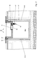
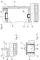
- the burial chamber which can be seen in particular from FIGS. 1 and 2 30 has a trough-shaped as main assemblies Base body 31 and a cover in the form of a trough 32 on.
- the trough-shaped body is briefly referred to as Floor pan 31 called.
- the floor pan 31 is by a floor 33 and by four Sidewalls or peripheral walls 34 formed, the gas and connect waterproof to each other. If necessary, follow the four peripheral walls 34 by additional digits of distinguished each other.
- a circumferential channel 36 (FIG. 4), in which is an annular sealing strip 37 is inserted.
- the trough 32 is through a bottom 38 and through four side walls or circumferential walls 39 formed, which are gastight and watertight connect to each other. Again, if necessary the peripheral walls 39 are distinguished from one another by additional digits.
- the peripheral walls 39 of the trough 32 have a plan that within the outline of the peripheral walls 34 of the floor pan 31 is located.
- the cantilever edge 41 covers the floor plan area of the peripheral walls 34 of the floor pan 31. Conveniently the outside of the cantilever edge 41 is flush with the outside of the peripheral walls 34 of the floor pan 31.
- the floor pan 31 and the trough 32 are made of concrete, and preferably made of steel fiber concrete.
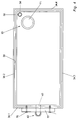
- the burial chamber 30 is equipped with an air exchange line 42 (Fig. 1, 3 and 4)
- a through hole 43 available. This is as far as possible above the Bottom 33 arranged.
- the through hole 43 is provided with a sleeve 43. This is made of plastic. Their length is at least approximately equal to the wall thickness of the peripheral wall 34.1.
- the Sleeve 44 has two circumferential on its inside Grooves 45, in each of which a sealing ring 46 in the form of a Round cord ring is used. Because of these two sealing rings 46 the sleeve 44 is also used as a double sleeve designated.
- the sleeve 43 is used in the manufacture of the floor pan 31 embedded in their material. Because of through the grooves 45 formed circumferential bulges on the The outside of the sleeve 44 has this in the material of the peripheral wall 34.1 sufficient liability. If it is anyway sleeve 44 may appear desirable or necessary additionally with a sealing compound against the peripheral wall 34.1 are sealed.
- the sleeve 44 To the through hole 43, strictly speaking to the sleeve 44, connects the actual air exchange line 42. This has a pipe bend of at least approximately 90 °.
- the Leg with the smooth pipe section is in the sleeve 44 inserted where it is held by the two sealing rings 46 and sealed at the same time.
- the other Leg is designed at the end as a pipe sleeve into which a Sealing ring is used.
- this pipe socket is a straight pipe section used.
- a check valve 49 in the form of a float valve connected to the outside rising water closes the air exchange line 42 and so prevents water from entering the interior of the burial chamber 30 penetrates.
- the parts of the air exchange line 42, namely the elbow 47, the pipe section 48 and that Check valve 49, are additionally by means of an adhesive permanently connected. This is to ensure that when filling the area around the burial chamber the parts of the air exchange line 42 from each other be separated.
- the air exchange line 42 extends from the through hole 43 from downwards, as can be seen from FIG. 3. A slight inclination can also be allowed become. It is important that the mouth of the air exchange line 42 is so deep that the height of the Air exchange line enveloping filling material and that sufficient material down to the earth's surface biological cleaning effect in relation to the Has putrefaction gases emerging from the air exchange line, if the air pressure is outside due to fluctuations in air pressure the burial chamber 30 lower than the air pressure inside the burial chamber is.
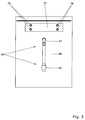
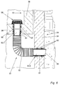
- the burial chamber 30 with a drainage line 51 (Fig. 1, 6 and 7) equipped so the rain and meltwater collected by the trough, but even excess water in the trough 32 is not up to damming its upper edge but flowing outwards can.
- the drainage line 51 has a flexible Hose 52 on which at each of its ends with a Hose nozzle 52 is permanently and tightly connected.
- the Hose 52 can be a smooth hose, a corrugated hose or be designed as a spiral hose. As a corrugated hose and it is generally easier to use as a spiral hose bend and also change in length within certain limits.
- the hose nozzles 53 are sections of a rigid cylindrical Plastic tube.
- the drainage line 51 includes on one side Through hole 54 in the bottom 38 of the tube 32 and on the other hand to a through hole 55 in the peripheral wall 34 of the floor pan 31 at.
- a double sleeve 56 is arranged, the has a length which is equal to the wall thickness of the base 38, and in the manufacture of the trough 32 in its material is embedded.
- the double sleeve 56 has two circumferential Grooves, in each of which a sealing ring 57 in the form a round cord ring is used.
- Hose nozzle 53.1 of hose 52 is only up to about the middle of the double sleeve 56 inserted into this, so that it only cooperates with the lower sealing ring 57 and is held by this by friction.
- a sieve 58 is inserted in the upper part of the double sleeve 56, such as the drainage pipes from Flat roofs is common.
- a double sleeve is also embedded in its material. It also has two sealing rings 62.
- the interacting hose sleeve 53.2 of hose 52 is so long that it emerges from the double sleeve 61 protrudes a certain distance so that what emerges from it Water not on the outside of the peripheral wall 34 runs down, but directly into the circumferential trough 34 surrounding filling material passes over and derived from this becomes.
- the mounting opening 31 is provided with a double sleeve 66, which is embedded in the material of the bottom 38. She points two sealing rings 67.
- the sleeve 66 is arranged that it is flush with the bottom 68 of the bottom and overhangs the top 69 to a certain extent.
- the Assembly opening 65 is closed by a cover 71, which has a hollow cylindrical collar 72, matched to the double sleeve 66 and its sealing rings 67 is.
- the lid 71 has an outer diameter of is larger than the outer diameter of the double sleeve 66. The excess should be so large that the lid 71 is comfortable can be grasped with the hands and lifted out can.
- the protrusion of the double sleeve should also be on top of this the top 69 of the bottom 38 can be matched.
- the assembly opening 65 is expediently chosen so large that through it the drainage line 51, in particular whose hose 52 can be easily reached by hand
- the floor pan 81 shown in detail in FIG. 8 has a check valve 83 in the shape of its bottom 82 a float valve on how it is similar in the air exchange line 42 (Fig. 5) is used.
- the check valve 83 is either, as shown, in the material of the bottom 82 embedded, or it is in a not shown Housing used waterproof, which in turn in the material of the bottom 82 is embedded and / or by means of a sealant is sealed with it.
- the check valve 83 is advantageously with a Provide collar 84, if not already one the design of the check valve 83 is present.
- This Collar 84 protrudes over the top 85 of the bottom 82 so high out, so high a liquid level in the burial chamber 80 is desired so that in the burial chamber 80 always one for the Decaying processes in the burial chamber have sufficient humidity is guaranteed.
- the through hole with the double sleeve 94 and the cover 95 is expedient in the floor plan area of the assembly opening 65 arranged in the trough 92, so that the closure body 95 can be operated from there.
- FIG. 10 shows a special embodiment of the closure body 95 can be seen. With him are in the hollow cylindrical Collar 97 radially aligned through holes present in a normal to the longitudinal axis of the closure body 95 aligned plane are arranged in axial direction between the two sealing rings Double sleeve 94 is located. It is useful if this Through holes 98 near the top seal ring of FIG Double sleeve 97 are located.
Landscapes
- Engineering & Computer Science (AREA)
- Architecture (AREA)
- Civil Engineering (AREA)
- Structural Engineering (AREA)
- Sink And Installation For Waste Water (AREA)
Applications Claiming Priority (2)
| Application Number | Priority Date | Filing Date | Title |
|---|---|---|---|
| DE1999153740 DE19953740B4 (de) | 1999-11-09 | 1999-11-09 | Grabkammer |
| DE19953740 | 1999-11-09 |
Publications (2)
| Publication Number | Publication Date |
|---|---|
| EP1099809A2 true EP1099809A2 (fr) | 2001-05-16 |
| EP1099809A3 EP1099809A3 (fr) | 2003-01-15 |
Family
ID=7928338
Family Applications (1)
| Application Number | Title | Priority Date | Filing Date |
|---|---|---|---|
| EP00124145A Withdrawn EP1099809A3 (fr) | 1999-11-09 | 2000-11-07 | Caveau funéraire |
Country Status (2)
| Country | Link |
|---|---|
| EP (1) | EP1099809A3 (fr) |
| DE (1) | DE19953740B4 (fr) |
Cited By (1)
| Publication number | Priority date | Publication date | Assignee | Title |
|---|---|---|---|---|
| CN1827986B (zh) * | 2006-01-26 | 2010-05-12 | 吴晓鸣 | 全封闭集中式安葬墓 |
Families Citing this family (3)
| Publication number | Priority date | Publication date | Assignee | Title |
|---|---|---|---|---|
| DE102008031866A1 (de) | 2008-07-05 | 2010-01-07 | Ackermann, Peter | Grabkammer |
| DE102008031869A1 (de) | 2008-07-05 | 2010-01-07 | Werner Frey | Grabkammer |
| DE102008031867A1 (de) | 2008-07-05 | 2010-01-07 | Ackermann, Peter | Grabkammer |
Citations (2)
| Publication number | Priority date | Publication date | Assignee | Title |
|---|---|---|---|---|
| DE3537367A1 (de) | 1985-10-21 | 1987-04-23 | Gerhard Suckfuell | Grabkammer |
| DE4118408A1 (de) | 1991-06-05 | 1992-12-10 | Guenther Ackermann | Grabkammer |
Family Cites Families (5)
| Publication number | Priority date | Publication date | Assignee | Title |
|---|---|---|---|---|
| DE3035578A1 (de) * | 1980-09-20 | 1982-04-08 | Lambert 5401 Dieblich Schäfer | Umweltfreundlichere und humanere bestattung |
| DE19613380C1 (de) * | 1996-04-03 | 1997-05-15 | Reinhard Martin | Belüftungssystem für eine Grabkammer |
| DE29609187U1 (de) * | 1996-05-22 | 1996-08-14 | Suckfüll, Gerhard, 97618 Niederlauer | Grabkammer |
| DE29813992U1 (de) * | 1998-08-05 | 1998-10-29 | Aschenbrenner, Harald, 66646 Marpingen | Wiederverwendbare Grabkammer |
| DE29820298U1 (de) * | 1998-11-16 | 1999-03-18 | Lammering, Thomas, Dipl.-Ing., 33335 Gütersloh | Grabkammersystemlösung |
-
1999
- 1999-11-09 DE DE1999153740 patent/DE19953740B4/de not_active Expired - Fee Related
-
2000
- 2000-11-07 EP EP00124145A patent/EP1099809A3/fr not_active Withdrawn
Patent Citations (2)
| Publication number | Priority date | Publication date | Assignee | Title |
|---|---|---|---|---|
| DE3537367A1 (de) | 1985-10-21 | 1987-04-23 | Gerhard Suckfuell | Grabkammer |
| DE4118408A1 (de) | 1991-06-05 | 1992-12-10 | Guenther Ackermann | Grabkammer |
Cited By (1)
| Publication number | Priority date | Publication date | Assignee | Title |
|---|---|---|---|---|
| CN1827986B (zh) * | 2006-01-26 | 2010-05-12 | 吴晓鸣 | 全封闭集中式安葬墓 |
Also Published As
| Publication number | Publication date |
|---|---|
| EP1099809A3 (fr) | 2003-01-15 |
| DE19953740A1 (de) | 2001-05-10 |
| DE19953740B4 (de) | 2007-12-06 |
Similar Documents
| Publication | Publication Date | Title |
|---|---|---|
| DE60101374T2 (de) | Behälter für die Kultivierung von Pflanzen | |
| EP0699255B1 (fr) | Construction prefabriquee en beton arme ou dans un materiau equivalent | |
| EP1099809A2 (fr) | Caveau funéraire | |
| DE102009053027A1 (de) | Regenwasser-Sicker/Rückhalte-System | |
| DE3934633C1 (en) | Collector for rain water - tank sealed at bottom and mounted coaxially in drainage pit | |
| DE60022526T2 (de) | Modularer dränageblock | |
| DE202008017195U1 (de) | Bewässerungsvorrichtung für Pflanzen und Steuervorrichtung für ein derartiges Bewässerungssystem | |
| DE9206685U1 (de) | Wasserspeicherbehälter | |
| DE3534327C1 (en) | Prefabricated container forming coffin-receiving vault - comprises GRP trough and lid with perimeter holes allowing air circulation | |
| DE29923727U1 (de) | Grabkammer | |
| DE19655160C2 (de) | Bodenfilter für Regen- und Abwasser mit Verschlußeinrichtung | |
| DE19610743C2 (de) | Bodenfilter für Regen- und Abwasser | |
| DE29715802U1 (de) | Schluckbrunnen | |
| EP1245537B1 (fr) | Station d'épuration d' eau polluée avec une couche à plantes | |
| DE4118408A1 (de) | Grabkammer | |
| EP1653012A2 (fr) | Installation d'infiltration | |
| EP0808966B1 (fr) | Caveau funéraire | |
| DE9109653U1 (de) | Grabkammer | |
| DE20117974U1 (de) | Regenwasserspeicher | |
| DE102006038664B4 (de) | Schacht-Unterteil | |
| EP0372535B1 (fr) | Procéde pour la construction d'un point de mesure des eaux souterraines et dispositif pour l'exécution de ce procéde | |
| DE4443983C2 (de) | Schachtanordnung | |
| DE9108485U1 (de) | Grabkammer | |
| EP0528124B1 (fr) | Caveau funéraire | |
| DE9311682U1 (de) | Grabkammer |
Legal Events
| Date | Code | Title | Description |
|---|---|---|---|
| PUAI | Public reference made under article 153(3) epc to a published international application that has entered the european phase |
Free format text: ORIGINAL CODE: 0009012 |
|
| AK | Designated contracting states |
Kind code of ref document: A2 Designated state(s): AT BE CH CY DE DK ES FI FR GB GR IE IT LI LU MC NL PT SE TR |
|
| AX | Request for extension of the european patent |
Free format text: AL;LT;LV;MK;RO;SI |
|
| PUAL | Search report despatched |
Free format text: ORIGINAL CODE: 0009013 |
|
| AK | Designated contracting states |
Kind code of ref document: A3 Designated state(s): AT BE CH CY DE DK ES FI FR GB GR IE IT LI LU MC NL PT SE TR |
|
| AX | Request for extension of the european patent |
Free format text: AL;LT;LV;MK;RO;SI |
|
| AKX | Designation fees paid |
Designated state(s): AT BE CH CY DE DK ES FI FR GB GR IE IT LI LU MC NL PT SE TR |
|
| STAA | Information on the status of an ep patent application or granted ep patent |
Free format text: STATUS: THE APPLICATION IS DEEMED TO BE WITHDRAWN |
|
| 18D | Application deemed to be withdrawn |
Effective date: 20030603 |