EP1100314B2 - Vorrichtung zum automatischen melken von tieren - Google Patents
Vorrichtung zum automatischen melken von tieren Download PDFInfo
- Publication number
- EP1100314B2 EP1100314B2 EP99943530A EP99943530A EP1100314B2 EP 1100314 B2 EP1100314 B2 EP 1100314B2 EP 99943530 A EP99943530 A EP 99943530A EP 99943530 A EP99943530 A EP 99943530A EP 1100314 B2 EP1100314 B2 EP 1100314B2
- Authority
- EP
- European Patent Office
- Prior art keywords
- teatcup
- teatcups
- teat
- movable arm
- end portion
- Prior art date
- Legal status (The legal status is an assumption and is not a legal conclusion. Google has not performed a legal analysis and makes no representation as to the accuracy of the status listed.)
- Expired - Lifetime
Links
- 210000002445 nipple Anatomy 0.000 description 43
- 210000000481 breast Anatomy 0.000 description 6
- 210000001015 abdomen Anatomy 0.000 description 2
- 238000004140 cleaning Methods 0.000 description 1
- 239000008267 milk Substances 0.000 description 1
- 210000004080 milk Anatomy 0.000 description 1
- 235000013336 milk Nutrition 0.000 description 1
Images



Classifications
-
- A—HUMAN NECESSITIES
- A01—AGRICULTURE; FORESTRY; ANIMAL HUSBANDRY; HUNTING; TRAPPING; FISHING
- A01J—MANUFACTURE OF DAIRY PRODUCTS
- A01J5/00—Milking machines or devices
- A01J5/017—Automatic attaching or detaching of clusters
- A01J5/0175—Attaching of clusters
Definitions
- the present invention relates to an apparatus for automatically milking an animal, comprising a plurality ofteatcups each having a teat entrance end, and a movable arm for moving said teatcups towards a teat of an animal to be milked and attaching it thereto.
- FIG. 5C discloses in one embodiment (Fig. 5C) an apparatus for automatic milking which holds a magazine or clip of four teatcups, which is manoeuvred so as to place one of the teatcups below the intended cow teat, whereupon a dedicated lifting device is actuated, lifting the individual teatcup until suction attaches it to its teat.
- An object of the invention is to improve the success rate of teatcup attachment and make possible, with very simple and reliable means, reattachment of inadvertently detached teatcups, without the necessity of removing any other teatcups first.
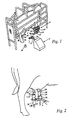
- FIG. 1 shows robot milking stall 2 provided with a milking robot 4 having a movable arm in form of a robot arm 6 with a gripping means 7 adapted to grip one teatcup.
- a teatcup rack 8 is provided with four teatcups 10, 12, 14, 16, each teatcup having a teat entrance end 17a and a milk exit end 17b.
- two teatcups 10, 12 thereof are of the same or similar length, while two other teatcups 14, 16 - of the same or similar length - are shorter than the other two teatcups 10, 12.
- An udder 18 of a cow has rear teats 20, 22, and front teats 24, 26.
- the robot arm shown in figure 1 is intended to bring the teatcups 10, 12, 14, 16 under the belly and between the front and rear legs of a cow.
- the teatcups 10, 12 are to be attached to the rear teats 20, 22, whereas the teatcups 14, 16 are to be attached to the front teats 24, 26, for reasons that will be apparent below.
- An image capturing device 28 such as a digital video camera is arranged on the side of the stall 2, for viewing at least the udder 18 of the cow, before, during and/or after teatcup attachment.
- the robot arm 6 is provided with an angular end portion 30, which is provided with a teat location means 32, in the form of a digital video camera and/or a laser sensor, and the gripping means 7. This allows for a movement of a teatcup towards the rear of the cow, while viewing in the same direction.
- the angular end portion may be e.g. perpendicular
- one of the longer teatcups 10 is attached to a rear teat 20. Then, the other one of the longer teatcups 12 is attached to the other rear teat 22. Subsequently, one of the two shorter teatcups 14 is attached to a front teat 24. Thereafter the other one of the shorter teatcups 16 is attached to the other front teat 26.
- one of the longer teatcups 10 is attached to a rear teat 20. Then, one of the two shorter teatcups 14 is attached to a front teat 24. Then, the other one of the longer teatcups 12 is attached to the other rear teat 22 and thereafter the other one of the shorter teatcups 16 is attached to the other front teat 26.
- Figure 2 shows a situation where one of the longer teatcups 10 for some reason has fallen off one of the rear teats e.g. 20 and therefore (or for any other reason) has to be re-attached thereonto, while a shorter teatcup e.g. 14 is still attached to a front teat 24 in front of that rear teat 20.
- the longer teatcup is allowed to be re-attached to the rear teat 20 without having to first detach the teatcup 14, as the teat robot arm end portion 30 will be able to pass the short teatcup 14.
- the robot arm 6 should be adapted to move each teatcup between the rear legs of the cow.
- Such a robot arm 6 should preferably be straight, rather than having an angular end portion 30.
- the longer teatcups 10, 12 are in that case to be attached to the front teats 24, 26 and the shorter teatcups 14, 16 to the rear teats 20, 22.
- a further image capturing device 28 may be arranged on the opposite side of the stall 2 for viewing at least the udder 18 from that side.
- FIG 3A illustrates a second arrangement, in which the teatcup rack 8 in figure 1 is substituted by a teatcup supply means 40 hingedly arranged on the robot arm 6.
- the teatcup supply means 40 constituting said movable arm is allowed to rotate about the hinge by means of a pneumatic or hydraulic cylinder 41.
- the teatcup supply means 40 is provided with a pair of parallel elongated members 42, 44, defining an intermediate elongated space 46.
- the members 42, 44 and the space 46 have a fork like configuration, i.e. the elongated space 46 has an open end 47.
- the cylinder 41 may be substituted by an electric step motor.
- the members 42, 44 are furthermore formed to comprise a lower portion 48, an upper portion 49 and an intermediate portion 50.
- the upper portion 49 is adapted to house one teatcup 52
- the lower portion 48 is adapted to house a row of three teatcups 54, 56, 58, the four teatcups 52, 54, 56, 58 preferably - but not necessarily - being of the same length.
- the teatcups 52, 54, 56, 58 are provided with an annular flange member 59, which rests on the elongated members 42, 44, such that the teatcups are kept in the elongated space 46.
- a driving means 59b in the form of a spring, an electric motor or a hydraulic or pneumatic cylinder, is adapted to push the teatcups towards the upper part 49.
- the different levels of the teat supply means 40 allows for a re-attachment of a teatcup which has fallen off a teat without having to first detach a teatcup attached to a teat in front of the other teat, as the portion 49 will be able to pass the already attached teatcup.
- FIG 3B illustrates a stall 2 provided with a milking robot 4 with the robot arm 6 and the teatcup supply means 40 shown in figure 3A .
- the robot arm 6 retracts the teatcup supply means 40 horizontally, away from the attached teatcup, which slides off the upper portion 49 via the open end 47.
- the conveying means 59a then pushes the three teatcups 54, 56, 58 on the lower portion 48 towards the upper portion 49, which results in that the teatcup 54 slides to the upper portion 49 via the intermediate portion 50.
- the conveying means is retracted again, if needed, such that the two remaining teatcups 56, 58, are kept on the lower portion 48.
- the sequence is repeated until all the teatcups have been attached to the respective teats.
- Figure 3C illustrates the teatcup supply means 40 shown in figure 3A arranged as a service arm, which is hingedly arranged about a vertical axis A, and movable in a horizontal plane about the hinge to suitable positions (cf. the broken lines) by means of a not shown electric step motor or hydraulic or pneumatic cylinder, in the same manner as shown in figure 3A .
- the movement of service arm is controlled by a computer, which is associated with the teat location means 32 on the robot arm.
- a separate camera as the one shown in figure 1 , (reference numeral 28) may be used to view the movement of the service arm.
- the computer will then, of course, act in response to that camera, or in combination with the teat location means 32.
- the service arm supplies a teatcup at the udder 18.
- the teatcup is gripped by the gripper 7 of the robot arm 6, which has a straight end portion 30.
- the teatcups are simply slid off the end portion 47 by the robot arm 6 and attached to a suitable teat (cf. the embodiment according to figures 3A and 3B ).
- the next teatcup is slid to the upper portion 49 and the gripper 7 grips it - and also the subsequent teatcups - at substantially the same place in space as it gripped the previous teatcup.
- the need for moving the robot arm when fetching the teatcups is accordingly enormous reduced, which results in a quicker and safer teatcup attachment.
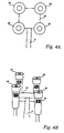
- FIGS 4A - 4C show an embodiment of the present invention, in which four teatcups 60, 62, 64, 66 are disengagably disposed in a vertically displaced relationship on the end portion 30.
- Each of the teatcups is provided with a bar code 70, for allowing identification thereof by means of a teat location means 32 in the form of a laser sensor (cf. figure 3C ).
- the laser sensor is of the kind described in detail in WO 97/15900 , and is furthermore able to read bar codes.
- the teatcup 60 is to be attached to the rear teat 20 of the udder 18.
- the laser sensor 32 locates the position of the teat 20 and furthermore establishes the identity of the teatcup 60. It is desirable that none of the other teatcups is allowed to be attached to that teat, as it would cause troublesome further teacup attachment.
- the teatcup 60 When the teatcup 60 has been attached to the teat 20, the teatcup is released from the end portion 30. The teatcup 62 is then ready to be attached to the teat 22.
- the teatcups are individually detached from the relevant teat and returned to the end portion 30 of the robot arm 6 by means of e.g. a cord (not shown).
- the attachment of the teatcups 60, 62, 64, 66 to the end portion 30 is performed by means of electromagnets (not shown).
Landscapes
- Life Sciences & Earth Sciences (AREA)
- Animal Husbandry (AREA)
- Environmental Sciences (AREA)
- Manipulator (AREA)
- Housing For Livestock And Birds (AREA)
- Toys (AREA)
- Catching Or Destruction (AREA)
Claims (9)
- Vorrichtung zum automatischen Melken eines Tiers, mit einer Mehrzahl von Zitzenbechern (60, 62, 64, 66), die jeweils ein Zitzeneintrittsende (17a) aufweisen, und mit einem beweglichen Arm (6), um die Zitzenbecher zu einer Zitze des zu melkenden Tieres zu bewegen und daran zu befestigen, wobei das Zitzeneintrittsende (17a) mindestens eines der Zitzenbecher während der Bewegung in Richtung der Zitze mittels des beweglichen Arms (6) bezüglich des Arms (6) auf einem Niveau gehalten wird, das sich von dem eines Zitzeneintrittsendes (17a) eines weiteren Zitzenbechers unterscheidet, wenn dieser bezüglich des beweglichen Arms gehalten wird, wobeia) der bewegliche Arm (6) eine Endpartie (30) zum Halten einer Mehrzahl von Zitzenbechern (60, 62, 64, 66) aufweist, wobei der Zitzenbecher auf einem Niveau gehalten wird, das sich von dem eines weiteren von der Endpartie (30) gehaltenen Zitzenbechers unterscheidet,b) der mindestens eine Zitzenbecher (60) und der weitere Zitzenbecher (62, 64, 66) so zum Zusammenwirken mit einem Befestigungsmittel der Endpartie (30) angeordnet sind, dass sie bezüglich der Endpartie auf verschiedenen Niveaus gehalten werden undc) das Verbindungsmittel Elektromagnete zur Befestigung der Zitzenbecher an der Endpartie aufweist.
- Vorrichtung nach Anspruch 1, dadurch gekennzeichnet, dass der mindestens eine Zitzenbecher (60) und der weitere Zitzenbecher (62, 64, 66) unabhängig voneinander von der Endpartie (30) weg bewegbar sind.
- Vorrichtung nach einem der voranstehenden Ansprüche, dadurch gekennzeichnet, dass der mindestens eine Zitzenbecher und der bewegliche Arm eine Identifizierungseinrichtung (32, 70) aufweisen, die eine Identifizierung des mindestens einen Zitzenbechers erlaubt.
- Vorrichtung nach Anspruch 3, dadurch gekennzeichnet, dass der mindestens eine Zitzenbecher mit einem Strichcode (70) und der bewegliche Arm mit einem Laserlesegerät (32) zum Lesen des Strichcodes (70) versehen ist.
- Vorrichtung nach einem der voranstehenden Ansprüche, dadurch gekennzeichnet, dass das Zitzeneintrittsende (17a) des mindestens einen Zitzenbechers in einer vertikalen Ebene betrachtet, sich auf einem höheren Niveau befindet als das Zitzeneintrittsende eines weiteren Zitzenbechers.
- Vorrichtung nach einem der Ansprüche 1 bis 5, dadurch gekennzeichnet, dass der bewegliche Arm ein Roboterarm (6) ist.
- Vorrichtung nach Anspruch 6, dadurch gekennzeichnet, dass der Roboterarm mit einem Lasersensor (32) versehen ist.
- Vorrichtung nach Anspruch 7, dadurch gekennzeichnet, dass der Lasersensor (32) einen Lasersender zur Bildung einer Linie, wie beispielsweise einen Scannerlaserstrahl oder eine stabile oder scannende Laserebene, sowie einen Laserempfänger, wie beispielsweise eine Bilderfassungsvorrichtung, aufweist.
- Vorrichtung nach Anspruch 8, dadurch gekennzeichnet, dass der Lasersensor (32) zum Lesen von Strichcodes (70) bestimmt ist.
Priority Applications (1)
| Application Number | Priority Date | Filing Date | Title |
|---|---|---|---|
| DE69915839T DE69915839T3 (de) | 1998-07-24 | 1999-07-23 | Vorrichtung zum automatischen melken von tieren |
Applications Claiming Priority (3)
| Application Number | Priority Date | Filing Date | Title |
|---|---|---|---|
| SE9802611A SE517285C2 (sv) | 1998-07-24 | 1998-07-24 | Anordning för automatisk mjölkning av ett djur |
| SE9802611 | 1998-07-24 | ||
| PCT/SE1999/001304 WO2000004766A1 (en) | 1998-07-24 | 1999-07-23 | An apparatus for automatically milking an animal |
Publications (3)
| Publication Number | Publication Date |
|---|---|
| EP1100314A1 EP1100314A1 (de) | 2001-05-23 |
| EP1100314B1 EP1100314B1 (de) | 2004-03-24 |
| EP1100314B2 true EP1100314B2 (de) | 2011-10-19 |
Family
ID=20412149
Family Applications (1)
| Application Number | Title | Priority Date | Filing Date |
|---|---|---|---|
| EP99943530A Expired - Lifetime EP1100314B2 (de) | 1998-07-24 | 1999-07-23 | Vorrichtung zum automatischen melken von tieren |
Country Status (9)
| Country | Link |
|---|---|
| US (1) | US6575116B1 (de) |
| EP (1) | EP1100314B2 (de) |
| JP (1) | JP2002521009A (de) |
| AU (1) | AU5660599A (de) |
| CA (1) | CA2338732C (de) |
| DE (1) | DE69915839T3 (de) |
| IL (1) | IL140941A0 (de) |
| SE (1) | SE517285C2 (de) |
| WO (1) | WO2000004766A1 (de) |
Families Citing this family (16)
| Publication number | Priority date | Publication date | Assignee | Title |
|---|---|---|---|---|
| US20080248466A1 (en) * | 2004-07-30 | 2008-10-09 | Tm Bioscience Pgx Inc. | Method Of Detecting Mutations In The Gene Encoding Cytochrome P450-2C19 |
| SE529127C2 (sv) * | 2005-09-02 | 2007-05-08 | Delaval Holding Ab | Detekteringsarrangemang jämte -metod för en magnetisk gripanordning |
| NL1032429C2 (nl) * | 2006-09-05 | 2008-03-06 | Maasland Nv | Werkwijze voor het besturen van melkinrichting, alsmede software programma voor en inrichting met deze werkwijze. |
| SE531487C2 (sv) * | 2007-03-23 | 2009-04-21 | Delaval Holding Ab | En spenkopphanterande anordning och en lagringsanordning för spenkoppar |
| NL1034502C2 (nl) * | 2007-10-12 | 2009-04-15 | Lely Patent Nv | Melkinrichting. |
| EP2060172B1 (de) | 2007-11-16 | 2014-12-17 | DeLaval Holding AB | Vorrichtung und Verfahren zum Ansetzen eines Zitzenbechers |
| CA2730439A1 (en) * | 2008-07-17 | 2010-01-21 | Delaval Holding Ab | A system and method for automatically obtaining a milk sample and performing cleaning |
| EP2369911B1 (de) | 2008-11-26 | 2016-01-06 | DeLaval Holding AB | Handhabung von Zitzenbechern |
| US20120143375A1 (en) * | 2009-08-26 | 2012-06-07 | Delaval Holding Ab | Milking robot and method for teat cup attachment |
| US9357749B2 (en) | 2010-01-29 | 2016-06-07 | Gea Houle Inc. | Rotary milking station, kit for assembling the same, and methods of assembling and operating associated thereto |
| CN102905518B (zh) * | 2010-06-17 | 2015-03-11 | 利拉伐控股有限公司 | 抓取器、挤奶机器人及挤奶装置 |
| WO2012057678A1 (en) * | 2010-10-26 | 2012-05-03 | Delaval Holding Ab | A control system for at least one flexible tubular element connected to a cup-shaped member |
| PL2934098T3 (pl) * | 2012-12-19 | 2017-07-31 | Delaval Holding Ab | Układ udojowy, zestaw wymienialnych, zużywalnych części i sposób dla układu udojowego |
| NL2010406C2 (nl) | 2013-03-07 | 2014-09-10 | Rotec Engineering B V | Grijper voor het aanbrengen van melkbekers bij een te melken dier, robotarm en melkmachine voorzien daarvan, en werkwijze daarvoor. |
| NL2015970B1 (nl) * | 2015-12-16 | 2017-06-30 | Lely Patent Nv | Melkinrichting |
| NL2026125B1 (nl) * | 2020-07-23 | 2022-03-28 | Lely Patent Nv | Robotmelkinrichting |
Citations (4)
| Publication number | Priority date | Publication date | Assignee | Title |
|---|---|---|---|---|
| EP0300582A1 (de) † | 1987-07-23 | 1989-01-25 | C. van der Lely N.V. | Verfahren und Vorrichtung zum Melken eines Tieres |
| EP0302559A1 (de) † | 1987-08-05 | 1989-02-08 | Gascoigne-Melotte B.V. | Melkmaschine |
| EP0360354A1 (de) † | 1988-09-21 | 1990-03-28 | C. van der Lely N.V. | Vorrichtung zum Melken eines Tieres sowie zum Ansetzen der Melkbecher |
| NL9200093A (nl) † | 1992-01-17 | 1993-08-16 | Lely Nv C Van Der | Melkmachine. |
Family Cites Families (18)
| Publication number | Priority date | Publication date | Assignee | Title |
|---|---|---|---|---|
| NL193648C (nl) * | 1986-08-27 | 2000-06-06 | Lely Nv C Van Der | Inrichting voor het melken van dieren. |
| DE4113700A1 (de) | 1991-04-26 | 1992-10-29 | Dieter Dipl Ing Schillingmann | Verfahren zum automatischen melken von in melkboxen stehenden milchkuehen, sowie melkbox, roboter und melkmodul zur durchfuehrung dieses verfahrens |
| NL9101064A (nl) | 1991-06-20 | 1993-01-18 | Gascoigne Melotte Bv | Inrichting voor het aanleggen respectievelijk verwijderen van een stel speenbekers bij dieren. |
| NL9200419A (nl) | 1992-03-06 | 1993-10-01 | Lely Nv C Van Der | Inrichting voor het melken van dieren. |
| NL9200639A (nl) | 1992-04-06 | 1993-11-01 | Lely Nv C Van Der | Inrichting voor het automatisch melken van dieren. |
| NL9301751A (nl) | 1993-10-11 | 1995-05-01 | Texas Industries Inc | Inrichting voor het automatisch melken van dieren. |
| NL9401113A (nl) * | 1994-07-04 | 1996-02-01 | Maasland Nv | Constructie met een inrichting voor het automatisch melken van dieren. |
| NL9401801A (nl) * | 1994-08-23 | 1996-04-01 | Maasland Nv | Constructie met een inrichting voor het melken van dieren. |
| NL1000010C2 (nl) * | 1995-04-03 | 1996-10-04 | Maasland Nv | Werkwijze voor het positioneren van voor het automatisch melken benodigde middelen onder de uier van een dier, alsmede inrichting waarin deze werkwijze kan worden toegepast. |
| US6116188A (en) * | 1996-04-24 | 2000-09-12 | Van Der Lely; Cornelis | Method of milking animals |
| EP0848588B1 (de) * | 1996-07-05 | 2001-10-24 | Maasland N.V. | Vorrichtung zum automatischen melken von tieren |
| NL1004922C2 (nl) * | 1996-12-31 | 1998-07-01 | Prolion Bv | Inrichting en werkwijze voor het melken van dieren. |
| NL1005255C2 (nl) * | 1997-02-12 | 1998-08-13 | Maasland Nv | Werkwijze voor het melken van dieren. |
| SE9701231D0 (sv) * | 1997-04-04 | 1997-04-04 | Alfa Laval Agri Ab | Apparatus and method for recognising and determining the position of part of an animal |
| SE9701310D0 (sv) * | 1997-04-11 | 1997-04-11 | Alfa Laval Agri Ab | A teatcup magazine, a milking arrangement, and a method of handling a teatcup |
| SE9702628D0 (sv) * | 1997-07-07 | 1997-07-07 | Alfa Laval Agri Ab | An animal related apparatus |
| ATE268107T1 (de) * | 1997-11-14 | 2004-06-15 | Delaval Holding Ab | Vorrichtung zur durchführung einer sich auf tieren beziehenden handlung |
| SE9704174D0 (sv) * | 1997-11-14 | 1997-11-14 | Alfa Laval Agri Ab | an automatic milking apparatus |
-
1998
- 1998-07-24 SE SE9802611A patent/SE517285C2/sv not_active IP Right Cessation
-
1999
- 1999-07-23 CA CA002338732A patent/CA2338732C/en not_active Expired - Fee Related
- 1999-07-23 DE DE69915839T patent/DE69915839T3/de not_active Expired - Lifetime
- 1999-07-23 EP EP99943530A patent/EP1100314B2/de not_active Expired - Lifetime
- 1999-07-23 JP JP2000560772A patent/JP2002521009A/ja active Pending
- 1999-07-23 WO PCT/SE1999/001304 patent/WO2000004766A1/en not_active Ceased
- 1999-07-23 US US09/744,401 patent/US6575116B1/en not_active Expired - Lifetime
- 1999-07-23 IL IL14094199A patent/IL140941A0/xx unknown
- 1999-07-27 AU AU56605/99A patent/AU5660599A/en not_active Abandoned
Patent Citations (4)
| Publication number | Priority date | Publication date | Assignee | Title |
|---|---|---|---|---|
| EP0300582A1 (de) † | 1987-07-23 | 1989-01-25 | C. van der Lely N.V. | Verfahren und Vorrichtung zum Melken eines Tieres |
| EP0302559A1 (de) † | 1987-08-05 | 1989-02-08 | Gascoigne-Melotte B.V. | Melkmaschine |
| EP0360354A1 (de) † | 1988-09-21 | 1990-03-28 | C. van der Lely N.V. | Vorrichtung zum Melken eines Tieres sowie zum Ansetzen der Melkbecher |
| NL9200093A (nl) † | 1992-01-17 | 1993-08-16 | Lely Nv C Van Der | Melkmachine. |
Also Published As
| Publication number | Publication date |
|---|---|
| EP1100314A1 (de) | 2001-05-23 |
| SE9802611D0 (sv) | 1998-07-24 |
| AU5660599A (en) | 2000-02-14 |
| WO2000004766A1 (en) | 2000-02-03 |
| SE9802611L (sv) | 2000-01-25 |
| SE517285C2 (sv) | 2002-05-21 |
| IL140941A0 (en) | 2002-02-10 |
| CA2338732C (en) | 2008-11-18 |
| EP1100314B1 (de) | 2004-03-24 |
| US6575116B1 (en) | 2003-06-10 |
| DE69915839T2 (de) | 2005-02-03 |
| CA2338732A1 (en) | 2000-02-03 |
| DE69915839D1 (de) | 2004-04-29 |
| DE69915839T3 (de) | 2012-03-22 |
| JP2002521009A (ja) | 2002-07-16 |
Similar Documents
| Publication | Publication Date | Title |
|---|---|---|
| EP1100314B2 (de) | Vorrichtung zum automatischen melken von tieren | |
| US6363883B1 (en) | Animal related apparatus | |
| EP1131995B1 (de) | Verfahren und Gerät zum Melken von Tieren | |
| US6431116B1 (en) | Apparatus for performing animal related operations | |
| EP0900522A1 (de) | Melkanlage | |
| NL1015559C2 (nl) | Melksysteem met driedimensionale beeldvorming. | |
| EP0741512B1 (de) | Verfahren und gerät zum automatischen melken von tieren sowie kühen | |
| US8689735B2 (en) | Handling of teat cups | |
| EP0880889B1 (de) | Vorrichtung zum Melken von Tieren | |
| EP0700245B1 (de) | Konstruktion mit einem gerät zum melken von tieren | |
| US20080022933A1 (en) | Gripper Device, Robot Arm, and Milking Robot | |
| US6116188A (en) | Method of milking animals | |
| EP3096604B1 (de) | Greifer zum anordnen von melkbechern an einem tier zum melken, roboterarm und melkmaschine damit sowie verfahren dafür | |
| EP0611004B1 (de) | Vorrichtung zum Melken von Tieren | |
| EP0804874A2 (de) | Konstruktion zum automatischen Melken von Tieren | |
| JP2000506744A (ja) | 動物の自動搾乳装置を含む構造 | |
| EP0617885A1 (de) | Konstruktion zum automatischen Melken von Tieren | |
| EP0673596A1 (de) | Konstruktion mit Gerät zum Melken von Tieren |
Legal Events
| Date | Code | Title | Description |
|---|---|---|---|
| PUAI | Public reference made under article 153(3) epc to a published international application that has entered the european phase |
Free format text: ORIGINAL CODE: 0009012 |
|
| 17P | Request for examination filed |
Effective date: 20010129 |
|
| AK | Designated contracting states |
Kind code of ref document: A1 Designated state(s): AT BE CH CY DE DK ES FI FR GB GR IE IT LI LU MC NL PT SE |
|
| 17Q | First examination report despatched |
Effective date: 20030127 |
|
| GRAP | Despatch of communication of intention to grant a patent |
Free format text: ORIGINAL CODE: EPIDOSNIGR1 |
|
| GRAS | Grant fee paid |
Free format text: ORIGINAL CODE: EPIDOSNIGR3 |
|
| GRAA | (expected) grant |
Free format text: ORIGINAL CODE: 0009210 |
|
| AK | Designated contracting states |
Kind code of ref document: B1 Designated state(s): DE FR GB IT NL SE |
|
| PG25 | Lapsed in a contracting state [announced via postgrant information from national office to epo] |
Ref country code: IT Free format text: LAPSE BECAUSE OF FAILURE TO SUBMIT A TRANSLATION OF THE DESCRIPTION OR TO PAY THE FEE WITHIN THE PRESCRIBED TIME-LIMIT;WARNING: LAPSES OF ITALIAN PATENTS WITH EFFECTIVE DATE BEFORE 2007 MAY HAVE OCCURRED AT ANY TIME BEFORE 2007. THE CORRECT EFFECTIVE DATE MAY BE DIFFERENT FROM THE ONE RECORDED. Effective date: 20040324 Ref country code: FR Free format text: LAPSE BECAUSE OF FAILURE TO SUBMIT A TRANSLATION OF THE DESCRIPTION OR TO PAY THE FEE WITHIN THE PRESCRIBED TIME-LIMIT Effective date: 20040324 |
|
| REG | Reference to a national code |
Ref country code: GB Ref legal event code: FG4D |
|
| REG | Reference to a national code |
Ref country code: IE Ref legal event code: FG4D |
|
| REF | Corresponds to: |
Ref document number: 69915839 Country of ref document: DE Date of ref document: 20040429 Kind code of ref document: P |
|
| PG25 | Lapsed in a contracting state [announced via postgrant information from national office to epo] |
Ref country code: SE Free format text: LAPSE BECAUSE OF FAILURE TO SUBMIT A TRANSLATION OF THE DESCRIPTION OR TO PAY THE FEE WITHIN THE PRESCRIBED TIME-LIMIT Effective date: 20040624 |
|
| PG25 | Lapsed in a contracting state [announced via postgrant information from national office to epo] |
Ref country code: GB Free format text: LAPSE BECAUSE OF NON-PAYMENT OF DUE FEES Effective date: 20040723 |
|
| PLBI | Opposition filed |
Free format text: ORIGINAL CODE: 0009260 |
|
| PLAX | Notice of opposition and request to file observation + time limit sent |
Free format text: ORIGINAL CODE: EPIDOSNOBS2 |
|
| 26 | Opposition filed |
Opponent name: OCTROOIBUREAU VAN DER LELY N.V. Effective date: 20041208 |
|
| EN | Fr: translation not filed | ||
| GBPC | Gb: european patent ceased through non-payment of renewal fee |
Effective date: 20040723 |
|
| NLR1 | Nl: opposition has been filed with the epo |
Opponent name: OCTROOIBUREAU VAN DER LELY N.V. |
|
| REG | Reference to a national code |
Ref country code: IE Ref legal event code: MM4A |
|
| PLAX | Notice of opposition and request to file observation + time limit sent |
Free format text: ORIGINAL CODE: EPIDOSNOBS2 |
|
| PLBB | Reply of patent proprietor to notice(s) of opposition received |
Free format text: ORIGINAL CODE: EPIDOSNOBS3 |
|
| RDAF | Communication despatched that patent is revoked |
Free format text: ORIGINAL CODE: EPIDOSNREV1 |
|
| APBP | Date of receipt of notice of appeal recorded |
Free format text: ORIGINAL CODE: EPIDOSNNOA2O |
|
| APAH | Appeal reference modified |
Free format text: ORIGINAL CODE: EPIDOSCREFNO |
|
| APBQ | Date of receipt of statement of grounds of appeal recorded |
Free format text: ORIGINAL CODE: EPIDOSNNOA3O |
|
| APBU | Appeal procedure closed |
Free format text: ORIGINAL CODE: EPIDOSNNOA9O |
|
| PUAH | Patent maintained in amended form |
Free format text: ORIGINAL CODE: 0009272 |
|
| STAA | Information on the status of an ep patent application or granted ep patent |
Free format text: STATUS: PATENT MAINTAINED AS AMENDED |
|
| 27A | Patent maintained in amended form |
Effective date: 20111019 |
|
| AK | Designated contracting states |
Kind code of ref document: B2 Designated state(s): DE FR GB IT NL SE |
|
| REG | Reference to a national code |
Ref country code: DE Ref legal event code: R102 Ref document number: 69915839 Country of ref document: DE |
|
| REG | Reference to a national code |
Ref country code: DE Ref legal event code: R102 Ref document number: 69915839 Country of ref document: DE Effective date: 20111019 |
|
| REG | Reference to a national code |
Ref country code: NL Ref legal event code: T3 |
|
| PGFP | Annual fee paid to national office [announced via postgrant information from national office to epo] |
Ref country code: NL Payment date: 20150709 Year of fee payment: 17 |
|
| PGFP | Annual fee paid to national office [announced via postgrant information from national office to epo] |
Ref country code: DE Payment date: 20160720 Year of fee payment: 18 |
|
| REG | Reference to a national code |
Ref country code: NL Ref legal event code: MM Effective date: 20160801 |
|
| PG25 | Lapsed in a contracting state [announced via postgrant information from national office to epo] |
Ref country code: NL Free format text: LAPSE BECAUSE OF NON-PAYMENT OF DUE FEES Effective date: 20160801 |
|
| REG | Reference to a national code |
Ref country code: DE Ref legal event code: R119 Ref document number: 69915839 Country of ref document: DE |
|
| PG25 | Lapsed in a contracting state [announced via postgrant information from national office to epo] |
Ref country code: DE Free format text: LAPSE BECAUSE OF NON-PAYMENT OF DUE FEES Effective date: 20180201 |