EP1100995B1 - Stützvorrichtung für eine bewegliche last - Google Patents
Stützvorrichtung für eine bewegliche last Download PDFInfo
- Publication number
- EP1100995B1 EP1100995B1 EP00936940A EP00936940A EP1100995B1 EP 1100995 B1 EP1100995 B1 EP 1100995B1 EP 00936940 A EP00936940 A EP 00936940A EP 00936940 A EP00936940 A EP 00936940A EP 1100995 B1 EP1100995 B1 EP 1100995B1
- Authority
- EP
- European Patent Office
- Prior art keywords
- support plate
- runners
- closed path
- closed
- path
- Prior art date
- Legal status (The legal status is an assumption and is not a legal conclusion. Google has not performed a legal analysis and makes no representation as to the accuracy of the status listed.)
- Expired - Lifetime
Links
- 230000010355 oscillation Effects 0.000 claims description 9
- 230000007246 mechanism Effects 0.000 claims description 5
- 239000002184 metal Substances 0.000 claims description 4
- 238000006073 displacement reaction Methods 0.000 claims description 2
- 230000002787 reinforcement Effects 0.000 claims 1
- 229920001343 polytetrafluoroethylene Polymers 0.000 description 9
- 239000004810 polytetrafluoroethylene Substances 0.000 description 9
- 239000011248 coating agent Substances 0.000 description 5
- 238000000576 coating method Methods 0.000 description 5
- 239000000463 material Substances 0.000 description 5
- 238000000034 method Methods 0.000 description 5
- 229910000831 Steel Inorganic materials 0.000 description 4
- 238000010276 construction Methods 0.000 description 4
- 239000010959 steel Substances 0.000 description 4
- 210000000056 organ Anatomy 0.000 description 3
- 229910001220 stainless steel Inorganic materials 0.000 description 3
- 239000010935 stainless steel Substances 0.000 description 3
- 238000010586 diagram Methods 0.000 description 2
- 208000032368 Device malfunction Diseases 0.000 description 1
- 230000006835 compression Effects 0.000 description 1
- 238000007906 compression Methods 0.000 description 1
- 229920001971 elastomer Polymers 0.000 description 1
- 239000000806 elastomer Substances 0.000 description 1
- 230000008520 organization Effects 0.000 description 1
- 230000003071 parasitic effect Effects 0.000 description 1
- 229920001084 poly(chloroprene) Polymers 0.000 description 1
- -1 polytetrafluoroethylene Polymers 0.000 description 1
- 230000003014 reinforcing effect Effects 0.000 description 1
- 125000006850 spacer group Chemical group 0.000 description 1
Images


Classifications
-
- F—MECHANICAL ENGINEERING; LIGHTING; HEATING; WEAPONS; BLASTING
- F16—ENGINEERING ELEMENTS AND UNITS; GENERAL MEASURES FOR PRODUCING AND MAINTAINING EFFECTIVE FUNCTIONING OF MACHINES OR INSTALLATIONS; THERMAL INSULATION IN GENERAL
- F16C—SHAFTS; FLEXIBLE SHAFTS; ELEMENTS OR CRANKSHAFT MECHANISMS; ROTARY BODIES OTHER THAN GEARING ELEMENTS; BEARINGS
- F16C29/00—Bearings for parts moving only linearly
-
- B—PERFORMING OPERATIONS; TRANSPORTING
- B65—CONVEYING; PACKING; STORING; HANDLING THIN OR FILAMENTARY MATERIAL
- B65G—TRANSPORT OR STORAGE DEVICES, e.g. CONVEYORS FOR LOADING OR TIPPING, SHOP CONVEYOR SYSTEMS OR PNEUMATIC TUBE CONVEYORS
- B65G7/00—Devices for assisting manual moving or tilting heavy loads
- B65G7/02—Devices adapted to be interposed between loads and the ground or floor, e.g. crowbars with means for assisting conveyance of loads
-
- E—FIXED CONSTRUCTIONS
- E01—CONSTRUCTION OF ROADS, RAILWAYS, OR BRIDGES
- E01D—CONSTRUCTION OF BRIDGES, ELEVATED ROADWAYS OR VIADUCTS; ASSEMBLY OF BRIDGES
- E01D19/00—Structural or constructional details of bridges
- E01D19/04—Bearings; Hinges
- E01D19/048—Bearings being adjustable once installed; Bearings used in incremental launching
-
- F—MECHANICAL ENGINEERING; LIGHTING; HEATING; WEAPONS; BLASTING
- F16—ENGINEERING ELEMENTS AND UNITS; GENERAL MEASURES FOR PRODUCING AND MAINTAINING EFFECTIVE FUNCTIONING OF MACHINES OR INSTALLATIONS; THERMAL INSULATION IN GENERAL
- F16C—SHAFTS; FLEXIBLE SHAFTS; ELEMENTS OR CRANKSHAFT MECHANISMS; ROTARY BODIES OTHER THAN GEARING ELEMENTS; BEARINGS
- F16C2350/00—Machines or articles related to building
Definitions
- the invention relates to devices intended to be interposed between a base and a heavy load in order to support this load in such a way that it can be moved horizontally relative to the base.
- the deck of the structure is built on the embankment adjacent to its site by fixed workshops. which greatly facilitates the organization of the site.
- the deck is built section by section. Once that a section has been built, it is pushed by actuators along the path of the bridge, so that the construction of the next stretch.
- the sections of the deck slide over the already made piles of the work.
- FIGS 1 to 4 show a platform 1 installed at the edge of a breach 2 which will be spanned by the bridge.
- Bridge deck 3 is constructed section by section on this platform 1.
- a suitable thrust member 4 is located at the rear of platform 1 during the completion of each section of deck 3 ( Figures 1 and 3). Once this section is complete, the organ 4 la pushes towards the breach in order to advance the bridge deck and free the construction space on platform 1 ( Figures 2 and 4), the deck taking support on the piles 7 of the bridge previously made.
- the member 4 is supported at the rear of the section deck built, and pulls by means of a hydraulic motor on elements such as cables 5 anchored in a suitable foundation 6 located at the end of the platform 1 adjacent to the breach 2, the member 4 then moving towards the breach to advance the apron.
- the present invention is relates more particularly to the systems used to slide the deck 3 of the bridge at the top of the piers 7 during the pushing operations.
- sliding saddles 8 are used which are fix batteries 7 at the top ( Figures 1 to 5), and which cooperate with sliding 9 engaged under the deck 3 as it progresses. These pads 9 are not shown in Figures 1 to 4, but they are visible in Figure 5.
- at least two sliding saddles 8 are provided on the width of each stack 7 so that the support of the deck 3 is stable.
- a front spout 10 is fixed in overhang in front of the first section of the apron 3. This forebeak rests on the batteries to prevent the apron from tipping into the breach during the first operations thrust. It also limits the cantilever mass between two batteries in the current part of the work.
- the saddle 8 comprises a support block 11 whose upper face is coated with a metal plate 12 in polished stainless steel (Figure 5).
- Each sliding shoe 9 ( Figure 6) is made from a deformable material. such as "Neoprene", reinforced by one or more metallic frets 13.
- the underside of the skate has a coating 14 having a low friction coefficient with the metal of the plate 12.
- the coating material 14 is for example polytetrafluoroethylene (PTFE).
- the pad 9 simply consists of a steel hoop 13 sandwiched between the PTFE coating 14 and the deformable material 15 on the side of the upper face of the skate.
- the deformable material 15 comes in contact with the underside of the deck 3, of which it marries any irregularities, while the face coated with PTFE 14 slides on the saddle 8.
- Patent application FR-A-2 597 520 describes a device intended for replace the saddle and pad system to allow exempt operators.
- This device comprises a rigid core in the form of flattened cylinder, and a continuous strip of reinforced elastomer arranged around the core. The strip slides on the core when it receives the load of the deck in advancing. In practice, this device malfunctions for very heavy loads. heavy.
- Patent applications DE-A-28 11 200 and FR-A-2 437 466 describe sliding saddles fitted with pads assembled to form a band continuous arranged around a plate.
- the tape has a closed path around the plate, along which the skates keep their face from sliding towards the plate.
- the skates are relatively small and many to be able to follow the curvature of their trajectory at the ends of the plaque.
- the object of the present invention is to propose an effective device and relatively simple to automatically perform the function of sliding of a heavy load (for example a pushed bridge deck) by relative to a base (for example a bridge stack).
- a heavy load for example a pushed bridge deck
- a base for example a bridge stack
- the invention thus provides a device for supporting a mobile load, comprising a support plate and pads, in which the support plate support and each shoe have respective sliding faces for the sliding the pads on the support plate, the device further comprising spacing means for defining an interval along the plate support opposite its sliding face, and drive means skids following a closed path around the support plate, the closed trajectory comprising a forward path in which the skates slide on the support plate, characterized in that the closed path includes a return path in which the pads pass through said gap with their sliding face oriented opposite the plate support.
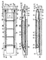
- Figure 7 shows a sliding pad 19 whose general structure is similar to that previously described.
- the skate has in particular a face of slip 14 covered with a material with a low coefficient of slip such as PTFE.
- a reinforcing hoop 13 On an edge 20 of the skate, a reinforcing hoop 13 has a extension 21 adapted to receive an axis 22 providing an articulation of the pad around a direction parallel to the edge 20.
- the axis 22 has its two ends connected to links of two parallel chains 24 arranged laterally on either side of the pads 19.
- the two chains 24 drive the pads 19 following a closed loop path.
- the chains 24 are guided by toothed wheels 32,33 which on the one hand delimit a forward path of the skates, extending above a support plate 25. and secondly a return path in which the pads pass in an interval 26 formed below the support plate 25.
- the support plate 25 is for example made of steel. His face upper, covered by a sheet of polished stainless steel 27, forms a face of additional sliding of the underside of the pads comprising the PTFE coating 14.
- two lateral supports 30, 31 are arranged on either side of the plates 25, 28. These supports 30, 31 carry the axes of rotation 34.35 of the toothed wheels 32. 33 on which mesh the chains 24.
- the axis 34 of the wheels teeth 32 can extend across the device. from a lateral support 30 to the other.
- the axes of rotation 35 of the toothed wheels 33, respectively carried by the lateral supports 31, do not do not extend in the interval between the two toothed wheels 33.
- each shoe 19 along which it is articulated relative to to the chain 24, is directed towards the front end of the device, and the deck 3 in principle progresses from the rear end to the front end.
- the levers 40 are fixed to an axis 42 parallel to the axes of rotation 35 cogwheels.
- the axis 42 is associated with a cam mechanism for control the oscillation of the levers 40.
- These cams 43 actuate arms 44, fixed to the axis of rotation 42 in its part projecting from the supports side. 31, and extending transversely to the levers 40.
- the mobile assembly 40-42, 44 tends to tilt towards the position where the roller 41 is flush with the upper surface of the base plate 28. But in certain phases of the movement, the cams 43 activate the arm 44 for bringing the roller 41 into the position illustrated in FIG. 10 where it is flush with the upper face of the support plate 25.
- the admissible compression stresses on the pads and on the concrete are of the same order of magnitude as in the case of stools traditional of the type shown in Figure 5. which allows to support in load shifting of several megaewtons, with a device of moderate overall thickness. Several of these devices can be arranged in series or in parallel to locally increase the capacity bearing.
- the base plate 28 can then be shared between several devices. This plate 28 can also be provided on its underside with a piston of the type of those conventionally used in pot supports, in order to allow the device to adapt to possible rotations of the deck without transmit parasitic efforts.
Landscapes
- Engineering & Computer Science (AREA)
- Mechanical Engineering (AREA)
- Architecture (AREA)
- Civil Engineering (AREA)
- Structural Engineering (AREA)
- General Engineering & Computer Science (AREA)
- Bridges Or Land Bridges (AREA)
- Forklifts And Lifting Vehicles (AREA)
- Vehicle Body Suspensions (AREA)
- Current-Collector Devices For Electrically Propelled Vehicles (AREA)
- Mechanical Control Devices (AREA)
- Specific Sealing Or Ventilating Devices For Doors And Windows (AREA)
Claims (8)
- Stützvorrichtung für eine bewegliche Last (3), umfassend eine Tragplatte (25) und Schlitten (19), bei welcher die Tragplatte und jeder Schlitten jeweilige Gleitflächen (27, 14) für das Gleiten der Schlitten auf der Tragplatte aufweisen, wobei die Vorrichtung ferner Beabstandungsmittel (29) umfasst, um einen Zwischenraum (26) längs der Tragplatte auf der deren Gleitfläche abgewandter Seite festzulegen sowie Mittel (24, 32, 33) zum Antreiben der Schlitten gemäß einer geschlossenen Bahn um die Tragplatte herum, wobei die geschlossene Bahn einen Hinweg umfasst, in dem die Schlitten auf der Tragplatte gleiten, dadurch gekennzeichnet, dass die geschlossene Bahn einen Rückweg beinhaltet, in welchem die Schlitten in dem Zwischenraum verlaufen, wobei ihre Gleitflächen von der Tragplatte abgewandt orientiert sind.
- Vorrichtung nach Anspruch 1, in der die Antriebsmittel mindestens ein als eine geschlossene Schleife ausgebildetes Antriebselement (24) umfassen, das bezüglich der Schlitten seitlich angeordnet ist, sowie Mittel (32, 33) zum Führen des Antriebselements um die geschlossene Bahn festzulegen, in welcher jeder Schlitten (19) an dem Antriebselement gemäß einer Achse (22) angelenkt ist, die zu der geschlossenen Bahn orthogonal verläuft und einem Rand des Schlittens benachbart ist, und in welcher der Rand (20)des Schlittens auf ein Ende der geschlossenen Bahn zu gerichtet ist, das von der Tragplatte um eine Distanz beabstandet ist, die wenigstens gleich der Länge des Schlittens ist, wobei die Führungsmittel (33) an diesem Ende derart angebracht sind, dass sie den Schlitten der geschlossenen Bahn folgen lassen, ohne diesen umzukehren.
- Vorrichtung nach Anspruch 2, in welcher die Antriebsmittel zwei zu einer geschlossenen Schleife ausgebildete Antriebselemente (24) umfassen, welche beidseits der Schlitten (19) parallel angeordnet sind, und In welcher die Führungsmittel an dem Ende der geschlossenen Bahn ein Paar drehbarer Räder (33) aufweisen, welche jeweils die beiden Antriebselemente aufnehmen, wobei der Abstand zwischen den beiden Rädern des Paars für den Durchtritt der Schlitten frei ist.
- Vorrichtung nach Anspruch 2 oder 3, außerdem umfassend wenigstens einen Hebel (40), der sich in dem Raum hin- und herbewegt, der zwischen der Tragplatte (25) und dem Ende der geschlossenen Bahn angeordnet ist, so dass die Schlitten (19) abgestützt sind, wenn sie der Bahn an dem Ende folgen.
- Vorrichtung nach Anspruch 4, in welcher die Hin- und Herbewegung des Hebels. (40) gesteuert ist, um die Schlitten (19) in der Nähe des Endes der geschlossenen Bahn bei einer Umkehrung der Verlagerungsrichtung der Last (3) anzuheben, um sie der geschlossenen Bahn in umgekehrter Richtung folgen zu lassen.
- Vorrichtung nach Anspruch 4 oder 5, in welcher die Hin- und Herbewegung des Hebels (40) durch einen Nockenmechanismus (43) gesteuert ist, der von den Führungsmitteln (33, 35) angetrieben ist.
- Vorrichtung nach einem der Ansprüche 2 bis 6, in welcher jedes zu einer Schleife geschlossene Antriebselement eine Kette (24) ist, die mit Zahnrädern (32, 33) in Eingriff steht, welche Teil der Führungsmittel sind.
- Vorrichtung nach einem der vorhergehenden Ansprüche, in welcher jeder Schlitten (19) wenigstens eine Metallarmierung (13) aufweist, mit welcher Mittel (21) zum Anlenken an den Antriebsmitteln verbunden sind.
Applications Claiming Priority (3)
| Application Number | Priority Date | Filing Date | Title |
|---|---|---|---|
| FR9906867A FR2794442B1 (fr) | 1999-06-01 | 1999-06-01 | Dispositif pour soutenir une charge mobile |
| FR9906867 | 1999-06-01 | ||
| PCT/FR2000/001434 WO2000073589A1 (fr) | 1999-06-01 | 2000-05-26 | Dispositif pour soutenir une charge mobile |
Publications (2)
| Publication Number | Publication Date |
|---|---|
| EP1100995A1 EP1100995A1 (de) | 2001-05-23 |
| EP1100995B1 true EP1100995B1 (de) | 2003-12-10 |
Family
ID=9546206
Family Applications (1)
| Application Number | Title | Priority Date | Filing Date |
|---|---|---|---|
| EP00936940A Expired - Lifetime EP1100995B1 (de) | 1999-06-01 | 2000-05-26 | Stützvorrichtung für eine bewegliche last |
Country Status (8)
| Country | Link |
|---|---|
| EP (1) | EP1100995B1 (de) |
| JP (1) | JP3704307B2 (de) |
| KR (1) | KR100497764B1 (de) |
| AT (1) | ATE256219T1 (de) |
| AU (1) | AU5225900A (de) |
| DE (1) | DE60007056D1 (de) |
| FR (1) | FR2794442B1 (de) |
| WO (1) | WO2000073589A1 (de) |
Families Citing this family (1)
| Publication number | Priority date | Publication date | Assignee | Title |
|---|---|---|---|---|
| CN105239512A (zh) * | 2015-10-14 | 2016-01-13 | 天津城建大学 | 适用于顶推法施工的临时滚动支承 |
Family Cites Families (6)
| Publication number | Priority date | Publication date | Assignee | Title |
|---|---|---|---|---|
| FR2322239A1 (fr) * | 1975-08-27 | 1977-03-25 | Sfp Structures | Dispositif de glissement pour ponts pousses |
| DE2811200A1 (de) * | 1978-03-15 | 1979-09-20 | Zueblin Ag | Verschiebelager fuer bruecken |
| DE2825174C2 (de) * | 1978-06-08 | 1982-03-04 | Baugesellschaft J.G. Müller & Co mbH, 6330 Wetzlar | Vorrichtung zum Erleichtern des Verschiebens einer Brücke im Taktschiebeverfahren |
| FR2597520B1 (fr) | 1986-04-18 | 1988-09-16 | Freyssinet Int Stup | Perfectionnements aux dispositifs pour supporter des charges lourdes et mobiles |
| FR2758835B1 (fr) | 1997-01-28 | 1999-04-02 | Freyssinet Int Stup | Systeme pour faire glisser le tablier d'un pont au sommet d'une pile |
| DE19749190A1 (de) * | 1997-11-07 | 1999-05-12 | Dbt Gmbh | Kettenförderer, insbesondere für den Bergbaueinsatz |
-
1999
- 1999-06-01 FR FR9906867A patent/FR2794442B1/fr not_active Expired - Fee Related
-
2000
- 2000-05-26 EP EP00936940A patent/EP1100995B1/de not_active Expired - Lifetime
- 2000-05-26 WO PCT/FR2000/001434 patent/WO2000073589A1/fr not_active Ceased
- 2000-05-26 KR KR10-2001-7001358A patent/KR100497764B1/ko not_active Expired - Fee Related
- 2000-05-26 JP JP2001500062A patent/JP3704307B2/ja not_active Expired - Fee Related
- 2000-05-26 AU AU52259/00A patent/AU5225900A/en not_active Abandoned
- 2000-05-26 DE DE60007056T patent/DE60007056D1/de not_active Expired - Lifetime
- 2000-05-26 AT AT00936940T patent/ATE256219T1/de not_active IP Right Cessation
Also Published As
| Publication number | Publication date |
|---|---|
| KR20010072159A (ko) | 2001-07-31 |
| DE60007056D1 (de) | 2004-01-22 |
| AU5225900A (en) | 2000-12-18 |
| EP1100995A1 (de) | 2001-05-23 |
| JP3704307B2 (ja) | 2005-10-12 |
| ATE256219T1 (de) | 2003-12-15 |
| KR100497764B1 (ko) | 2005-06-29 |
| JP2003500577A (ja) | 2003-01-07 |
| FR2794442A1 (fr) | 2000-12-08 |
| FR2794442B1 (fr) | 2001-08-03 |
| WO2000073589A1 (fr) | 2000-12-07 |
Similar Documents
| Publication | Publication Date | Title |
|---|---|---|
| EP2651737A1 (de) | Skiliftsitz mit magnetischer verriegelung für einen schliessbügel | |
| CA2670672C (fr) | Sabot de calage d'une roue et installation de calage motorisee | |
| CA2056247C (fr) | Dispositif a ruban metallique articule, notamment pour le deplacement de charges lourdes | |
| EP0187552B1 (de) | Seilschwebebahn | |
| FR2640208A1 (fr) | Systeme de transport et de depose d'au moins une travure d'un vehicule tel qu'un engin blinde du genie | |
| FR2531055A1 (fr) | Grue de levage | |
| FR2819497A1 (fr) | Installation pour la circulation de palettes porte-pieces et palette pour cette installation | |
| FR2919253A1 (fr) | Chariot de manutention. | |
| EP0449706A1 (de) | Handhabungssystem für Gegenstände | |
| FR2641743A1 (fr) | Vehicule amenage pour etre equipe d'un outil interchangeable et outil destine a equiper un tel vehicule | |
| WO2000073589A1 (fr) | Dispositif pour soutenir une charge mobile | |
| FR2719780A1 (fr) | Dispositif pour ski de fond et ski équipé d'un tel dispositif. | |
| FR3113235A1 (fr) | Système de propulsion électrique amovible pour un objet roulant - préhension et levage des roues simultanés et combinés dans la direction longitudinale | |
| EP0757132B1 (de) | Brückenteil, insbesondere zur Überwindung von Gräben durch Fahrzeuge und System zum transportieren und ablegen von solchen Brückenteilen | |
| FR2911857A1 (fr) | Dispositif de stockage d'objets sur palettes mobiles | |
| EP0741206B1 (de) | Überlaufklappenwehr | |
| EP2042372A1 (de) | Ladeflächenvorrichtung mit Kipp- und Gleitmechanismus für Pannenhilfefahrzeug | |
| BE1031956B1 (fr) | Dalle de tablier préfabriquée de pont à haubans et procédé de construction de celle-ci | |
| EP0696976B1 (de) | Raupenkette mit einem band aus biegsamem material für ein fahrzeug | |
| EP1442969B1 (de) | Raupenfahrzeug mit variablem Radstand | |
| BE1012887A3 (fr) | Dispositif de separation. | |
| EP0046425A1 (de) | Vorrichtung mit Förderband zum Fördern von Beton | |
| FR2597520A1 (fr) | Perfectionnements aux dispositifs pour supporter des charges lourdes et mobiles | |
| FR2805803A1 (fr) | Monte-materiaux | |
| BE521068A (de) |
Legal Events
| Date | Code | Title | Description |
|---|---|---|---|
| PUAI | Public reference made under article 153(3) epc to a published international application that has entered the european phase |
Free format text: ORIGINAL CODE: 0009012 |
|
| 17P | Request for examination filed |
Effective date: 20010118 |
|
| AK | Designated contracting states |
Kind code of ref document: A1 Designated state(s): AT BE CH CY DE DK ES FI FR GB GR IE IT LI LU MC NL PT |
|
| AX | Request for extension of the european patent |
Free format text: AL;LT;LV;MK;RO;SI |
|
| GRAH | Despatch of communication of intention to grant a patent |
Free format text: ORIGINAL CODE: EPIDOS IGRA |
|
| GRAS | Grant fee paid |
Free format text: ORIGINAL CODE: EPIDOSNIGR3 |
|
| GRAA | (expected) grant |
Free format text: ORIGINAL CODE: 0009210 |
|
| AK | Designated contracting states |
Kind code of ref document: B1 Designated state(s): AT BE CH CY DE DK ES FI FR GB GR IE IT LI LU MC NL PT SE |
|
| PG25 | Lapsed in a contracting state [announced via postgrant information from national office to epo] |
Ref country code: NL Free format text: LAPSE BECAUSE OF FAILURE TO SUBMIT A TRANSLATION OF THE DESCRIPTION OR TO PAY THE FEE WITHIN THE PRESCRIBED TIME-LIMIT Effective date: 20031210 Ref country code: IT Free format text: LAPSE BECAUSE OF FAILURE TO SUBMIT A TRANSLATION OF THE DESCRIPTION OR TO PAY THE FEE WITHIN THE PRE;WARNING: LAPSES OF ITALIAN PATENTS WITH EFFECTIVE DATE BEFORE 2007 MAY HAVE OCCURRED AT ANY TIME BEFORE 2007. THE CORRECT EFFECTIVE DATE MAY BE DIFFERENT FROM THE ONE RECORDED.SCRIBED TIME-LIMIT Effective date: 20031210 Ref country code: FI Free format text: LAPSE BECAUSE OF FAILURE TO SUBMIT A TRANSLATION OF THE DESCRIPTION OR TO PAY THE FEE WITHIN THE PRESCRIBED TIME-LIMIT Effective date: 20031210 Ref country code: IE Free format text: LAPSE BECAUSE OF FAILURE TO SUBMIT A TRANSLATION OF THE DESCRIPTION OR TO PAY THE FEE WITHIN THE PRESCRIBED TIME-LIMIT Effective date: 20031210 Ref country code: AT Free format text: LAPSE BECAUSE OF FAILURE TO SUBMIT A TRANSLATION OF THE DESCRIPTION OR TO PAY THE FEE WITHIN THE PRESCRIBED TIME-LIMIT Effective date: 20031210 Ref country code: CY Free format text: LAPSE BECAUSE OF FAILURE TO SUBMIT A TRANSLATION OF THE DESCRIPTION OR TO PAY THE FEE WITHIN THE PRESCRIBED TIME-LIMIT Effective date: 20031210 Ref country code: GB Free format text: LAPSE BECAUSE OF FAILURE TO SUBMIT A TRANSLATION OF THE DESCRIPTION OR TO PAY THE FEE WITHIN THE PRESCRIBED TIME-LIMIT Effective date: 20031210 |
|
| REG | Reference to a national code |
Ref country code: GB Ref legal event code: FG4D Free format text: NOT ENGLISH |
|
| REG | Reference to a national code |
Ref country code: CH Ref legal event code: EP |
|
| REG | Reference to a national code |
Ref country code: IE Ref legal event code: FG4D Free format text: FRENCH |
|
| REF | Corresponds to: |
Ref document number: 60007056 Country of ref document: DE Date of ref document: 20040122 Kind code of ref document: P |
|
| PG25 | Lapsed in a contracting state [announced via postgrant information from national office to epo] |
Ref country code: SE Free format text: LAPSE BECAUSE OF FAILURE TO SUBMIT A TRANSLATION OF THE DESCRIPTION OR TO PAY THE FEE WITHIN THE PRESCRIBED TIME-LIMIT Effective date: 20040310 Ref country code: DK Free format text: LAPSE BECAUSE OF FAILURE TO SUBMIT A TRANSLATION OF THE DESCRIPTION OR TO PAY THE FEE WITHIN THE PRESCRIBED TIME-LIMIT Effective date: 20040310 Ref country code: GR Free format text: LAPSE BECAUSE OF FAILURE TO SUBMIT A TRANSLATION OF THE DESCRIPTION OR TO PAY THE FEE WITHIN THE PRESCRIBED TIME-LIMIT Effective date: 20040310 |
|
| PG25 | Lapsed in a contracting state [announced via postgrant information from national office to epo] |
Ref country code: DE Free format text: LAPSE BECAUSE OF FAILURE TO SUBMIT A TRANSLATION OF THE DESCRIPTION OR TO PAY THE FEE WITHIN THE PRESCRIBED TIME-LIMIT Effective date: 20040311 |
|
| PG25 | Lapsed in a contracting state [announced via postgrant information from national office to epo] |
Ref country code: ES Free format text: LAPSE BECAUSE OF FAILURE TO SUBMIT A TRANSLATION OF THE DESCRIPTION OR TO PAY THE FEE WITHIN THE PRESCRIBED TIME-LIMIT Effective date: 20040321 |
|
| LTIE | Lt: invalidation of european patent or patent extension |
Effective date: 20031210 |
|
| PG25 | Lapsed in a contracting state [announced via postgrant information from national office to epo] |
Ref country code: LU Free format text: LAPSE BECAUSE OF NON-PAYMENT OF DUE FEES Effective date: 20040526 |
|
| PG25 | Lapsed in a contracting state [announced via postgrant information from national office to epo] |
Ref country code: BE Free format text: LAPSE BECAUSE OF NON-PAYMENT OF DUE FEES Effective date: 20040531 Ref country code: MC Free format text: LAPSE BECAUSE OF NON-PAYMENT OF DUE FEES Effective date: 20040531 |
|
| NLV1 | Nl: lapsed or annulled due to failure to fulfill the requirements of art. 29p and 29m of the patents act | ||
| GBV | Gb: ep patent (uk) treated as always having been void in accordance with gb section 77(7)/1977 [no translation filed] |
Effective date: 20031210 |
|
| REG | Reference to a national code |
Ref country code: IE Ref legal event code: FD4D |
|
| PLBE | No opposition filed within time limit |
Free format text: ORIGINAL CODE: 0009261 |
|
| STAA | Information on the status of an ep patent application or granted ep patent |
Free format text: STATUS: NO OPPOSITION FILED WITHIN TIME LIMIT |
|
| BERE | Be: lapsed |
Owner name: *FREYSSINET INTERNATIONAL STUP Effective date: 20040531 |
|
| 26N | No opposition filed |
Effective date: 20040913 |
|
| PG25 | Lapsed in a contracting state [announced via postgrant information from national office to epo] |
Ref country code: PT Free format text: LAPSE BECAUSE OF NON-PAYMENT OF DUE FEES Effective date: 20040510 |
|
| REG | Reference to a national code |
Ref country code: HK Ref legal event code: WD Ref document number: 1034297 Country of ref document: HK |
|
| PGFP | Annual fee paid to national office [announced via postgrant information from national office to epo] |
Ref country code: CH Payment date: 20110427 Year of fee payment: 12 Ref country code: FR Payment date: 20110621 Year of fee payment: 12 |
|
| REG | Reference to a national code |
Ref country code: CH Ref legal event code: PL |
|
| PG25 | Lapsed in a contracting state [announced via postgrant information from national office to epo] |
Ref country code: CH Free format text: LAPSE BECAUSE OF NON-PAYMENT OF DUE FEES Effective date: 20120531 Ref country code: LI Free format text: LAPSE BECAUSE OF NON-PAYMENT OF DUE FEES Effective date: 20120531 |
|
| REG | Reference to a national code |
Ref country code: FR Ref legal event code: ST Effective date: 20130131 |
|
| PG25 | Lapsed in a contracting state [announced via postgrant information from national office to epo] |
Ref country code: FR Free format text: LAPSE BECAUSE OF NON-PAYMENT OF DUE FEES Effective date: 20120531 |