EP1101008B1 - Garniture de bielles motrices avec renvoi d'angle - Google Patents
Garniture de bielles motrices avec renvoi d'angle Download PDFInfo
- Publication number
- EP1101008B1 EP1101008B1 EP99927834A EP99927834A EP1101008B1 EP 1101008 B1 EP1101008 B1 EP 1101008B1 EP 99927834 A EP99927834 A EP 99927834A EP 99927834 A EP99927834 A EP 99927834A EP 1101008 B1 EP1101008 B1 EP 1101008B1
- Authority
- EP
- European Patent Office
- Prior art keywords
- guide channel
- corner
- fitting
- fixing device
- deflection means
- Prior art date
- Legal status (The legal status is an assumption and is not a legal conclusion. Google has not performed a legal analysis and makes no representation as to the accuracy of the status listed.)
- Expired - Lifetime
Links
- 239000011324 bead Substances 0.000 claims description 23
- 239000002184 metal Substances 0.000 claims description 13
- 229910001369 Brass Inorganic materials 0.000 claims description 5
- 229910000639 Spring steel Inorganic materials 0.000 claims description 5
- 239000010951 brass Substances 0.000 claims description 5
- 230000007704 transition Effects 0.000 claims description 5
- 238000004519 manufacturing process Methods 0.000 description 11
- 230000037431 insertion Effects 0.000 description 6
- 238000003780 insertion Methods 0.000 description 6
- 239000000463 material Substances 0.000 description 3
- 238000005452 bending Methods 0.000 description 2
- 230000008878 coupling Effects 0.000 description 2
- 238000010168 coupling process Methods 0.000 description 2
- 238000005859 coupling reaction Methods 0.000 description 2
- 238000006073 displacement reaction Methods 0.000 description 2
- 230000002349 favourable effect Effects 0.000 description 2
- 230000015572 biosynthetic process Effects 0.000 description 1
- 238000004512 die casting Methods 0.000 description 1
- 238000007654 immersion Methods 0.000 description 1
- 230000035515 penetration Effects 0.000 description 1
- 238000007493 shaping process Methods 0.000 description 1
- 239000002689 soil Substances 0.000 description 1
- 229910000679 solder Inorganic materials 0.000 description 1
- 238000005476 soldering Methods 0.000 description 1
- 238000003466 welding Methods 0.000 description 1
Images

Classifications
-
- E—FIXED CONSTRUCTIONS
- E05—LOCKS; KEYS; WINDOW OR DOOR FITTINGS; SAFES
- E05F—DEVICES FOR MOVING WINGS INTO OPEN OR CLOSED POSITION; CHECKS FOR WINGS; WING FITTINGS NOT OTHERWISE PROVIDED FOR, CONCERNED WITH THE FUNCTIONING OF THE WING
- E05F7/00—Accessories for wings not provided for in other groups of this subclass
- E05F7/08—Means for transmitting movements between vertical and horizontal sliding bars, rods, or cables
-
- E—FIXED CONSTRUCTIONS
- E05—LOCKS; KEYS; WINDOW OR DOOR FITTINGS; SAFES
- E05C—BOLTS OR FASTENING DEVICES FOR WINGS, SPECIALLY FOR DOORS OR WINDOWS
- E05C9/00—Arrangements of simultaneously actuated bolts or other securing devices at well-separated positions on the same wing
- E05C9/24—Means for transmitting movements between vertical and horizontal sliding bars, rods or cables for the fastening of wings, e.g. corner guides
-
- E—FIXED CONSTRUCTIONS
- E05—LOCKS; KEYS; WINDOW OR DOOR FITTINGS; SAFES
- E05Y—INDEXING SCHEME ASSOCIATED WITH SUBCLASSES E05D AND E05F, RELATING TO CONSTRUCTION ELEMENTS, ELECTRIC CONTROL, POWER SUPPLY, POWER SIGNAL OR TRANSMISSION, USER INTERFACES, MOUNTING OR COUPLING, DETAILS, ACCESSORIES, AUXILIARY OPERATIONS NOT OTHERWISE PROVIDED FOR, APPLICATION THEREOF
- E05Y2600/00—Mounting or coupling arrangements for elements provided for in this subclass
- E05Y2600/50—Mounting methods; Positioning
- E05Y2600/52—Toolless
- E05Y2600/53—Snapping
Definitions
- the invention relates to a drive rod fitting according to the preamble of claim 1.
- DE 29 41 631 C2 proposes a drive rod fitting with a corner drive whose corner drive has a guide channel for receiving and pressure-resistant guidance of deflecting members, wherein the guide passage is formed from a metal band.
- the deflecting members consist of one or more spring steel strips that can be coupled with drive rods.
- DE 196 46 988 A1 for example, an espagnolette has become known, which - as well as DE 32 16 177 C2 - means for fixing the corner deflection on the groove side walls.
- DE 196 46 988 A1 a retaining element is provided for this purpose in the space between the cover angle and guide channel, while DE 32 16 177 C2 provides a latching connection of the cover angle and an inner, the guide channel against the groove base supporting corner angle formed in the groove side walls locking projections.
- a disadvantage of the first-mentioned prior art is the lack of a fixation, as provided, for example, in the known from DE 32 16 177 C2 and DE 196 46 988 A1 Espagnolette fittings. In the latter espagnolette fittings, however, it is disadvantageous that the holding elements either expensive to be attached to the corner or need special locking projections on the groove.
- cams On one of the legs of the housing cams are mounted for engaging behind undercuts, which are provided in the fitting groove.
- undercuts For mounting the housing while the Betschgufnahmut is opened in sections in the immediate corner region of the wing, so that the leg can be inserted with the cam.
- a fixing element At the orthogonal thereto extending second leg of the housing, a fixing element is provided, which can be attached by means of positive connection to the housing and engages behind the undercuts of the Beschlagagenut during assembly on the wing by means of projecting locking hooks.
- the object of the invention is therefore to provide a Eckumlenkung with the simple production according to DE 29 41 631 C2 with the advantages of later assembly of the espagnolette according to DE 32 16 177 C2 or DE 196 46 988 A1 to provide.
- a sufficiently strong fixation should be achieved with the simplest possible measures.
- the fixing device should also be attachable to Eckumlenkept that do not have a only laterally open corner space, but only one, a wing leg associated cover rail.
- this is achieved in that the positive and / or frictional engagement is effected by a fixing device arranged on the guide channel.
- the corner deflection is very reliably fixed near the deepest - formed by the guide channel - immersion point of the corner deflection, so that the corner deflection is held securely due to the greater penetration depth at this point.
- the fixation on the guide channel but it also allows that the guide channel as a force transformer in addition to the attachment on the cover angle receives another, immediately attacking this attachment, which prevents, for example, a lateral displacement with the resulting stiffness.
- the fixation effected by this measure can also be used in corner deflections which have no cover angle, but which are connected only on one of the legs of the guide channel with a cover rail.
- the cover or Stulpschienen this in the components are connected via a separate corner joint, as known for example from DE 37 29 215 A1. Since the corner joint is created only with the assembly, no fixing devices can be provided in the corner.
- the arrangement of the fixing device to the guide channel it is also possible to use the fixation on such Eckumlenkept that meet no right-angled arrangement to adapt to a particular wing geometry.
- a particularly simple embodiment provides that the fixing device is formed integrally with the guide channel. As a result, additional components can be omitted, which significantly simplifies the production.
- a further embodiment provides that the fixing device consists of a clamping spring to be fastened to the guide channel, which is connectable via a snap-latch connection with the guide channel.
- the existing tools and devices for the production of the guide channel can initially be used.
- a particularly useful form of the clamping spring is that the clamping spring has a U-shaped cross section and the U-legs are formed approximately sinusoidal.
- the clamping spring can be pushed radially from the radius center of the circular section of the guide channel.
- clamping spring consists of spring steel.
- the fixing device consists of at least one partially outwardly deformed edge flange.
- the guide channel in the region of the outwardly deformed edge flange has a U-shaped cross section, whose U-legs run anti-parallel.
- the U-legs can be introduced almost self-centering in the groove even with protruding ridges on the groove side walls, which is particularly in the automatic feeding of the fittings of great advantage.
- the fixing device In order to be able to form the area of the fitting receiving groove, which can be assigned to the two wing beams, it is finally also possible for the fixing device to be located in the transition region of the circular section to the legs integrally therewith.
- the fixing means can be arranged relatively easily outside the circular section, since the production is simplified here compared to the production in the radius. At the same time several fixing devices can be provided, which increases the maximum achievable fixing force.
- a further alternative of the fixing device in a Eckumlenkung whose guide channel is formed from a metal strip, in particular brass band, in which connect to a cross-sectionally substantially flat web portion on both longitudinal sides in one piece two C-shaped, with their open side facing edge flanges which are formed by curls and embrace the deflecting element, is that the guide channel in its planar web portion back has a laterally open to the longitudinal edges bead, through which a fixing device forming clamping plate is inserted transversely to the guide channel.
- This embodiment allows, in addition to a simple production of the fixing device, a comparatively small change of the tool necessary for the production of the guide channel. The attachment of the clamping plate in the bead takes place in a additional operation.
- the fixing device can be realized in all conceivable embodiments of the Eckumlenkung and can optionally be adapted to specific customer wishes by variations of the clamping plate.
- a particularly simple fixing device results from the fact that the clamping plate consists of a flat, leaf-spring-like strip.
- This shape of the sheet can be easily and inexpensively manufactured on the one hand, but can also be mounted automatically due to the shape in modern production facilities.
- the insertion of the clamping plate in the laterally open bead is facilitated by the clamping plate has rounded or chamfered narrow sides. It is thereby also prevented that the clamping plate canted during insertion of the corner deflection in the fitting receiving groove.
- the bead is arranged in the region of the circular section.
- the insertion of the clamping plate is simplified in this freely accessible area, especially if the assembly should take place until completion.
- the bead has a depth that is dimensioned only slightly larger than the strength of the clamping spring.
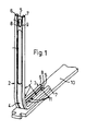
- an angular guide channel 1 which serves to train and pressure-rigid sliding receiving a flexurally elastic deflection at Eckumlenkungen for espagnolettes.
- This guide channel 1 has two right angles to each other directed, straight legs 2 and 3, which are integrally connected to each other by an arcuate portion 4.
- the guide channel 1 is made of a metal profile, in particular a brass profile, in which integrally connected to a substantially flat web portion 5 on both sides of two cross-sectionally C-shaped, with their open side opposing edge flanges 6 and 7 (Fig. 2) ,
- the edge flanges 6 and 7 are each formed by so-called curls on the longitudinal edges of a flat metal strip, which is then formed by forming the arcuate portion 4 to the angular guide channel 1.
- the guide channel 1 is fixed with its straight leg 3 on a cover or face plate 10, for example, directly by punctiform weld or solder joints 11 or by a clinching.
- the cover or faceplate 10 is not shown holes and this passing fasteners, e.g. Screws, connectable to the sash profile.
- the clear height 12 of the metal profile is about twice as large as the thickness 13 of serving for the production of the guide channel 1 strip material dimensioned. As a result, however, this clear height 12 of the profile is greater than the total thickness 14 of the guide channel 1 slidably accommodated, bending elastic deflecting member 15, which is formed for example of four superimposed, thin spring steel strips.
- the difference between the total thickness 14 of the deflecting member 15 and the clear height 12 of the profile cross section in the guide channel 1 can not be noticeable as excessively large slip, are in the metal profile of the guide channel 1 respectively in the two transition areas between the flat web portion 5 and the C. -shaped edge flanges 6 and 7 longitudinally extending beads 8 and 9 formed, preferably over the entire length of the metal profile continuously. These beads 8 and 9 project to the height 16 in the clear profile cross-section of the guide channel 1, so that the effective for the deflection member 15 profile cross-section 17 is correspondingly smaller than the clear height 12 of the profile cross-section.
- the height 16 of the clear profile cross section narrowing bead portion is suitably about half as large as the difference between the total thickness 14 of the deflecting member 15 and the clear height 12 of the profile cross-section.
- the fixing device 20 is arranged on the guide channel 1 and serves for the provisional fixing of the corner deflection 19 on the wing (not shown) during assembly, as described for example in DE 196 46 988 A1.
- the fixing device 20 according to FIG. 2 consists of a clamping spring 21 to be fastened to the guide channel 1, which can be connected to the guide channel 1 via a latching snap connection.
- the clamping spring 21 has the formation of the snap-snap connection a U-shaped cross-section, wherein the U-legs 22, 23 are formed approximately sinusoidal.
- the width of the guide channel 1 thereby exceeds that in the region of the sinusoidal curve legs 22, 23 between these minimally adjusting measures 27.
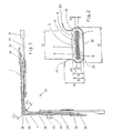
- the corner drive 19 is in addition to the guide channel 1, the deflecting member 15 and the cover angle 28 of one or more Driving rods 29 and guide pieces 30.
- the guide pieces 30 serve the longitudinally displaceable guide of the drive rods 29, which has a coupling shoe 31 and an overlap connection 32 for coupling with adjacent fitting parts. At the same time serve the guide pieces 30 for attachment of the guide channel 1 at the cover angle.
- At the corner deflection 27 while locking elements 33 may be provided. Holes for - not shown here - fixing screws are provided in the region of the guide pieces 30.
- the corner drive 19 is finally connected via these mounting screws with the casement profile.
- the clamping spring 21 is arranged in the region of the arcuate portion 4 of the guide channel 1 and projects, due to its height 35 (FIG. 2) of the legs 22, 23, into the laterally open region 36 between the guide channel 1 and the cover angle 28.
- the width 37 of the mounted on the guide channel 1 clamping spring 21 does not exceed the minimum dimension of Beschlagagenut.
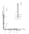
- the drive rod fitting with the Eckumlenkung of Fig. 4 and 5 shows another embodiment of the fixing device 20.
- the guide channel 1 is also integrally formed from a metal strip, in addition to the two longitudinal sides integrally adjoining C-shaped edge flanges 6,7 but provided that partially outwardly deformed edge flanges 40,41 form the fixing device 20.
- the partially interrupted edge flanges 6.7 in this area are not completely rolled inward but - relative to the other width 42 of the guide channel 1 - bulging slightly outward.
- the guide channel 1 in the region of the outwardly deformed edge flange 40, 41 has a trapezoidal U-shaped cross-section, since the U-legs 43, 44 run in antiparallel fashion.
- the fixing device 20 is located in the transition region of the arcuate section 4 to the limbs 2,3 thereof integrally therewith.
- the fixation is therefore not in the transition region of Betschagenuten but in each groove individually.
- FIG. 6 shows a corner drive 19 according to FIGS. 3 and 5, in which the guide channel 1 is likewise formed from a metal strip.
- the guide channel 1 has in its flat web part 5 (FIG. 2) on the rear side a laterally open bead 50, through which a fixing device 20 forming clamping plate 51 can be inserted transversely to the guide channel 1.
- the width of the bead 50 is matched to the lying between the beads 8 and 9 section.
- the bead 50 may be provided in the production of the guide channel 1 in the punch bending tool or be introduced later.
- the bead 50 is dimensioned so that the clamping plate 51 is inserted with its narrow side 53 However, the depth of the bead 50 is dimensioned only slightly larger than the thickness of the clamping plate 51. Since the bead 50 is closed in its longitudinal extent, the clamping plate 51 can be fixed by a slight deflection of the bead bottom 52. An escape of the clamping plate 51 is not possible by the U-shaped embrace of the clamping plate
- the clamping plate 51 consists of a flat, leaf-spring-like elongated strip, as shown in FIG. 7.
- the narrow sides 53 are rounded or chamfered, which facilitates the insertion of the clamping spring 51 in the lateral openings of the bead 50, but also prevents tilting or entanglement of the clamping spring 51 during insertion or possibly necessary longitudinal displacement of the corner on the wing.
- the bead 50 and thus the fixing device 20 is arranged in the region of the circular portion 4, since the clamping spring 51 otherwise can not dive sufficiently deep into the Betschagenut.
- the guide channel 1 can of course also be made as a molded part, for example made of plastic.
- the said fixing devices 20 can also be provided integrally on a guide channel produced in this way, preferably in one piece.
Landscapes
- Engineering & Computer Science (AREA)
- Mechanical Engineering (AREA)
- Clamps And Clips (AREA)
- Joining Of Corner Units Of Frames Or Wings (AREA)
- Power-Operated Mechanisms For Wings (AREA)
- Mutual Connection Of Rods And Tubes (AREA)
Claims (14)
- Crémone avec renvoi d'angle (19) pour tringles de manoeuvre guidées dans une rainure de réception périphérique de l'ouvrant,
qui sont accouplées entre elles à l'angle de l'ouvrant par un organe de renvoi (15) en lames de ressort,
qui est guidé dans un canal de guidage (1) angulaire, disposé dans la rainure de réception,
dans laquelle au moins une cornière de recouvrement (28) ou une barre de recouvrement (10), externe, masquant la rainure de réception peut être assemblée au profilé de l'ouvrant,
dans laquelle le canal de guidage (1) est fixé à la cornière (28) ou la barre (10) de recouvrement,
et dans laquelle le renvoi d'angle (19) peut être fixé par l'intermédiaire d'un dispositif de fixation (20), par emboîtement et/ou par friction, aux parois latérales de la rainure de réception,
caractérisée en ce que
la fixation par emboîtement et/ou par friction est produite par un dispositif de fixation (20) agencé dans le canal de guidage (1). - Crémone à renvoi d'angle selon la revendication 1,
caractérisée en ce que
le dispositif de fixation (20) est réalisé d'une pièce avec le canal de guidage (1). - Crémone à renvoi d'angle selon la revendication 1,
caractérisée en ce que
le dispositif de fixation (20) se compose d'un ressort de serrage (21) à fixer au canal de guidage (1), qui peut être assemblé au canal de guidage (1) par liaison par emboîtement-pression. - Crémone à renvoi d'angle selon la revendication 3,
caractérisée en ce que
le ressort de serrage (21) présente une section transversale en U, et les branches (22, 23) du U ont une forme approximativement sinusoïdale. - Crémone à renvoi d'angle selon la revendication 3 ou 4,
caractérisée en ce que
le ressort de serrage (21) peut être inséré à partir du milieu du rayon de la section (4) courbe du canal de guidage (1). - Crémone à renvoi d'angle selon l'une des revendications 3 à 5,
caractérisée en ce que
le ressort de serrage (21) est fabriqué en acier à ressort. - Crémone à renvoi d'angle selon la revendication 1, dans laquelle le canal de guidage (1) est formé à partir d'une bande métallique, en particulier une bande de laiton, dans laquelle deux rebords latéraux (6, 7) en C, dont les côtés ouverts sont dirigés l'un vers l'autre se raccordent d'une pièce aux deux faces longitudinales d'une âme (5) de section sensiblement plate, lesquels rebords sont formés par laminage et engagent l'organe de renvoi (15),
caractérisée en ce que
le dispositif de fixation (20) se compose d'au moins un rebord latéral (6, 7) déformé par section vers l'extérieur. - Crémone à renvoi d'angle selon la revendication 7,
caractérisée en ce que
le canal de guidage (1) présente une section en U dans la région du rebord latéral (6, 7) déformé vers l'extérieur, dont les branches du U (43, 44) s'étendent de manière anti-parallèle. - Crémone à renvoi d'angle selon la revendication 7 ou 8,
caractérisée en ce que
le dispositif de fixation (20) se trouve dans la zone de transition de la section (4) courbe avec les branches (2, 3) droites, qui s'y raccordent d'une pièce. - Crémone à renvoi d'angle selon la revendication 1, dans laquelle le canal de guidage (1) est formé à partir d'une bande métallique, en particulier une bande de laiton, dans laquelle deux rebords latéraux (6, 7) en C, dont les côtés ouverts sont dirigés l'un vers l'autre, se raccordent d'une pièce aux deux faces longitudinales d'une âme (5) de section sensiblement plate, lesquels rebords sont formés par laminage et engagent l'organe de renvoi (15),
caractérisée en ce que
le canal de guidage (1) présente au dos de son âme (5) plate une nervure (50) ouverte latéralement vers les bords longitudinaux, dans laquelle peut être insérée, perpendiculairement au canal de guidage (1), une lame de serrage (51) formant le dispositif de fixation (20). - Crémone à renvoi d'angle selon la revendication 10,
caractérisée en ce que
la lame de serrage (51) est constituée d'une bande plate du type lame de ressort. - Crémone à renvoi d'angle selon la revendication 10 ou 11,
caractérisée en ce que
la lame de serrage (51) présente des côtés étroits (53) arrondis ou chanfreinés. - Crémone à renvoi d'angle selon l'une des revendications 10 à 12,
caractérisée en ce que
la nervure (50) est disposée dans la région de la section (4) courbe. - Crémone à renvoi d'angle selon 1'une des revendications 10 à 13,
caractérisée en ce que
la nervure (50) présente une profondeur qui n'est que peu supérieure à l'épaisseur de la lame de serrage (51).
Applications Claiming Priority (3)
| Application Number | Priority Date | Filing Date | Title |
|---|---|---|---|
| DE19834038A DE19834038C2 (de) | 1998-07-29 | 1998-07-29 | Treibstangenbeschlag mit Eckumlenkung |
| DE19834038 | 1998-07-29 | ||
| PCT/EP1999/003804 WO2000006862A1 (fr) | 1998-07-29 | 1999-06-02 | Garniture de bielles motrices avec renvoi d'angle |
Publications (2)
| Publication Number | Publication Date |
|---|---|
| EP1101008A1 EP1101008A1 (fr) | 2001-05-23 |
| EP1101008B1 true EP1101008B1 (fr) | 2006-11-15 |
Family
ID=7875632
Family Applications (1)
| Application Number | Title | Priority Date | Filing Date |
|---|---|---|---|
| EP99927834A Expired - Lifetime EP1101008B1 (fr) | 1998-07-29 | 1999-06-02 | Garniture de bielles motrices avec renvoi d'angle |
Country Status (6)
| Country | Link |
|---|---|
| EP (1) | EP1101008B1 (fr) |
| AT (1) | ATE345433T1 (fr) |
| DE (2) | DE19834038C2 (fr) |
| HU (1) | HU224023B1 (fr) |
| PL (1) | PL193889B1 (fr) |
| WO (1) | WO2000006862A1 (fr) |
Cited By (1)
| Publication number | Priority date | Publication date | Assignee | Title |
|---|---|---|---|---|
| DE202008014353U1 (de) | 2008-10-29 | 2009-01-15 | Aug. Winkhaus Gmbh & Co. Kg | Eckumlenkung für einen Treibstangenbeschlag eines Fensters |
Families Citing this family (4)
| Publication number | Priority date | Publication date | Assignee | Title |
|---|---|---|---|---|
| DE10145882A1 (de) * | 2001-09-18 | 2003-04-03 | Winkhaus Fa August | Eckumlenkung für einen Treibstangenbeschlag |
| EP1577478B9 (fr) * | 2004-03-18 | 2013-07-10 | HAUTAU GmbH | Renvoi d'angle avec pièces de guidage |
| DE102007053340A1 (de) * | 2007-11-08 | 2009-05-14 | Aug. Winkhaus Gmbh & Co. Kg | Eckumlenkung für ein Treibstangenbeschlagsystem für einen Fenster- oder Türflügel |
| EP4056796B1 (fr) * | 2021-03-08 | 2024-08-14 | Mila Beslag A/S | Système à utiliser dans une fenêtre |
Family Cites Families (11)
| Publication number | Priority date | Publication date | Assignee | Title |
|---|---|---|---|---|
| NL7104154A (fr) * | 1970-04-02 | 1971-10-05 | ||
| DE2941631C2 (de) * | 1979-10-13 | 1985-06-20 | Siegenia-Frank Kg, 5900 Siegen | Eckumlenkung für Treibstangenbeschläge |
| DE8103368U1 (de) * | 1981-02-09 | 1981-06-19 | Siegenia-Frank Kg, 5900 Siegen | Drehkippfenster oder -tür |
| DE3216177C2 (de) | 1982-04-30 | 1985-01-10 | Top - element Bauelemente für Innenausbau + Raumgestaltung GmbH & Co KG, 4700 Hamm | Treibstangenbeschlag mit einer Eckumlenkung für in einer am Flügelrahmen umlaufenden Nut geführte Treibstangen |
| DE3729215C1 (de) | 1987-09-02 | 1989-04-27 | Siegenia Frank Kg | Stulpschienen-Eckverbindung |
| DE8815101U1 (de) * | 1988-12-03 | 1989-01-26 | Siegenia-Frank Kg, 5900 Siegen | Eckumlenkung von Treibstangenbeschlägen für Fenster, Türen od.dgl. |
| DE9100033U1 (de) * | 1991-01-03 | 1992-04-30 | Siegenia-Frank Kg, 5900 Siegen | Treibstangenbeschlag für Fenster, Türen o.dgl. |
| DE4138741C2 (de) * | 1991-11-26 | 1995-02-02 | Bilstein August Gmbh Co Kg | Befestigung für eine Beschlags-Eckumlenkung |
| DE9203338U1 (de) * | 1992-03-12 | 1993-07-08 | Siegenia-Frank Kg, 5900 Siegen | Treibstange für Fenster- und Türbeschläge, insbesondere Treibstangen-Kupplungsstück für Beschlags-Bauteile sowie mit einem solchen Treibstangen-Kupplungsstück ausgestattetes Beschlags-Bauteil |
| DE19525805C1 (de) * | 1995-07-15 | 1997-01-30 | Weidtmann Wilhelm Kg | Eckumlenkung von Treibstangen-Beschlägen für Fenster, Türen od. dgl. |
| DE19646988C5 (de) | 1996-11-14 | 2014-07-03 | Roto Frank Ag | Beschlag für ein Fenster |
-
1998
- 1998-07-29 DE DE19834038A patent/DE19834038C2/de not_active Expired - Fee Related
-
1999
- 1999-06-02 DE DE59913985T patent/DE59913985D1/de not_active Expired - Lifetime
- 1999-06-02 AT AT99927834T patent/ATE345433T1/de active
- 1999-06-02 EP EP99927834A patent/EP1101008B1/fr not_active Expired - Lifetime
- 1999-06-02 PL PL99345533A patent/PL193889B1/pl unknown
- 1999-06-02 HU HU0104925A patent/HU224023B1/hu not_active IP Right Cessation
- 1999-06-02 WO PCT/EP1999/003804 patent/WO2000006862A1/fr not_active Ceased
Cited By (1)
| Publication number | Priority date | Publication date | Assignee | Title |
|---|---|---|---|---|
| DE202008014353U1 (de) | 2008-10-29 | 2009-01-15 | Aug. Winkhaus Gmbh & Co. Kg | Eckumlenkung für einen Treibstangenbeschlag eines Fensters |
Also Published As
| Publication number | Publication date |
|---|---|
| DE59913985D1 (de) | 2006-12-28 |
| HUP0104925A2 (hu) | 2002-04-29 |
| PL193889B1 (pl) | 2007-03-30 |
| DE19834038A1 (de) | 2000-02-10 |
| DE19834038C2 (de) | 2002-09-19 |
| HU224023B1 (hu) | 2005-05-30 |
| EP1101008A1 (fr) | 2001-05-23 |
| HUP0104925A3 (en) | 2003-01-28 |
| WO2000006862A1 (fr) | 2000-02-10 |
| PL345533A1 (en) | 2001-12-17 |
| ATE345433T1 (de) | 2006-12-15 |
Similar Documents
| Publication | Publication Date | Title |
|---|---|---|
| DE4309088A1 (de) | Ortsfest einbaubare Scheibe für Kraftfahrzeuge | |
| AT404380B (de) | Vorrichtung, insbesondere distanzanker für justierung und befestigung von rahmen | |
| EP2868856B1 (fr) | Raccord d'angle destiné à relier des profilés creux coupés en onglet d'un cadre de porte ou de fenêtre | |
| DE69735867T2 (de) | Verbesserte ohrlose Klemme mit flachem Profil | |
| WO2019011978A1 (fr) | Connecteur, système composé d'un connecteur et d'une tige d'encliquetage contenant une tête d'un deuxième composant, procédé utilisant un tel système | |
| EP2754805B1 (fr) | Tringle de verrouillage pour une crémone | |
| CH663983A5 (de) | Treibstangenbeschlag fuer fenster oder tueren. | |
| EP1101008B1 (fr) | Garniture de bielles motrices avec renvoi d'angle | |
| WO2013087375A1 (fr) | Élément de fixation et grille latérale | |
| EP2058463B1 (fr) | Renvoi d'angle pour un système d'armature de tige motrice pour un vantail de fenêtre ou de porte | |
| EP0104340B1 (fr) | Agencement, en particulier pour une cloison de douche | |
| EP2754803B1 (fr) | Crémone de fenêtre ou de porte et tringle pour une telle crémone | |
| EP3953630A1 (fr) | Collier profilé pouvant être inséré de manière flexible | |
| DE19859546A1 (de) | Schieberstangenbefestigungs- und -führungselement | |
| DE2802037C3 (de) | Vorrichtung zum Zusammenhalten von an Luftkanalabschnitten sitzenden Verbindungsflanschen | |
| EP2754802A2 (fr) | Crémone de fenêtre ou de porte | |
| DE60108251T2 (de) | Schnellverbindungsstück | |
| DE2159244C3 (de) | Eckumlenkung für Treibstangenbeschläge | |
| DE202008011771U1 (de) | Dichtungsanordnung | |
| CH687716A5 (de) | Beschlag. | |
| DE8222539U1 (de) | Fenster- oder tuerfluegel | |
| DE19743121A1 (de) | Schellenanordnung zum Festklemmen eines Schlauches auf einem Rohrteil | |
| DE19839761A1 (de) | Treibstangenbeschlag mit Eckumlenkung | |
| EP1128010B1 (fr) | Ferrure pour une fenêtre ou une porte | |
| EP2177807A2 (fr) | Collier en bande |
Legal Events
| Date | Code | Title | Description |
|---|---|---|---|
| PUAI | Public reference made under article 153(3) epc to a published international application that has entered the european phase |
Free format text: ORIGINAL CODE: 0009012 |
|
| 17P | Request for examination filed |
Effective date: 20001115 |
|
| AK | Designated contracting states |
Kind code of ref document: A1 Designated state(s): AT BE CH DE DK ES FR GB IT LI NL |
|
| RBV | Designated contracting states (corrected) |
Designated state(s): AT BE CH DE DK ES FR GB IT LI NL |
|
| RIN1 | Information on inventor provided before grant (corrected) |
Inventor name: SASSMANNSHAUSEN, JUERGEN Inventor name: ROTGER STEIGEMANN, CARMEN Inventor name: LOHMANN, CORD Inventor name: GERSDORF, OLIVER |
|
| RAP1 | Party data changed (applicant data changed or rights of an application transferred) |
Owner name: SIEGENIA-AUBI KG |
|
| RAP1 | Party data changed (applicant data changed or rights of an application transferred) |
Owner name: SIEGENIA-AUBI KG |
|
| RAP1 | Party data changed (applicant data changed or rights of an application transferred) |
Owner name: SIEGENIA-AUBI KG |
|
| GRAP | Despatch of communication of intention to grant a patent |
Free format text: ORIGINAL CODE: EPIDOSNIGR1 |
|
| GRAS | Grant fee paid |
Free format text: ORIGINAL CODE: EPIDOSNIGR3 |
|
| GRAA | (expected) grant |
Free format text: ORIGINAL CODE: 0009210 |
|
| AK | Designated contracting states |
Kind code of ref document: B1 Designated state(s): AT BE CH DE DK ES FR GB IT LI NL |
|
| PG25 | Lapsed in a contracting state [announced via postgrant information from national office to epo] |
Ref country code: NL Free format text: LAPSE BECAUSE OF FAILURE TO SUBMIT A TRANSLATION OF THE DESCRIPTION OR TO PAY THE FEE WITHIN THE PRESCRIBED TIME-LIMIT Effective date: 20061115 Ref country code: IT Free format text: LAPSE BECAUSE OF FAILURE TO SUBMIT A TRANSLATION OF THE DESCRIPTION OR TO PAY THE FEE WITHIN THE PRESCRIBED TIME-LIMIT;WARNING: LAPSES OF ITALIAN PATENTS WITH EFFECTIVE DATE BEFORE 2007 MAY HAVE OCCURRED AT ANY TIME BEFORE 2007. THE CORRECT EFFECTIVE DATE MAY BE DIFFERENT FROM THE ONE RECORDED. Effective date: 20061115 |
|
| REG | Reference to a national code |
Ref country code: GB Ref legal event code: FG4D Free format text: NOT ENGLISH |
|
| GBT | Gb: translation of ep patent filed (gb section 77(6)(a)/1977) |
Effective date: 20061115 |
|
| REG | Reference to a national code |
Ref country code: CH Ref legal event code: EP |
|
| REF | Corresponds to: |
Ref document number: 59913985 Country of ref document: DE Date of ref document: 20061228 Kind code of ref document: P |
|
| PG25 | Lapsed in a contracting state [announced via postgrant information from national office to epo] |
Ref country code: DK Free format text: LAPSE BECAUSE OF FAILURE TO SUBMIT A TRANSLATION OF THE DESCRIPTION OR TO PAY THE FEE WITHIN THE PRESCRIBED TIME-LIMIT Effective date: 20070215 |
|
| PG25 | Lapsed in a contracting state [announced via postgrant information from national office to epo] |
Ref country code: ES Free format text: LAPSE BECAUSE OF FAILURE TO SUBMIT A TRANSLATION OF THE DESCRIPTION OR TO PAY THE FEE WITHIN THE PRESCRIBED TIME-LIMIT Effective date: 20070226 |
|
| ET | Fr: translation filed | ||
| NLV1 | Nl: lapsed or annulled due to failure to fulfill the requirements of art. 29p and 29m of the patents act | ||
| PLBE | No opposition filed within time limit |
Free format text: ORIGINAL CODE: 0009261 |
|
| STAA | Information on the status of an ep patent application or granted ep patent |
Free format text: STATUS: NO OPPOSITION FILED WITHIN TIME LIMIT |
|
| 26N | No opposition filed |
Effective date: 20070817 |
|
| REG | Reference to a national code |
Ref country code: CH Ref legal event code: PL |
|
| PG25 | Lapsed in a contracting state [announced via postgrant information from national office to epo] |
Ref country code: LI Free format text: LAPSE BECAUSE OF NON-PAYMENT OF DUE FEES Effective date: 20070630 Ref country code: CH Free format text: LAPSE BECAUSE OF NON-PAYMENT OF DUE FEES Effective date: 20070630 |
|
| PGFP | Annual fee paid to national office [announced via postgrant information from national office to epo] |
Ref country code: GB Payment date: 20080630 Year of fee payment: 10 |
|
| PGFP | Annual fee paid to national office [announced via postgrant information from national office to epo] |
Ref country code: BE Payment date: 20080701 Year of fee payment: 10 |
|
| BERE | Be: lapsed |
Owner name: *SIEGENIA-AUBI K.G. Effective date: 20090630 |
|
| GBPC | Gb: european patent ceased through non-payment of renewal fee |
Effective date: 20090602 |
|
| PG25 | Lapsed in a contracting state [announced via postgrant information from national office to epo] |
Ref country code: GB Free format text: LAPSE BECAUSE OF NON-PAYMENT OF DUE FEES Effective date: 20090602 |
|
| PG25 | Lapsed in a contracting state [announced via postgrant information from national office to epo] |
Ref country code: BE Free format text: LAPSE BECAUSE OF NON-PAYMENT OF DUE FEES Effective date: 20090630 |
|
| REG | Reference to a national code |
Ref country code: FR Ref legal event code: PLFP Year of fee payment: 18 |
|
| REG | Reference to a national code |
Ref country code: FR Ref legal event code: PLFP Year of fee payment: 19 |
|
| PGFP | Annual fee paid to national office [announced via postgrant information from national office to epo] |
Ref country code: FR Payment date: 20170626 Year of fee payment: 19 |
|
| PGFP | Annual fee paid to national office [announced via postgrant information from national office to epo] |
Ref country code: AT Payment date: 20170627 Year of fee payment: 19 |
|
| PGFP | Annual fee paid to national office [announced via postgrant information from national office to epo] |
Ref country code: DE Payment date: 20170630 Year of fee payment: 19 Ref country code: IT Payment date: 20170630 Year of fee payment: 19 |
|
| REG | Reference to a national code |
Ref country code: DE Ref legal event code: R119 Ref document number: 59913985 Country of ref document: DE |
|
| REG | Reference to a national code |
Ref country code: AT Ref legal event code: MM01 Ref document number: 345433 Country of ref document: AT Kind code of ref document: T Effective date: 20180602 |
|
| PG25 | Lapsed in a contracting state [announced via postgrant information from national office to epo] |
Ref country code: AT Free format text: LAPSE BECAUSE OF NON-PAYMENT OF DUE FEES Effective date: 20180602 Ref country code: IT Free format text: LAPSE BECAUSE OF NON-PAYMENT OF DUE FEES Effective date: 20180602 Ref country code: FR Free format text: LAPSE BECAUSE OF NON-PAYMENT OF DUE FEES Effective date: 20180630 Ref country code: DE Free format text: LAPSE BECAUSE OF NON-PAYMENT OF DUE FEES Effective date: 20190101 |