EP1101049B1 - Getriebegehäuse - Google Patents
Getriebegehäuse Download PDFInfo
- Publication number
- EP1101049B1 EP1101049B1 EP99924487A EP99924487A EP1101049B1 EP 1101049 B1 EP1101049 B1 EP 1101049B1 EP 99924487 A EP99924487 A EP 99924487A EP 99924487 A EP99924487 A EP 99924487A EP 1101049 B1 EP1101049 B1 EP 1101049B1
- Authority
- EP
- European Patent Office
- Prior art keywords
- backwall
- gear housing
- central portion
- housing
- gear
- Prior art date
- Legal status (The legal status is an assumption and is not a legal conclusion. Google has not performed a legal analysis and makes no representation as to the accuracy of the status listed.)
- Expired - Lifetime
Links
Images


Classifications
-
- F—MECHANICAL ENGINEERING; LIGHTING; HEATING; WEAPONS; BLASTING
- F16—ENGINEERING ELEMENTS AND UNITS; GENERAL MEASURES FOR PRODUCING AND MAINTAINING EFFECTIVE FUNCTIONING OF MACHINES OR INSTALLATIONS; THERMAL INSULATION IN GENERAL
- F16H—GEARING
- F16H57/00—General details of gearing
- F16H57/02—Gearboxes; Mounting gearing therein
- F16H57/039—Gearboxes for accommodating worm gears
-
- E—FIXED CONSTRUCTIONS
- E05—LOCKS; KEYS; WINDOW OR DOOR FITTINGS; SAFES
- E05F—DEVICES FOR MOVING WINGS INTO OPEN OR CLOSED POSITION; CHECKS FOR WINGS; WING FITTINGS NOT OTHERWISE PROVIDED FOR, CONCERNED WITH THE FUNCTIONING OF THE WING
- E05F15/00—Power-operated mechanisms for wings
- E05F15/60—Power-operated mechanisms for wings using electrical actuators
- E05F15/603—Power-operated mechanisms for wings using electrical actuators using rotary electromotors
- E05F15/665—Power-operated mechanisms for wings using electrical actuators using rotary electromotors for vertically-sliding wings
- E05F15/689—Power-operated mechanisms for wings using electrical actuators using rotary electromotors for vertically-sliding wings specially adapted for vehicle windows
- E05F15/697—Motor units therefor, e.g. geared motors
-
- F—MECHANICAL ENGINEERING; LIGHTING; HEATING; WEAPONS; BLASTING
- F16—ENGINEERING ELEMENTS AND UNITS; GENERAL MEASURES FOR PRODUCING AND MAINTAINING EFFECTIVE FUNCTIONING OF MACHINES OR INSTALLATIONS; THERMAL INSULATION IN GENERAL
- F16H—GEARING
- F16H1/00—Toothed gearings for conveying rotary motion
- F16H1/02—Toothed gearings for conveying rotary motion without gears having orbital motion
- F16H1/04—Toothed gearings for conveying rotary motion without gears having orbital motion involving only two intermeshing members
- F16H1/12—Toothed gearings for conveying rotary motion without gears having orbital motion involving only two intermeshing members with non-parallel axes
- F16H1/16—Toothed gearings for conveying rotary motion without gears having orbital motion involving only two intermeshing members with non-parallel axes comprising worm and worm-wheel
-
- F—MECHANICAL ENGINEERING; LIGHTING; HEATING; WEAPONS; BLASTING
- F16—ENGINEERING ELEMENTS AND UNITS; GENERAL MEASURES FOR PRODUCING AND MAINTAINING EFFECTIVE FUNCTIONING OF MACHINES OR INSTALLATIONS; THERMAL INSULATION IN GENERAL
- F16H—GEARING
- F16H57/00—General details of gearing
- F16H57/02—Gearboxes; Mounting gearing therein
- F16H57/032—Gearboxes; Mounting gearing therein characterised by the materials used
-
- E—FIXED CONSTRUCTIONS
- E05—LOCKS; KEYS; WINDOW OR DOOR FITTINGS; SAFES
- E05Y—INDEXING SCHEME ASSOCIATED WITH SUBCLASSES E05D AND E05F, RELATING TO CONSTRUCTION ELEMENTS, ELECTRIC CONTROL, POWER SUPPLY, POWER SIGNAL OR TRANSMISSION, USER INTERFACES, MOUNTING OR COUPLING, DETAILS, ACCESSORIES, AUXILIARY OPERATIONS NOT OTHERWISE PROVIDED FOR, APPLICATION THEREOF
- E05Y2900/00—Application of doors, windows, wings or fittings thereof
- E05Y2900/50—Application of doors, windows, wings or fittings thereof for vehicles
- E05Y2900/53—Type of wing
- E05Y2900/55—Windows
-
- F—MECHANICAL ENGINEERING; LIGHTING; HEATING; WEAPONS; BLASTING
- F16—ENGINEERING ELEMENTS AND UNITS; GENERAL MEASURES FOR PRODUCING AND MAINTAINING EFFECTIVE FUNCTIONING OF MACHINES OR INSTALLATIONS; THERMAL INSULATION IN GENERAL
- F16H—GEARING
- F16H57/00—General details of gearing
- F16H57/02—Gearboxes; Mounting gearing therein
- F16H2057/02039—Gearboxes for particular applications
- F16H2057/02082—Gearboxes for particular applications for application in vehicles other than propelling, e.g. adjustment of parts
-
- F—MECHANICAL ENGINEERING; LIGHTING; HEATING; WEAPONS; BLASTING
- F16—ENGINEERING ELEMENTS AND UNITS; GENERAL MEASURES FOR PRODUCING AND MAINTAINING EFFECTIVE FUNCTIONING OF MACHINES OR INSTALLATIONS; THERMAL INSULATION IN GENERAL
- F16H—GEARING
- F16H57/00—General details of gearing
- F16H57/02—Gearboxes; Mounting gearing therein
- F16H57/021—Shaft support structures, e.g. partition walls, bearing eyes, casing walls or covers with bearings
- F16H2057/0213—Support of worm gear shafts
-
- Y—GENERAL TAGGING OF NEW TECHNOLOGICAL DEVELOPMENTS; GENERAL TAGGING OF CROSS-SECTIONAL TECHNOLOGIES SPANNING OVER SEVERAL SECTIONS OF THE IPC; TECHNICAL SUBJECTS COVERED BY FORMER USPC CROSS-REFERENCE ART COLLECTIONS [XRACs] AND DIGESTS
- Y10—TECHNICAL SUBJECTS COVERED BY FORMER USPC
- Y10T—TECHNICAL SUBJECTS COVERED BY FORMER US CLASSIFICATION
- Y10T74/00—Machine element or mechanism
- Y10T74/21—Elements
- Y10T74/2186—Gear casings
Definitions
- the field of invention is gear housings, more particularly gear housings for a motor vehicle window lift drive.
- a rotatably driven worm drive shaft engages a toothed gear, such as a worm wheel, disposed in a gear housing.
- the worm wheel has an output shaft with one end extending radially through the gear housing for rotatably driving a window lift mechanism.
- An opposite end of the output shaft extends radially into a backwall of the gear housing.
- the backwall supports the output shaft by counteracting forces exerted onto the backwall by the output shaft.
- the output shaft transmits radial and tangential forces developed at the worm wheel toothing and worm drive shaft interface. These forces are absorbed by the backwall by various means and methods.
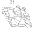
- One known housing provides sufficient structural integrity in the housing backwall by providing a thickened backwall wall.
- a thickened plastic or metal housing adds unnecessary weight to the overall mechanism and requires a greater amount of material to fabricate than other alternatives.
- Another known housing incorporates strengthening ribs in the backwall to provide support and structural integrity in key locations.
- This housing requires less material and ,therefore, provides a lighter housing that is less expensive to produce than the method described above.
- the ribs require fabrication of the housing with varying wall thicknesses that concentrate stresses increasing the potential for fatigue failure and require looser fabrication tolerances increasing material requirements.
- the present invention provides an improved gear housing backwall as defined by the features of claim 1 for use in a worm gear drive mechanism having an output shaft.
- the housing has an integral backwall adapted to support the output shaft of the drive mechanism.
- the backwall has a cylindrical central portion for receiving one end of the output shaft.
- a plurality of equal annulus segments extend radially from the central portion providing support for the central portion in tension and compression. Each segment has a narrow end, a wide end, and sides. The narrow end of adjacent segments alternately form an integral part of the central portion above and below a plane orthogonal to a central axis of the central portion. The wide end of each segment converges on the plane at the backwall periphery.
- a general objective of the present invention is to provide a plastic gear housing having a backwall that supports the output shaft without requiring excess plastic material for structural integrity.
- the housing backwall of the present invention is formed with a substantially uniform wall thickness that does not require thicker wall sections to adequately support the output shaft.
- Another objective of the present invention is to provide a plastic gear housing that requires less material to fabricate.
- the housing backwall of the present invention having a substantially uniform wall thickness can be fabricated to tighter tolerances reducing the material required to fabricate the article.
- Yet another objective of the present invention is to provide an improved gear housing that is less susceptible to fatigue failure than the prior art.
- the housing backwall of the present invention supports the output shaft with compression members that are less susceptible to fatigue than tension members found in the prior art.
- an embodiment of the present invention is a direct current motor vehicle window lift drive 10.
- the motor drive 10 has a worm drive shaft 12 disposed in a motor housing 14 that is flange mounted to a gear housing 16.
- the drive shaft 12 engages a worm wheel 18 press fit, or mounted by other methods known in the art, on an axially extending output shaft 20.
- the worm wheel 18 is adapted for rotatably driving a window lift mechanism (not shown) that raises and lowers an automobile window (not shown).
- the drive shaft 12 has a first end 22 disposed within the motor housing 14.
- the drive shaft first end 22 accommodates a laminated core of a rotor provided with a rotor (armature) winding.
- a drive shaft distal end 28 opposite the first end 22 extends into the gear housing 16 and is adapted to drive the worm wheel 18.
- the drive shaft 12 is rotatably mounted in the motor housing 14 by methods known in the art.
- a motor housing 14 and drive shaft 12 for use with the present invention are disclosed in U.S. Patent No. 5,517,070 .
- the gear housing 16 has a flange mounting portion 30 and a cavity 32.
- the gear housing 16 is polybutylene terepthalate having a glass fiber filler, such as Valox 420, available from GE Plastics, Pittsfield, MA or Celanex 7246 available from Ticona GmbH, Germany. Other materials exhibiting similar properties may be used without departing from the scope of the present invention.
- the housing 16 is preferably formed by injection molding or other methods known in the art.
- the flange mounting portion 30 is flange mounted to the motor housing 14 by screws 24, or the like, received by screw bosses 34 integrally formed part of the gear housing 16.
- the drive shaft distal end 28 extends into the gear housing cavity 32 through an opening 36 in the flange mounting portion 30.
- the opening 36 is adapted to receive a bushing 38 that radially supports the drive shaft 12.
- a breather passage 40 formed part of the flange mounting portion 30 receives a filter 42 and allows air to vent from the motor housing 14.
- the cup shaped cavity 32 of the gear housing 16 is integrally formed part of the flange mounting portion 30 and is defined by a sidewall 44 along the cavity periphery and a backwall 48 that supports the worm gear output shaft 20.
- the cavity 32 is generally circular and adapted to receive the rotatably mounted worm wheel 18 that tangentially engages the drive shaft 12.
- Supports 50 integrally formed part of the cavity sidewall 44 prevent excessive axial and radial movement of the drive shaft 12 in the gear housing 16.
- Through hole bosses 62 formed an integral part of the gear housing sidewall 44 provide attachment points for coupling the assembled motor vehicle window lift drive 10 to the window lift mechanism (not shown).
- the worm wheel 18 is press fit on an axially extending output shaft 20 and rotatably drives the window lift mechanism (not shown).
- the output shaft 20 has one end 52 supported by the backwall 48 and the opposite end 56 extending through an opening 57 in the housing cover 58 for engagement with the window lift mechanism (not shown).
- the housing cover 58 is mounted on the housing sidewall 44 by methods known in the art, such as press fitting or ultrasonic welding.
- a groove 60 formed in the housing sidewall 44 is adapted to receive the cover 58 and provide a seal that protects the components inside the window lift drive 10 from adverse conditions.
- the backwall 48 has a generally cylindrical central portion 64 for receiving the output shaft end 52 and a support portion 66 that is an integral part of the central portion 64.
- the central portion 64 has a cylindrical sidewall 68, an open top 70, a closed bottom 72, and a central axis 74.
- the output shaft end 52 is received in the open top 70 and supported axially by the closed bottom 72 and radially by the central portion sidewall 68.
- the central portion bottom 72 is closed in the preferred embodiment, an open bottom may also be used without departing from the present invention.
- the output shaft can be axially supported by a bushing or other methods known in the art.
- the backwall support portion 66 having a uniform wall thickness is formed by six annulus segments 76 that structurally support the central portion 64. Although six annulus segments are preferred, any number of annulus segments may be used without departing from the scope of the present invention.
- Each annulus segment 76 has a narrow end 78, a wide end 80, and sides 82. Looking particularly at Fig. 7, the narrow end 78 of adjacent segments 76 alternately form an integral part of the central portion 64 above and below a common plane 80 that is orthogonal to the central portion central axis 74. The segments 76 extend radially away from the central portion 64 toward the housing sidewall 44 converging on the common plane 85 to form the backwall periphery at the intersection of the segments 76 and the common plane 85.
- the sides 82 of adjacent segments 76 are joined by vertical sidewalls 84 providing additional structural support to the backwall 48.
- vertical sidewalls are shown and described, angled sidewalls may be used to join annulus segments that are narrower or wider than shown without departing from the scope of the present invention.
- the uniform wall thickness of the backwall 48 advantageously requires less material to fabricate than prior art rib designs. Additionally, tighter fabrication tolerances may be maintained during fabrication without wall thickness variations created by strengthening ribs.
- annular ridge 86 integrally formed part of the backwall 48 and concentric with the central portion central axis 74 provides a thrust bearing surface for the rotating worm wheel 18.
- the ridge 86 is a wear surface that is intended to wear away over time instead of the backwall 48, thus prolonging the useful life of the gear housing 16.
- the material characteristics of Valox. 420 and a backwall support portion nominal wall thickness of 2 mm were used in the calculations.
Landscapes
- Engineering & Computer Science (AREA)
- General Engineering & Computer Science (AREA)
- Mechanical Engineering (AREA)
- Gear Transmission (AREA)
- General Details Of Gearings (AREA)
- Valve-Gear Or Valve Arrangements (AREA)
- Dry Shavers And Clippers (AREA)
- Valve Device For Special Equipments (AREA)
- Power-Operated Mechanisms For Wings (AREA)
- Arrangement And Driving Of Transmission Devices (AREA)
- Applications Or Details Of Rotary Compressors (AREA)
- Vessels And Coating Films For Discharge Lamps (AREA)
- Gas-Filled Discharge Tubes (AREA)
- Superconductors And Manufacturing Methods Therefor (AREA)
Claims (9)
- Getriebegehäuserückwand (48), die Teil eines Getriebegehäuses (16) bildet, wobei die Rückwand (48) aufweist:Einen zentralen Abschnitt (64), der ein Ende (52) einer Welle (20) eines Zahnrads trägt, wobei der zentrale Abschnitt (64) eine Mittenachse (74) aufweist, die eine Ebene (85) senkrecht zu der Mittenachse (74) schneidet; undmehrere Ringsegmente, die den zentralen Abschnitt umgeben, wobei jedes der Segmente ein schmales Ende (78), ein breites Ende (80) und Seiten (82) aufweist, dadurch gekennzeichnet, dass schmale Enden (78) abwechselnder Segmente einen integralen Teil des zentralen Abschnitts (64) über der Ebene (85) bilden, und dass schmale Enden (78) von Segmenten benachbart zu den abwechselnden Segmenten einen integralen Teil des zentralen Abschnitts (64) unter der Ebene (85) bilden, und dass breite Enden (80) sämtliche Segmente auf der Ebene (85) konvergieren.
- Getriebegehäuserückwand nach Anspruch 1, wobei benachbarte Ringsegmente durch Seitenwände (84) verbunden sind.
- Getriebegehäuserückwand nach Anspruch 2, wobei die Seitenwände (84) im Wesentlichen parallel zu der Mittenachse (74) verlaufen.
- Getriebegehäuserückwand nach Anspruch 1, wobei das Gehäuse (16) aus Polybutylenterepthalat gebildet ist.
- Getriebegehäuserückwand nach Anspruch 1, wobei das Gehäuse (16) durch Spritzgießen gebildet ist.
- Getriebegehäuserückwand nach Anspruch 1, wobei die Rückwand (46) eine Ringrippe (86) aufweist.
- Getriebegehäuserückwand nach Anspruch 1, wobei die Rückwand (46) eine Wandnenndicke von nicht mehr als 2 mm aufweist.
- Getriebegehäuserückwand nach Anspruch 1, wobei das Zahnrad (18) ein Schneckenrad ist.
- Getriebegehäuserückwand nach Anspruch 1, wobei das Zahnrad (18) durch eine Schneckenantriebswelle (12) drehbar angetrieben ist.
Applications Claiming Priority (3)
| Application Number | Priority Date | Filing Date | Title |
|---|---|---|---|
| US09/095,736 US6014915A (en) | 1998-06-11 | 1998-06-11 | Gear housing |
| US95736 | 1998-06-11 | ||
| PCT/US1999/011479 WO1999064766A1 (en) | 1998-06-11 | 1999-05-25 | Gear housing |
Publications (2)
| Publication Number | Publication Date |
|---|---|
| EP1101049A1 EP1101049A1 (de) | 2001-05-23 |
| EP1101049B1 true EP1101049B1 (de) | 2007-10-24 |
Family
ID=22253362
Family Applications (1)
| Application Number | Title | Priority Date | Filing Date |
|---|---|---|---|
| EP99924487A Expired - Lifetime EP1101049B1 (de) | 1998-06-11 | 1999-05-25 | Getriebegehäuse |
Country Status (10)
| Country | Link |
|---|---|
| US (1) | US6014915A (de) |
| EP (1) | EP1101049B1 (de) |
| JP (1) | JP3554277B2 (de) |
| CN (1) | CN1105839C (de) |
| AT (1) | ATE376636T1 (de) |
| AU (1) | AU4097399A (de) |
| BR (1) | BR9911141A (de) |
| CA (1) | CA2334574C (de) |
| DE (2) | DE19983280T1 (de) |
| WO (1) | WO1999064766A1 (de) |
Families Citing this family (45)
| Publication number | Priority date | Publication date | Assignee | Title |
|---|---|---|---|---|
| US6371244B2 (en) * | 1995-03-13 | 2002-04-16 | Toshio Okamura | Escape device |
| DE19947620A1 (de) * | 1999-10-04 | 2001-04-05 | Valeo Auto Electric Gmbh | Wischeinrichtung |
| US6628026B2 (en) * | 2000-03-30 | 2003-09-30 | Asmo Co., Ltd. | Geared motor including ribbed gear housing |
| US6345678B1 (en) * | 2001-03-21 | 2002-02-12 | Shian-Pei Chang | Scooter |
| US7098562B2 (en) * | 2003-02-10 | 2006-08-29 | Siemens Vdo Automotive Corporation | Ambidextrous electronic window lift motor |
| US20040173051A1 (en) * | 2003-03-05 | 2004-09-09 | Sinka Aaron Alexander | Breather system for a housing containing a lubricant sump |
| US7258644B2 (en) * | 2003-06-30 | 2007-08-21 | Dana Corporation | Tandem axle carrier structural rib |
| DE10335014A1 (de) * | 2003-07-31 | 2005-02-24 | Robert Bosch Gmbh | Getriebe-Antriebseinheit |
| JP4472956B2 (ja) * | 2003-08-21 | 2010-06-02 | アスモ株式会社 | モータのギヤハウジング |
| USD528981S1 (en) * | 2004-07-26 | 2006-09-26 | Key Components, Inc. | Gear housing for an automotive starter motor |
| EP1744082B1 (de) | 2005-07-15 | 2011-06-29 | Brose Fahrzeugteile GmbH & Co. KG, Würzburg | Stellantrieb, insbesondere für ein Kraftfahrzeug |
| USD549731S1 (en) | 2005-10-20 | 2007-08-28 | Dana Corporation | Vehicle differential case |
| US7341536B2 (en) * | 2005-10-20 | 2008-03-11 | Dana Corporation | Light weight differential case half |
| JP2007329995A (ja) * | 2006-06-06 | 2007-12-20 | Asmo Co Ltd | モータ |
| JP4850606B2 (ja) | 2006-07-27 | 2012-01-11 | アスモ株式会社 | モータ及びワイパ装置 |
| DE102007009566B4 (de) | 2007-02-27 | 2021-07-22 | Robert Bosch Gmbh | Getriebe-Antriebseinheit mit gehäusefestem Lagerbolzen |
| JP4950921B2 (ja) * | 2008-03-13 | 2012-06-13 | 株式会社ミツバ | モータ装置 |
| DE102008039313A1 (de) * | 2008-08-22 | 2010-02-25 | Jäger Automobil- Technik GmbH & Co. KG | Motor-Getriebe-Antriebseinheit, insbesondere für Kraftfahrzeug-Verstellantriebe |
| DE102008041447B4 (de) | 2008-08-22 | 2021-12-09 | Robert Bosch Gmbh | Getriebe-Antriebseinheit |
| CN101942947A (zh) * | 2009-07-08 | 2011-01-12 | 德昌电机(深圳)有限公司 | 密封装置及应用该密封装置的车窗升降装置 |
| CN102859236B (zh) * | 2009-11-23 | 2016-08-17 | Gkn动力传动系统国际有限责任公司 | 排气装置和具有这种排气装置的传动装置 |
| DE102010007785A1 (de) * | 2010-02-12 | 2011-08-18 | MAHLE International GmbH, 70376 | Antriebsvorrichtung |
| WO2011114642A1 (ja) * | 2010-03-15 | 2011-09-22 | マブチモーター株式会社 | ウォームホイール、減速機および減速機付モータ |
| CN105162282B (zh) * | 2010-08-23 | 2019-01-04 | 株式会社美姿把 | 带减速机构的马达 |
| JP6111078B2 (ja) * | 2013-01-18 | 2017-04-05 | Ntn株式会社 | 電動リニアアクチュエータ |
| DE102013220444B4 (de) * | 2013-10-10 | 2015-07-09 | Robert Bosch Gmbh | Gehäuseelement für eine Getriebe-Antriebseinrichtung eines Komfortantriebes |
| DE102014103576B4 (de) | 2014-03-17 | 2018-04-05 | Robert Bosch Automotive Steering Gmbh | Gehäuse für lenkgetriebe |
| DE102014113496A1 (de) * | 2014-09-18 | 2016-03-24 | Getrag Getriebe- Und Zahnradfabrik Hermann Hagenmeyer Gmbh & Cie Kg | Gehäuseanordnung |
| USD774576S1 (en) * | 2015-04-20 | 2016-12-20 | SZ DJI Technology Co., Ltd. | Motor |
| CN106150260A (zh) * | 2016-08-15 | 2016-11-23 | 南通联科汽车零部件股份有限公司 | 齿轮箱 |
| US11766956B2 (en) | 2016-09-08 | 2023-09-26 | Fisher & Company, Incorporated | Open architecture power length adjuster assembly for a vehicle seat and method of manufacturing the same |
| US11273506B2 (en) | 2016-09-08 | 2022-03-15 | Fisher & Company, Incorporated | Open architecture power length adjuster assembly for a vehicle seat and method of manufacturing the same |
| WO2019087946A1 (ja) * | 2017-10-30 | 2019-05-09 | 日本精工株式会社 | 電動パワーステアリング装置用ギヤハウジングおよびその製造方法、並びに、電動パワーステアリング装置 |
| WO2019087945A1 (ja) * | 2017-10-30 | 2019-05-09 | 日本精工株式会社 | 電動パワーステアリング装置用ギヤハウジングおよびその製造方法、並びに、電動パワーステアリング装置 |
| US10677342B2 (en) | 2018-07-09 | 2020-06-09 | Robert Bosch Mexico Sistemas Automotrices S.A. de C.V. | Gear housing including snap-fit connection between housing cover and gear shaft |
| USD925633S1 (en) * | 2018-12-06 | 2021-07-20 | Logicdata Electronic & Software Entwicklungs Gmbh | Gearbox cover |
| CN113272172B (zh) | 2019-01-09 | 2023-06-27 | 费舍尔和同伴有限公司 | 动力座椅轨道组件 |
| US11760233B2 (en) | 2019-02-20 | 2023-09-19 | Fisher & Company, Incorporated | Ultra-compact power length adjuster with anti-back drive capability and pinion-rack output for a vehicle seat |
| USD953377S1 (en) * | 2020-03-09 | 2022-05-31 | Erae Ams Co., Ltd. | Seal for drive shaft of a vehicle |
| US11529892B2 (en) | 2020-05-01 | 2022-12-20 | Fisher & Company, Incorporated | Gearbox for vehicle seat adjustment mechanism |
| US11485255B2 (en) | 2020-05-01 | 2022-11-01 | Fisher & Company, Incorporated | Gearbox for vehicle seat adjustment mechanism |
| USD986824S1 (en) * | 2021-07-12 | 2023-05-23 | Walter Parsadayan | Gear box for a gate operator |
| US12496937B2 (en) | 2022-10-12 | 2025-12-16 | Fisher & Company, Incorporated | Vehicle seat adjustment system with power long rails |
| US12503016B2 (en) | 2022-10-12 | 2025-12-23 | Fisher & Company, Incorporated | Vehicle seat adjustment assembly with reduced-backlash gear system |
| USD1068674S1 (en) * | 2023-06-01 | 2025-04-01 | Timotion Technology Co., Ltd. | Motor assembly |
Family Cites Families (9)
| Publication number | Priority date | Publication date | Assignee | Title |
|---|---|---|---|---|
| US2477576A (en) * | 1949-08-02 | Axle housing | ||
| US1246930A (en) * | 1917-02-14 | 1917-11-20 | Arthur E Jenney | Adaptable motor and mounting. |
| US2478180A (en) * | 1946-01-14 | 1949-08-09 | Timken Axle Co Detroit | Convoluted axle housing member |
| GB1067164A (en) * | 1963-08-24 | 1967-05-03 | Aurora Gearing Company Wilmot | Improvements in speed-reduction gear-boxes |
| DE2915669A1 (de) * | 1979-04-18 | 1980-10-23 | Brose & Co Metallwerk Max | Elektrischer fensterheberantrieb fuer einen seilzug- oder gestaengefensterheber |
| DE3244621A1 (de) * | 1982-12-02 | 1984-06-07 | SWF-Spezialfabrik für Autozubehör Gustav Rau GmbH, 7120 Bietigheim-Bissingen | Antriebseinheit, insbesondere fuer scheibenwischer von kraftfahrzeugen |
| DE3429249A1 (de) * | 1984-08-08 | 1986-02-20 | Siemens AG, 1000 Berlin und 8000 München | Getriebeanordnung, insbesondere schneckengetriebeanordnung |
| US5287770A (en) * | 1992-11-25 | 1994-02-22 | Schiller-Pfeiffer, Inc. | Die cast transmission housing for rototiller |
| DE9313949U1 (de) * | 1993-09-15 | 1995-01-26 | Robert Bosch Gmbh, 70469 Stuttgart | Aggregat zum Verstellen von zu einem Kraftfahrzeug gehörenden Bauteilen zwischen zwei Endlagen |
-
1998
- 1998-06-11 US US09/095,736 patent/US6014915A/en not_active Expired - Lifetime
-
1999
- 1999-05-25 CN CN99808616A patent/CN1105839C/zh not_active Expired - Fee Related
- 1999-05-25 CA CA002334574A patent/CA2334574C/en not_active Expired - Fee Related
- 1999-05-25 JP JP2000553735A patent/JP3554277B2/ja not_active Expired - Fee Related
- 1999-05-25 DE DE19983280T patent/DE19983280T1/de not_active Withdrawn
- 1999-05-25 EP EP99924487A patent/EP1101049B1/de not_active Expired - Lifetime
- 1999-05-25 AU AU40973/99A patent/AU4097399A/en not_active Abandoned
- 1999-05-25 WO PCT/US1999/011479 patent/WO1999064766A1/en not_active Ceased
- 1999-05-25 AT AT99924487T patent/ATE376636T1/de not_active IP Right Cessation
- 1999-05-25 DE DE69937402T patent/DE69937402T2/de not_active Expired - Fee Related
- 1999-05-25 BR BR9911141-1A patent/BR9911141A/pt not_active IP Right Cessation
Also Published As
| Publication number | Publication date |
|---|---|
| JP3554277B2 (ja) | 2004-08-18 |
| CA2334574C (en) | 2005-01-25 |
| CN1105839C (zh) | 2003-04-16 |
| AU4097399A (en) | 1999-12-30 |
| CA2334574A1 (en) | 1999-12-16 |
| DE19983280T1 (de) | 2001-07-26 |
| DE69937402T2 (de) | 2008-07-24 |
| ATE376636T1 (de) | 2007-11-15 |
| BR9911141A (pt) | 2001-03-06 |
| US6014915A (en) | 2000-01-18 |
| WO1999064766A1 (en) | 1999-12-16 |
| CN1309750A (zh) | 2001-08-22 |
| DE69937402D1 (de) | 2007-12-06 |
| JP2002517694A (ja) | 2002-06-18 |
| EP1101049A1 (de) | 2001-05-23 |
Similar Documents
| Publication | Publication Date | Title |
|---|---|---|
| EP1101049B1 (de) | Getriebegehäuse | |
| US4899608A (en) | Gear arrangement, in particular for use in connection with motor vehicle window lifter drives | |
| US5747903A (en) | Motor-gear drive unit, particularly for an automobile window lifter drive or the like, in which a motor-gear shaft is mounted | |
| US4970911A (en) | Power device of window regulator | |
| US4643040A (en) | Worm gear train arrangement and housing | |
| US5632684A (en) | Stepped shaft assembly | |
| US4357552A (en) | Motor assembly | |
| JPS58112436A (ja) | 駆動装置 | |
| EP0869295A3 (de) | Motorzusammensetzung mit Reduktionsgetriebe | |
| EP2103843B1 (de) | Motor mit untersetzungsgetriebe | |
| EP2103842B1 (de) | Motor mit untersetzungsgetriebe | |
| KR101321899B1 (ko) | 자동차 작동 구동부용 기어 기구 유닛 | |
| US5566592A (en) | Adjusting drive, in particular a window-lift drive for a motor vehicle | |
| CN1136491A (zh) | 手持电动机具 | |
| GB2040389A (en) | Geared motor | |
| ATA48497A (de) | Elektromotorischer radnabenantrieb für ein fahrzeugrad | |
| WO2020238969A1 (en) | Gearbox and driving device using the same | |
| US5920134A (en) | DC motor | |
| US12273004B2 (en) | Motor and driver including motor | |
| CN212343516U (zh) | 用于传动装置的电动机 | |
| CN213228278U (zh) | 一种驱动装置及车辆天窗 | |
| JP2010091009A (ja) | 減速機構付モータ | |
| MXPA00012233A (es) | Caja de engranajes | |
| CN214674596U (zh) | 一种用于汽车座椅的水平调节无刷电机 | |
| JPH02300490A (ja) | ボーデンケーブル式窓昇降装置のための電動式の駆動装置 |
Legal Events
| Date | Code | Title | Description |
|---|---|---|---|
| PUAI | Public reference made under article 153(3) epc to a published international application that has entered the european phase |
Free format text: ORIGINAL CODE: 0009012 |
|
| AK | Designated contracting states |
Kind code of ref document: A1 Designated state(s): AT BE CH CY DE DK ES FI FR GB GR IE IT LI LU MC NL PT SE |
|
| 17P | Request for examination filed |
Effective date: 20010314 |
|
| GRAP | Despatch of communication of intention to grant a patent |
Free format text: ORIGINAL CODE: EPIDOSNIGR1 |
|
| GRAS | Grant fee paid |
Free format text: ORIGINAL CODE: EPIDOSNIGR3 |
|
| GRAA | (expected) grant |
Free format text: ORIGINAL CODE: 0009210 |
|
| AK | Designated contracting states |
Kind code of ref document: B1 Designated state(s): AT BE CH CY DE DK ES FI FR GB GR IE IT LI LU MC NL PT SE |
|
| AX | Request for extension of the european patent |
Extension state: AL LT LV MK RO SI |
|
| REG | Reference to a national code |
Ref country code: GB Ref legal event code: FG4D |
|
| REG | Reference to a national code |
Ref country code: CH Ref legal event code: EP |
|
| REG | Reference to a national code |
Ref country code: IE Ref legal event code: FG4D |
|
| REF | Corresponds to: |
Ref document number: 69937402 Country of ref document: DE Date of ref document: 20071206 Kind code of ref document: P |
|
| NLV1 | Nl: lapsed or annulled due to failure to fulfill the requirements of art. 29p and 29m of the patents act | ||
| PG25 | Lapsed in a contracting state [announced via postgrant information from national office to epo] |
Ref country code: SE Free format text: LAPSE BECAUSE OF FAILURE TO SUBMIT A TRANSLATION OF THE DESCRIPTION OR TO PAY THE FEE WITHIN THE PRESCRIBED TIME-LIMIT Effective date: 20080124 Ref country code: NL Free format text: LAPSE BECAUSE OF FAILURE TO SUBMIT A TRANSLATION OF THE DESCRIPTION OR TO PAY THE FEE WITHIN THE PRESCRIBED TIME-LIMIT Effective date: 20071024 Ref country code: LI Free format text: LAPSE BECAUSE OF FAILURE TO SUBMIT A TRANSLATION OF THE DESCRIPTION OR TO PAY THE FEE WITHIN THE PRESCRIBED TIME-LIMIT Effective date: 20071024 Ref country code: ES Free format text: LAPSE BECAUSE OF FAILURE TO SUBMIT A TRANSLATION OF THE DESCRIPTION OR TO PAY THE FEE WITHIN THE PRESCRIBED TIME-LIMIT Effective date: 20080204 Ref country code: CH Free format text: LAPSE BECAUSE OF FAILURE TO SUBMIT A TRANSLATION OF THE DESCRIPTION OR TO PAY THE FEE WITHIN THE PRESCRIBED TIME-LIMIT Effective date: 20071024 |
|
| REG | Reference to a national code |
Ref country code: CH Ref legal event code: PL |
|
| PG25 | Lapsed in a contracting state [announced via postgrant information from national office to epo] |
Ref country code: PT Free format text: LAPSE BECAUSE OF FAILURE TO SUBMIT A TRANSLATION OF THE DESCRIPTION OR TO PAY THE FEE WITHIN THE PRESCRIBED TIME-LIMIT Effective date: 20080324 |
|
| ET | Fr: translation filed | ||
| PG25 | Lapsed in a contracting state [announced via postgrant information from national office to epo] |
Ref country code: DK Free format text: LAPSE BECAUSE OF FAILURE TO SUBMIT A TRANSLATION OF THE DESCRIPTION OR TO PAY THE FEE WITHIN THE PRESCRIBED TIME-LIMIT Effective date: 20071024 |
|
| PG25 | Lapsed in a contracting state [announced via postgrant information from national office to epo] |
Ref country code: BE Free format text: LAPSE BECAUSE OF FAILURE TO SUBMIT A TRANSLATION OF THE DESCRIPTION OR TO PAY THE FEE WITHIN THE PRESCRIBED TIME-LIMIT Effective date: 20071024 |
|
| PLBE | No opposition filed within time limit |
Free format text: ORIGINAL CODE: 0009261 |
|
| STAA | Information on the status of an ep patent application or granted ep patent |
Free format text: STATUS: NO OPPOSITION FILED WITHIN TIME LIMIT |
|
| 26N | No opposition filed |
Effective date: 20080725 |
|
| PG25 | Lapsed in a contracting state [announced via postgrant information from national office to epo] |
Ref country code: MC Free format text: LAPSE BECAUSE OF NON-PAYMENT OF DUE FEES Effective date: 20080531 |
|
| GBPC | Gb: european patent ceased through non-payment of renewal fee |
Effective date: 20080525 |
|
| PG25 | Lapsed in a contracting state [announced via postgrant information from national office to epo] |
Ref country code: GR Free format text: LAPSE BECAUSE OF FAILURE TO SUBMIT A TRANSLATION OF THE DESCRIPTION OR TO PAY THE FEE WITHIN THE PRESCRIBED TIME-LIMIT Effective date: 20080125 |
|
| PG25 | Lapsed in a contracting state [announced via postgrant information from national office to epo] |
Ref country code: FI Free format text: LAPSE BECAUSE OF FAILURE TO SUBMIT A TRANSLATION OF THE DESCRIPTION OR TO PAY THE FEE WITHIN THE PRESCRIBED TIME-LIMIT Effective date: 20071024 |
|
| REG | Reference to a national code |
Ref country code: FR Ref legal event code: ST Effective date: 20090119 |
|
| PG25 | Lapsed in a contracting state [announced via postgrant information from national office to epo] |
Ref country code: IE Free format text: LAPSE BECAUSE OF NON-PAYMENT OF DUE FEES Effective date: 20080526 Ref country code: FR Free format text: LAPSE BECAUSE OF NON-PAYMENT OF DUE FEES Effective date: 20080602 Ref country code: DE Free format text: LAPSE BECAUSE OF NON-PAYMENT OF DUE FEES Effective date: 20081202 |
|
| PG25 | Lapsed in a contracting state [announced via postgrant information from national office to epo] |
Ref country code: GB Free format text: LAPSE BECAUSE OF NON-PAYMENT OF DUE FEES Effective date: 20080525 |
|
| PG25 | Lapsed in a contracting state [announced via postgrant information from national office to epo] |
Ref country code: CY Free format text: LAPSE BECAUSE OF FAILURE TO SUBMIT A TRANSLATION OF THE DESCRIPTION OR TO PAY THE FEE WITHIN THE PRESCRIBED TIME-LIMIT Effective date: 20071024 |
|
| PG25 | Lapsed in a contracting state [announced via postgrant information from national office to epo] |
Ref country code: AT Free format text: LAPSE BECAUSE OF NON-PAYMENT OF DUE FEES Effective date: 20080525 |
|
| PG25 | Lapsed in a contracting state [announced via postgrant information from national office to epo] |
Ref country code: LU Free format text: LAPSE BECAUSE OF NON-PAYMENT OF DUE FEES Effective date: 20080525 |
|
| PG25 | Lapsed in a contracting state [announced via postgrant information from national office to epo] |
Ref country code: IT Free format text: LAPSE BECAUSE OF NON-PAYMENT OF DUE FEES Effective date: 20080531 |