EP1101364B1 - Passive fernprogrammiereinrichtung für nach dem prinzip der induktion arbeitenden rf indentifizierungsleser - Google Patents
Passive fernprogrammiereinrichtung für nach dem prinzip der induktion arbeitenden rf indentifizierungsleser Download PDFInfo
- Publication number
- EP1101364B1 EP1101364B1 EP99961962A EP99961962A EP1101364B1 EP 1101364 B1 EP1101364 B1 EP 1101364B1 EP 99961962 A EP99961962 A EP 99961962A EP 99961962 A EP99961962 A EP 99961962A EP 1101364 B1 EP1101364 B1 EP 1101364B1
- Authority
- EP
- European Patent Office
- Prior art keywords
- reader
- tag
- rfid
- tags
- keypad
- Prior art date
- Legal status (The legal status is an assumption and is not a legal conclusion. Google has not performed a legal analysis and makes no representation as to the accuracy of the status listed.)
- Expired - Lifetime
Links
Images
Classifications
-
- G—PHYSICS
- G06—COMPUTING OR CALCULATING; COUNTING
- G06K—GRAPHICAL DATA READING; PRESENTATION OF DATA; RECORD CARRIERS; HANDLING RECORD CARRIERS
- G06K19/00—Record carriers for use with machines and with at least a part designed to carry digital markings
- G06K19/06—Record carriers for use with machines and with at least a part designed to carry digital markings characterised by the kind of the digital marking, e.g. shape, nature, code
- G06K19/067—Record carriers with conductive marks, printed circuits or semiconductor circuit elements, e.g. credit or identity cards also with resonating or responding marks without active components
- G06K19/07—Record carriers with conductive marks, printed circuits or semiconductor circuit elements, e.g. credit or identity cards also with resonating or responding marks without active components with integrated circuit chips
- G06K19/0723—Record carriers with conductive marks, printed circuits or semiconductor circuit elements, e.g. credit or identity cards also with resonating or responding marks without active components with integrated circuit chips the record carrier comprising an arrangement for non-contact communication, e.g. wireless communication circuits on transponder cards, non-contact smart cards or RFIDs
-
- G—PHYSICS
- G06—COMPUTING OR CALCULATING; COUNTING
- G06K—GRAPHICAL DATA READING; PRESENTATION OF DATA; RECORD CARRIERS; HANDLING RECORD CARRIERS
- G06K7/00—Methods or arrangements for sensing record carriers, e.g. for reading patterns
- G06K7/0008—General problems related to the reading of electronic memory record carriers, independent of its reading method, e.g. power transfer
-
- G—PHYSICS
- G06—COMPUTING OR CALCULATING; COUNTING
- G06K—GRAPHICAL DATA READING; PRESENTATION OF DATA; RECORD CARRIERS; HANDLING RECORD CARRIERS
- G06K7/00—Methods or arrangements for sensing record carriers, e.g. for reading patterns
- G06K7/10—Methods or arrangements for sensing record carriers, e.g. for reading patterns by electromagnetic radiation, e.g. optical sensing; by corpuscular radiation
- G06K7/10009—Methods or arrangements for sensing record carriers, e.g. for reading patterns by electromagnetic radiation, e.g. optical sensing; by corpuscular radiation sensing by radiation using wavelengths larger than 0.1 mm, e.g. radio-waves or microwaves
- G06K7/10019—Methods or arrangements for sensing record carriers, e.g. for reading patterns by electromagnetic radiation, e.g. optical sensing; by corpuscular radiation sensing by radiation using wavelengths larger than 0.1 mm, e.g. radio-waves or microwaves resolving collision on the communication channels between simultaneously or concurrently interrogated record carriers.
Definitions
- This invention relates generally of the field of radio frequency identification (RFID) systems and devices intended to sense the presence of a transponder tag within a sensing field of a reader unit and to read an identification code unique to each such tag thereby to identify a person or object associated with the tag. More particularly this invention is directed to a passive remote programmer for reprogramming microprocessor controlled induction type RFID readers.
- RFID radio frequency identification
- Radio frequency identification systems have come into widespread usage in a wide range of applications.
- One such application is controlling access to restricted areas of buildings or plant facilities by authorized personnel while excluding those lacking the necessary authorization.
- Most such proximity systems consist of a transponder, a reader and a host computer.
- the reader generates a radio frequency (usually in the 125 kHz or 13.5 MHz range).
- the transponder usually consists of an antenna circuit (tuned to the same frequency as the output of the reader) and an integrated circuit (IC). Sufficient energy to activate the IC is obtained via induction when the transponder is placed within the field of the reader.
- the frequency of the reader is also used as a clock for the IC.
- the transponder IC When energized, the transponder IC loads the antenna circuit of the transponder in a pattern determined by the design and programming of the IC. The loading of the transponder antenna is detected as a pattern of voltage changes on the reader's antenna circuit. The changes are converted into logical data bits using standard decoding methods and the data is then interpreted by the host and appropriate action (such as opening the door) is taken.
- the topology of the various systems can range from a stand alone single door unit that contains the reader and the host in one small box mounted adjacent to a passageway to a complex system consisting of thousands of readers and other input/output devices connected to a communications network controlled by hundreds of host computers (running specialize software) that control access, personnel and property movement, lighting, HVAC, fuel dispensing and other functions.
- host computers running specialize software
- the reader and host are often combined into a single entity.
- Secura Key a division of Soundcraft, Inc., the assignee of this invention sells a reader under the name Radio Key® 600 or RK600, described in their commercial literature as a "stand alone proximity/keypad access control system" which has a built-in programmer.
- This reader is of the inductive type and is intended to function in conjunction with key tags, also sold by the same assignee, which are passive bi-directional transponders in that power for the key tag is derived from the electromagnetic field generated by the reader.
- Each transponder consists of an integrated circuit and an antenna coil, both embedded in a small plastic token or tag.
- the integrated circuit of the transponder tag is a TEMIC e5550 contactless R/W-Identification IC (IDIC®) device sold by the semiconductor division of TEMIC TELEFUNKEN microelectronic GmbH, P.O.B. 3535, D-74025 Heilbronn, Germany.
- IDIC® TEMIC e5550 contactless R/W-Identification IC
- Such units typically include a keyboard connected to a microprocessor which delivers programming data transmitted via a low power radio frequency carrier generated by the programmer unit.
- a microprocessor which delivers programming data transmitted via a low power radio frequency carrier generated by the programmer unit.
- passive programmers which draw their operating power from the electromagnetic field emitted by the reader.
- Existing passive programmers are based on microprocessors or other complex circuitry.
- the power requirements of these existing units is relatively large which results in a rather short operating range because the programmer must be brought sufficiently close to the reader where the field strength is adequate for powering the programmer.
- US 5,537,103 discloses a programmer for an entry control system employing a reader for receiving data upon contact by a data carrier having a memory chip, the control system comprising a controller having a programmable processor for establishing a passcode, comparing an input code to the passcode and generating an output signal in response to the comparison.
- the programmer comprises a plurality of ROM program chips, each having a unique elemental code. The programmer communicates with an input port for programming the processor to redefine the passcode, a keypad being employed for selectively addressing each of the ROM program chips.
- the invention addresses the aforementioned need by providing a simpler passive remote programmer for induction type RFID readers.
- the novel remote programmer is of economical design, requiring only three main components: a keypad, an antenna and a number of commercially available, low cost transponder tag integrated circuits.
- Each of the transponder tag ICs when connected to the antenna by actuation of a key on the keypad, communicates with the RFID reader by loading down the magnetic field in the vicinity of the transmitter antenna of the reader in a pattern which the reader interprets and decodes as digital data.
- the passive remote programmer system of this invention is intended for use with an induction type RFID reader having radio frequency (RF) sensing means operatively connected to a digital processor, such as a microprocessor, for reading tag identification data of RFID transponder tags powered by a sensing field of the reader and for verifying the identification data against stored identification data thereby to recognize the presence of authorized tags.
- RF radio frequency
- the programmer which may be a hand held unit houses an antenna, such as a loop antenna, a number of dedicated RFID transponder tag integrated circuits each having a unique tag code, and a keyboard having a plurality of keys each selectively operable for connecting a corresponding one of the dedicated RFID transponder tag integrated circuits to the antenna thereby to inductively power the selected tag IC in the reader's sensing field and enable the unique tag code of the selected tag IC to be read by the RFID reader.
- the remote programmer operates in conjunction with programming of the reader's microprocessor for recognizing the unique tag codes of the dedicated tag ICs as new reader programming instructions. In most cases the reader program is also operative for retaining or storing in microprocessor memory the new program instructions for subsequent execution by the microprocessor.
- the new program instructions may, for example, comprise data for modifying a transponder tag data base accessible to the reader microprocessor for use in executing decision making algorithms such as granting or denying access upon reading a particular tag code.
- the present invention may be understood as a method for wireless linkage of a keypad to an induction type RFID reader, comprising the steps of providing a keyboard having one or more individually actuatable normally open switch keys, connecting each of the switch keys to a corresponding RFID transponder tag IC and an antenna such that closing a particular switch key places a corresponding transponder tag IC in operative connection with the antenna for inductively communicating a unique identification code of the tag IC to the RFID reader; and program means executable by a microprocessor in the RFID reader for recognizing the unique identification code of each tag IC connected to the keyboard thereby to recognize the reading of those tag ICs as representing the actuation of a key or switch rather than the conventional presentation of a proximity key tag to the reader.
- the reading of the unique identification code may be interpreted as a new program instruction for the microprocessor modifying existing programming, but in general elicits a response from the reader which is different from the response elicited by the reading of a conventionally presented access key tag.
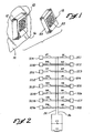
- Fig. 1 depicts a typical proximity RFID reader unit 10 contained in a reader housing 12 which is mounted on a wall surface 14.
- the reader 10 may be an RK600 sold by SecuraKey equipped with an exteriorly mounted keypad 16 which provides an interface for accessing the reader's microprocessor control system. In most installations such access requires entry of an authorized passcode before the keyboard is enabled for reprogramming the reader unit.
- the keypad may also be used for entering a personal identification number (PIN) as an alternative to presentation of a key tag.
- PIN personal identification number
- a passive remote programmer 18 is shown having a housing 20 on which is mounted a keypad 22.
- the housing 20 may be a small enclosure sized for convenient hand held operation.
- the remote programmer's keypad may be a duplicate of the reader keypad 16, or may be configured differently.
- Switches S1 through S16 are normally open switches corresponding to sixteen keys arranged in a four-by-four matrix on the keypad 22.
- Integrated circuits IC1 through IC16 are sixteen similar transponder tag ICs each programmed to transmit a unique identification code when activated by the inductive sensing field of a proximity reader.
- the transponder IC's may be TEMIC e5550 devices which operate with the RK600 reader.
- Antenna coil L1 and capacitor C1 form an antenna tank circuit which is resonant at the transmitter frequency of the proximity reader.
- L1 may be a 1.62 mH coil and C1 may have a value of 1000 pF.
- Each tag IC has two active terminals, one of which is connected directly to one side of the antenna tank circuit by means of bus line 24. The other active terminal of each tag IC is connected through a corresponding normally open switch S1-S16 to the other side of the antenna tank circuit by means of bus line 26. In a normal condition of the programmer all switches S1-S16 are open and none of IC1-IC16 are connected to the antenna circuit. Consequently, if the remote programmer unit 18 is placed in this condition within the sensing field of the reader unit 10, the programmer unit will not respond to the reader's sensing field.
- the corresponding one of IC1-IC16 will have both of its active terminals operatively connected across the antenna tank circuit.
- the operative IC will be powered up by energy inductively coupled from the reader to the antenna coil L1, and will transmit its unique tag code to the reader.
- the transponder IC may be in the form of surface mount dies and the entire circuit of Figure 2 can be easily implemented on a single circuit board which can also carry the keypad and antenna coil. The resulting package is lightweight and rugged.
- the passive programmer disclosed herein improves over prior passive programmers not only in terms of greater simplicity and economy, but also in extended operating range from the proximity reader because the transponder tag ICs have lower power requirements than more complex passive programmers.
- the program executed by the reader's microprocessor is written to recognize the unique tag codes of the programmer's transponder tag ICs IC1-IC16 as dedicated to a function other than ordinary access key tag data.
- the reader's program should recognize the reading of the dedicated tag codes as representing the actuation of a key rather than the presentation of a conventional key tag to the proximity reader. This recognition may be exploited by the programmer of the reader for any desired purpose.
- keys corresponding to the digits 0 through 9 may each be represented by a particular and unique tag code, so that numerical data may be entered into the reader by pressing a sequence of keys.
- Logic function keys such as ADD or DELETE may be similarly represented by corresponding unique tag codes.
- Still other control functions such as an ENTER key on the keyboard, may also be assigned corresponding tag codes.
- the remote programmer may be used to add to or delete authorized key tags in the reader's data base, as by pressing a sequence of digits followed by pressing an ENTER key, or to enter PIN codes into the reader as an alternative to using the keypad 16 on the reader unit 10.
- the remote programmer can replace altogether the keypad on the reader with no sacrifice in programmability of the reader, resulting in a more secure installation since the keypad is no longer accessible on the reader.
- elimination of the keypad makes it possible to better seal the reader enclosure or housing for better weather proofing and resistance to environmental contaminants.
- the manner of programming the reader's microprocessor to accomplish such recognition will be apparent to those having ordinary knowledge of such systems and need not be described in greater detail here, particularly in view of the many ways in which proximity reader systems can be programmed both for conventional purposes and for purposes of implementing this invention.
- the programming which controls operation of the reader's microprocessor may be installed as firmware in non-volatile memory provided on the processor chip. Of course, other program storage devices may be provided for this purpose.
- the reader control program should contain information to enable the reader to identify the unique ID code transmitted by the transponder tag ICs in the remote programmer so that these are distinguishable from other transponder tags not enabled by actuation of a key or switch, such as conventional key tags.
- This information is distinct from the data base which the microprocessor accesses in order to identify conventional key tags authorized for access.
- Recognition of key enabled transponder ICs permits programming of the reader to take special action in response to such tag IC readings, different from action taken in response to conventional tags which are enabled simply by sufficient proximity to the reader.
- keypad keys which can be encoded and wirelessly linked to a reader in this fashion is virtually unlimited. As a practical matter, however, it may be found that this approach to passive remote programming is best suited to smaller keypads, while programmer units requiring large and complex keyboards are better implemented with microprocessor driven circuits or the like.
- this invention is not restricted to any particular manufacturer's proximity systems, and is generally useful with any induction type proximity readers, provided that the tag ICs used in the remote programmer unit can be read by the target proximity reader.
Landscapes
- Engineering & Computer Science (AREA)
- Physics & Mathematics (AREA)
- General Physics & Mathematics (AREA)
- Theoretical Computer Science (AREA)
- Artificial Intelligence (AREA)
- Computer Vision & Pattern Recognition (AREA)
- Computer Networks & Wireless Communication (AREA)
- Health & Medical Sciences (AREA)
- Toxicology (AREA)
- General Health & Medical Sciences (AREA)
- Electromagnetism (AREA)
- Computer Hardware Design (AREA)
- Microelectronics & Electronic Packaging (AREA)
- Lock And Its Accessories (AREA)
- Near-Field Transmission Systems (AREA)
- Selective Calling Equipment (AREA)
- Input From Keyboards Or The Like (AREA)
- Burglar Alarm Systems (AREA)
- Electrotherapy Devices (AREA)
- Details Of Television Systems (AREA)
Claims (10)
- Passives Fernprogrammiersystem für einen RFID-Leser (10) vom Induktionstyp mit RF-Messmitteln, die in Wirkbeziehung mit einem Mikroprozessor verbunden sind, um die Tag-Identifikationsdaten von RFID-Transponder-Tags, die durch ein Messfeld des Lesers aktiviert werden, zu lesen, und um diese Identifikationsdaten gegen gespeicherte Identifikationsdaten zu prüfen, um dadurch das Vorhandensein zulässiger Tags zu erkennen, wobei dieses Programmiersystem umfasst:eine Handprogrammiereinheit (18), in der eine Antenne (L1, C1, eine Vielzahl von dedizierten RFID-Transponder-Tags (IC1-IC16), die alle einen einmaligen Tag-Code aufweisen, und ein Tastenfeld (22) mit mehreren Tasten untergebracht sind, die alle auf selektive Weise betätigbar sind, um einen entsprechenden der dedizierten RFID-Transponder-Tags (IC1-IC16) mit der Antenne (L1, C1) zu verbinden, wodurch das gewählte Tag durch Induktion in diesem Messfeld eingeschaltet wird und der einmalige Tag-Code vom RFID-Leser (10) gelesen werden kann; undProgrammmittel, die mit dem Mikroprozessor zusammenwirkend betreibbar sind, um eine erste Aktion in Antwort auf die Erkennung von Tags auszuführen, die durch die bloße Nähe des Lesers (10) im Messfeld vorliegen, und eine zweite Aktion, die sich von der ersten Aktion unterscheidet, in Antwort auf die Erkennung des dedizierten RFID-Transponder-Tags, das durch Betätigen einer Taste des Tastenfelds (22) aktiviert wurde, derart auszuführen, dass die Antwort des RFID-Lesers (10) auf diese Tags, die durch bloße Nähe vorliegen, durch Betätigen der Tasten in diesem Tastenfeld (22) modifiziert werden kann.
- Passives Programmiergerät nach Anspruch 1, wobei die Programmmittel auch betreibbar sind, um die Erkennung jedes einmaligen Tag-Codes als eine neue Programmanweisung zur Ausführung durch den Mikroprozessor zu interpretieren.
- Passives Programmiergerät nach Anspruch 2, wobei diese neue Programmanweisung Daten zum Modifizieren einer Transponder-Tag-Datenbank umfasst, auf die der Mikroprozessor zugreifen kann, um sie unter der Steuerung der Programmmittel in Entscheidungsalgorithmen zu verwenden.
- Passives Programmiergerät nach Anspruch 1, wobei die Tasten normalerweise offene Schalter (S1-S16) sind.
- Verfahren zur drahtlosen Verbindung eines Tastenfelds mit einem RFID-Leser (10) vom Induktionstyp, umfassend die Schritte des:das Vorsehen eines Tastenfelds (22), das eine Vielzahl von manuell betätigbaren Schalttasten aufweist.das Verbinden jeder dieser Schalttasten mit einem entsprechenden RFID-Transponder-Tag (IC1-IC16) und einer Antenne (L1, C1) derart, dass das Betätigen jeder dieser Schalttasten einen entsprechenden Transponder-Tag in Wirkverbindung mit der Antenne setzt, um einen einmaligen Identifikationscode jedes Tags durch Induktion zum RFID-Leser (10) zu übertragen; undProgrammmittel, die vom Mikroprozessormittel im RFID-Leser (10) ausführbar sind, um den einmaligen Identifikationscode jedes Tags, der mit dem Tastenfeld (22) verbunden ist, als repräsentativ für die Betätigung einer bestimmten Taste in diesem Tastenfeld (22) zu erkennen und nicht als Anzeige des Vorliegens eines Tasten-Tags durch bloße Nähe zum Leser (10).
- Verfahren nach Anspruch 5, außerdem umfassend den Schritt der Ausführung der Programmmittel durch den Leser (10), der mit der Betätigung einer bestimmten Taste verknüpft ist.
- Verfahren nach Anspruch 6, wobei der Schritt des Ausführens der Programmmittel die Antwort des Lesers auf Tasten-Tags modifiziert, die durch bloße Nähe zum Leser (10) vorliegen.
- RFID-System, umfassend:einen RFID-Leser (10) mit RF-Messmitteln, die in Wirkbeziehung mit einem Mikroprozessor zum Lesen von RFID-Tag verbunden sind, die durch bloße Nähe zum RFID-Leser in einem Messfeld dieses Lesers aktiviert werden; undeine Programmiereinheit (18), umfassend eine Antenne (L1, C1), eine Vielzahl von dedizierten RFID-Transponder-Tags (IC1-IC16), die alle einen einmaligen Tag-Code aufweisen, und ein Tastenfeld (22) mit mehreren Tasten, die alle auf selektive Weise betätigbar sind, um einen entsprechenden der dedizierten RFID-Transponder-Tags (IC1-IC16) mit der Antenne (L1, C1) zu verbinden, wodurch das gewählte Tag durch Induktion in diesem Messfeld eingeschaltet wird und der einmalige Tag-Code vom RFID-Leser (10) gelesen werden kann;wobei der Mikroprozessor programmiert ist, um auf das Lesen eines dieser einmaligen Tag-Codes auf eine Weise zu antworten, die sich von seiner Antwort auf das Lesen von RFID-Tags, die durch bloße Nähe zum Leser aktiviert werden, unterscheidet.
- RFID-Lesersystem nach Anspruch 8, wobei der Mikroprozessor programmiert ist, um eine Zugriffskontrollfunktion in Antwort auf das Lesen von RFID-Tags auszuführen, die durch bloße Nähe zum Leser (10) aktiviert werden, und um die Programmierung des Lesers (10) in Antwort auf das Lesen eines einmaligen Tag-Codes zu modifizieren.
- RFID-Lesersystem nach Anspruch 8, wobei die Programmiereinheit (18) ein tragbares Gehäuse (20) umfasst, das die Antenne (L1, C1) enthält, und die dedizierten RFID-Transponder-Tags (IC1-IC16) und das Tastenfeld (22) auf dem Gehäuse (20) montiert sind.
Applications Claiming Priority (3)
| Application Number | Priority Date | Filing Date | Title |
|---|---|---|---|
| US212583 | 1998-12-14 | ||
| US09/212,583 US6285295B1 (en) | 1998-12-14 | 1998-12-14 | Passive remote programmer for induction type RFID readers |
| PCT/US1999/029362 WO2000036849A1 (en) | 1998-12-14 | 1999-12-10 | Passive remote programmer for induction type rfid readers |
Publications (3)
| Publication Number | Publication Date |
|---|---|
| EP1101364A1 EP1101364A1 (de) | 2001-05-23 |
| EP1101364A4 EP1101364A4 (de) | 2004-11-24 |
| EP1101364B1 true EP1101364B1 (de) | 2009-10-07 |
Family
ID=22791638
Family Applications (1)
| Application Number | Title | Priority Date | Filing Date |
|---|---|---|---|
| EP99961962A Expired - Lifetime EP1101364B1 (de) | 1998-12-14 | 1999-12-10 | Passive fernprogrammiereinrichtung für nach dem prinzip der induktion arbeitenden rf indentifizierungsleser |
Country Status (8)
| Country | Link |
|---|---|
| US (1) | US6285295B1 (de) |
| EP (1) | EP1101364B1 (de) |
| AT (1) | ATE445295T1 (de) |
| AU (1) | AU758377B2 (de) |
| CA (1) | CA2348642C (de) |
| DE (1) | DE69941507D1 (de) |
| ES (1) | ES2356333T3 (de) |
| WO (1) | WO2000036849A1 (de) |
Families Citing this family (89)
| Publication number | Priority date | Publication date | Assignee | Title |
|---|---|---|---|---|
| US7880594B2 (en) * | 2000-09-08 | 2011-02-01 | Automotive Technologies International, Inc. | Switch assemblies and method for controlling vehicular components |
| US7012504B2 (en) * | 2002-04-01 | 2006-03-14 | Micron Technology, Inc. | Wireless identification device, RFID device with push-on/push off switch, and method of manufacturing wireless identification device |
| US6768415B1 (en) * | 1997-10-03 | 2004-07-27 | Micron Technology, Inc. | Wireless identification device, RFID device with push-on/push-off switch, method of manufacturing wireless identification device |
| US6828902B2 (en) | 1998-12-14 | 2004-12-07 | Soundcraft, Inc. | Wireless data input to RFID reader |
| US6650254B1 (en) | 2000-03-13 | 2003-11-18 | Ergodex | Computer input device with individually positionable and programmable switches |
| US7315949B1 (en) * | 2000-06-24 | 2008-01-01 | Palm, Inc. | Method and system for providing a personal identification security feature to a portable computing device |
| DE10039868C2 (de) * | 2000-08-16 | 2003-03-06 | Brose Fahrzeugteile | Verstelleinrichtung und Verfahren zur Betätigung einer Sitzverstellung, eines Fensterhebers oder eines Schiebedachs eines Kraftfahrzeugs |
| US7525453B2 (en) * | 2000-10-17 | 2009-04-28 | Henty David L | Computer system with enhanced range passive wireless keyboard |
| GB0028093D0 (en) * | 2000-11-17 | 2001-01-03 | Ratcliffe Anthony B | Electrical power control system |
| US8315563B2 (en) * | 2000-12-22 | 2012-11-20 | Google Inc. | Wireless reader tags (WRTs) with sensor components in asset monitoring and tracking systems |
| US20100330930A1 (en) * | 2000-12-22 | 2010-12-30 | Twitchell Robert W | Lprf device wake up using wireless tag |
| US20080303897A1 (en) * | 2000-12-22 | 2008-12-11 | Terahop Networks, Inc. | Visually capturing and monitoring contents and events of cargo container |
| US7522568B2 (en) * | 2000-12-22 | 2009-04-21 | Terahop Networks, Inc. | Propagating ad hoc wireless networks based on common designation and routine |
| US8280345B2 (en) * | 2000-12-22 | 2012-10-02 | Google Inc. | LPRF device wake up using wireless tag |
| US7563991B2 (en) * | 2005-06-08 | 2009-07-21 | Terahop Networks, Inc. | All weather housing assembly for electronic components |
| US7554442B2 (en) * | 2005-06-17 | 2009-06-30 | Terahop Networks, Inc. | Event-driven mobile hazmat monitoring |
| DE20110585U1 (de) * | 2001-06-11 | 2001-11-15 | Cubit Electronics GmbH, 99099 Erfurt | Kontaktloser Transponder |
| US7993197B2 (en) | 2001-08-10 | 2011-08-09 | Igt | Flexible loyalty points programs |
| US8430749B2 (en) | 2001-08-10 | 2013-04-30 | Igt | Dynamic casino tracking and optimization |
| US7946917B2 (en) * | 2001-08-10 | 2011-05-24 | Igt | Flexible loyalty points programs |
| US20030103472A1 (en) * | 2001-09-30 | 2003-06-05 | Ronald Taylor | RF wireless access control for locking system |
| US20030098780A1 (en) * | 2001-09-30 | 2003-05-29 | Ronald Taylor | General access control features for a RF access control system |
| US20030096607A1 (en) * | 2001-09-30 | 2003-05-22 | Ronald Taylor | Maintenance/trouble signals for a RF wireless locking system |
| US20030074936A1 (en) * | 2001-09-30 | 2003-04-24 | Fred Conforti | Door wireless access control system including reader, lock, and wireless access control electronics including wireless transceiver |
| US7248836B2 (en) * | 2001-09-30 | 2007-07-24 | Schlage Lock Company | RF channel linking method and system |
| US7113073B2 (en) * | 2001-09-30 | 2006-09-26 | Harrow Products, Llc | System management interface for radio frequency access control |
| US7346331B2 (en) * | 2001-09-30 | 2008-03-18 | Harrow Products, Llc | Power management for locking system |
| US7289764B2 (en) | 2001-09-30 | 2007-10-30 | Harrow Products, Llc | Cardholder interface for an access control system |
| US20030212597A1 (en) * | 2002-05-10 | 2003-11-13 | Igt | Multi-level point accumulation for a player tracking system and method |
| US8979646B2 (en) | 2002-06-12 | 2015-03-17 | Igt | Casino patron tracking and information use |
| JP2004021734A (ja) * | 2002-06-18 | 2004-01-22 | Nokia Corp | キーパッドおよびキーパッドシステム |
| US6903662B2 (en) | 2002-09-19 | 2005-06-07 | Ergodex | Computer input device with individually positionable and programmable input members |
| JP2004201481A (ja) * | 2002-10-23 | 2004-07-15 | Fanuc Ltd | Id情報の読出し装置、及びid情報読み出し装置を備える機器 |
| US20060059963A1 (en) * | 2004-01-20 | 2006-03-23 | Harrow Products Llc | Wireless access control system including wireless exit kit (''WEXK'') with panic bar |
| US7747286B2 (en) * | 2004-01-20 | 2010-06-29 | Harrow Products Llc | Wireless access control system with energy-saving piezo-electric locking |
| US7315908B2 (en) * | 2004-04-09 | 2008-01-01 | Gateway Inc. | Computer and RFID-based input devices |
| US20060065740A1 (en) * | 2004-09-24 | 2006-03-30 | Lyons Nicholas P | Low cost user input module |
| US7339476B2 (en) * | 2004-11-10 | 2008-03-04 | Rockwell Automation Technologies, Inc. | Systems and methods that integrate radio frequency identification (RFID) technology with industrial controllers |
| US7551081B2 (en) * | 2004-11-10 | 2009-06-23 | Rockwell Automation Technologies, Inc. | Systems and methods that integrate radio frequency identification (RFID) technology with agent-based control systems |
| US20070067325A1 (en) * | 2005-02-14 | 2007-03-22 | Xsapio, Ltd. | Methods and apparatus to load and run software programs in data collection devices |
| US7327216B2 (en) * | 2005-03-28 | 2008-02-05 | Lear Corporation | Secret key programming technique for transponders using encryption |
| US7636044B1 (en) | 2005-05-13 | 2009-12-22 | Rockwell Automation Technologies, Inc. | RFID tag programming, printing application, and supply chain/global registration architecture |
| US7616117B2 (en) | 2005-07-19 | 2009-11-10 | Rockwell Automation Technologies, Inc. | Reconciliation mechanism using RFID and sensors |
| US7388491B2 (en) * | 2005-07-20 | 2008-06-17 | Rockwell Automation Technologies, Inc. | Mobile RFID reader with integrated location awareness for material tracking and management |
| US7764191B2 (en) | 2005-07-26 | 2010-07-27 | Rockwell Automation Technologies, Inc. | RFID tag data affecting automation controller with internal database |
| US8260948B2 (en) | 2005-08-10 | 2012-09-04 | Rockwell Automation Technologies, Inc. | Enhanced controller utilizing RFID technology |
| US7510110B2 (en) | 2005-09-08 | 2009-03-31 | Rockwell Automation Technologies, Inc. | RFID architecture in an industrial controller environment |
| US20070057792A1 (en) * | 2005-09-12 | 2007-03-15 | Alden Ray M | Contact arrays and processes for wireless batteryless user input |
| US7570166B2 (en) * | 2005-09-12 | 2009-08-04 | Alden Ray M | RFID transponder arrays for sensing input and controlling processes |
| US9000883B2 (en) * | 2005-09-20 | 2015-04-07 | GM Global Technology Operations LLC | Control apparatus and method utilizing identifying keys |
| US7931197B2 (en) | 2005-09-20 | 2011-04-26 | Rockwell Automation Technologies, Inc. | RFID-based product manufacturing and lifecycle management |
| US7446662B1 (en) | 2005-09-26 | 2008-11-04 | Rockwell Automation Technologies, Inc. | Intelligent RFID tag for magnetic field mapping |
| US8025227B2 (en) | 2005-09-30 | 2011-09-27 | Rockwell Automation Technologies, Inc. | Access to distributed databases via pointer stored in RFID tag |
| US7760100B2 (en) * | 2005-10-18 | 2010-07-20 | August Clifford J | Systems and methods for storing and transferring personal data |
| US20070085663A1 (en) * | 2005-10-18 | 2007-04-19 | August Clifford J | Data exchange systems and methods employing RF data transmission |
| JP5105198B2 (ja) | 2006-02-03 | 2012-12-19 | ワン2タッチ エーエス | 外付けキーボード |
| US20080174403A1 (en) * | 2006-02-09 | 2008-07-24 | Michael Wolpert | Multiple wireless access points for wireless locksets |
| TW200731139A (en) * | 2006-02-14 | 2007-08-16 | Benq Corp | Wireless cursor pointing device without device |
| US20180203524A1 (en) * | 2006-02-27 | 2018-07-19 | Ezero Technologies Llc | Wireless backscatter communication system and method |
| CN1968129B (zh) * | 2006-08-31 | 2012-08-08 | 华为技术有限公司 | 一种设备配置的方法、系统及待配置设备 |
| US20080094181A1 (en) * | 2006-10-24 | 2008-04-24 | Tagsys Sas | Passive remote control |
| CN100559412C (zh) * | 2006-12-22 | 2009-11-11 | 宏碁股份有限公司 | 按键模组化的遥控器 |
| WO2008106784A1 (en) * | 2007-03-05 | 2008-09-12 | Argenia Systems Inc. | Batteryless and contactless keyboard control panel and distributed control system |
| WO2008117244A1 (en) * | 2007-03-27 | 2008-10-02 | Koninklijke Philips Electronics N.V. | Control circuit, system for operating a device and device for programming such a control circuit |
| US8692655B2 (en) * | 2007-05-07 | 2014-04-08 | Bloomberg Finance L.P. | Dynamically programmable RFID transponder |
| US20090091469A1 (en) * | 2007-10-09 | 2009-04-09 | Martine Kempf | Control device to actuate electrical functions of an automobile by a handicapped driver |
| US8279039B2 (en) * | 2007-10-12 | 2012-10-02 | Sony Mobile Communications Ab | Using touches to transfer information to a device |
| US20090128300A1 (en) * | 2007-11-19 | 2009-05-21 | Keystone Technology Solutions, Llc | Wireless device with an rfid interrogator |
| DE102008056930A1 (de) | 2007-11-19 | 2009-12-31 | Brühn, Xenia | Drahtlose Funkidentifikation |
| US8237550B2 (en) * | 2008-03-11 | 2012-08-07 | Microsoft Corporation | Action using switched device that transmits data |
| GB2461334B (en) * | 2008-07-01 | 2012-06-06 | Univ Wales Inst | Prototyping techniques |
| US20100182160A1 (en) * | 2009-01-21 | 2010-07-22 | Ming-Wei Lu | Remote control with passive RFID tag and Zigbee arrangement |
| US8705523B2 (en) * | 2009-02-05 | 2014-04-22 | Google Inc. | Conjoined class-based networking |
| US8162737B2 (en) * | 2009-05-27 | 2012-04-24 | Igt | Contactless player card with improved security |
| US20100277320A1 (en) * | 2009-06-30 | 2010-11-04 | Gold Steven K | RFID Keypad Assemblies |
| US20110063108A1 (en) * | 2009-09-16 | 2011-03-17 | Seiko Epson Corporation | Store Surveillance System, Alarm Device, Control Method for a Store Surveillance System, and a Program |
| FR2954548B1 (fr) | 2009-12-18 | 2013-10-04 | Schneider Electric Ind Sas | Systeme de dialogue homme-machine |
| US8798688B2 (en) | 2011-01-20 | 2014-08-05 | Clifford August | Systems and methods for transmitting data using near field communications |
| DE102011016089A1 (de) | 2011-04-05 | 2012-10-11 | Sciknowtec Gmbh | Verfahren zur Näherungs- und Trennungsdetektion mittels unvollständiger Transpondermarkierung und Markierung dazu |
| CN102221895A (zh) * | 2011-06-24 | 2011-10-19 | 鸿富锦精密工业(深圳)有限公司 | 无线键盘及具有无线键盘的计算机 |
| US8917161B2 (en) | 2011-10-21 | 2014-12-23 | Clifford J. August | Systems and methods for transmitting data using near field communications |
| US9112790B2 (en) | 2013-06-25 | 2015-08-18 | Google Inc. | Fabric network |
| JP6413459B2 (ja) | 2014-08-08 | 2018-10-31 | 株式会社デンソーウェーブ | カードリーダ |
| JP6318964B2 (ja) * | 2014-08-08 | 2018-05-09 | 株式会社デンソーウェーブ | カードリーダ |
| CN104318295A (zh) * | 2014-10-17 | 2015-01-28 | 上海真灼电子技术有限公司 | 具有拨号通话功能的双频复用天线rfid标签 |
| CN104299027A (zh) * | 2014-10-17 | 2015-01-21 | 上海真灼电子技术有限公司 | 可实现电话机通话的双频复用天线rfid标签 |
| GB201506954D0 (en) | 2015-04-23 | 2015-06-10 | Royal College Of Art | Communications device system and method |
| EP3304428A4 (de) * | 2015-05-29 | 2019-04-03 | Hive Technology | Verfahren und vorrichtung zur auswahl einer drahtlosen leseraktion durch von einer drahtlosen identifikationsvorrichtung empfangene ausgabedaten |
| DE112018000705T5 (de) | 2017-03-06 | 2019-11-14 | Cummins Filtration Ip, Inc. | Erkennung von echten filtern mit einem filterüberwachungssystem |
Family Cites Families (10)
| Publication number | Priority date | Publication date | Assignee | Title |
|---|---|---|---|---|
| US3733861A (en) * | 1972-01-19 | 1973-05-22 | Recognition Devices | Electronic recognition door lock |
| US4067011A (en) * | 1976-10-22 | 1978-01-03 | Motorola, Inc. | Digital transponder universal pulse assembly |
| US6822553B1 (en) * | 1985-10-16 | 2004-11-23 | Ge Interlogix, Inc. | Secure entry system with radio reprogramming |
| GB2239571B (en) * | 1989-12-29 | 1994-08-03 | Schlumberger Ind Ltd | Transponder |
| US5537103A (en) | 1993-05-20 | 1996-07-16 | Harrow Products, Inc. | Programmer for contact readable electronic control system and programming method therefor |
| US5815084A (en) * | 1993-05-20 | 1998-09-29 | Harrow Products, Inc. | Programmer for contact readable electronic control system and programming method therefor |
| US5461385A (en) * | 1994-04-29 | 1995-10-24 | Hughes Identification Devices, Inc. | RF/ID transponder system employing multiple transponders and a sensor switch |
| DE19607017C2 (de) * | 1996-02-24 | 2000-06-29 | Daimler Chrysler Ag | Fernbedienungseinrichtung und Betriebsverfahren hierfür, insbesondere zur Ansteuerung von kraftfahrzeugbezogenen Einrichtungen |
| US5748106A (en) * | 1996-03-25 | 1998-05-05 | Delco Electronics Corp. | Method and apparatus for controlling transponder signaling |
| DE29715426U1 (de) * | 1997-08-28 | 1997-12-11 | DATASEC Electronic GmbH, 15344 Strausberg | Berührungslos betätigbare Schalteinheit |
-
1998
- 1998-12-14 US US09/212,583 patent/US6285295B1/en not_active Expired - Lifetime
-
1999
- 1999-12-10 AT AT99961962T patent/ATE445295T1/de not_active IP Right Cessation
- 1999-12-10 ES ES99961962T patent/ES2356333T3/es not_active Expired - Lifetime
- 1999-12-10 WO PCT/US1999/029362 patent/WO2000036849A1/en not_active Ceased
- 1999-12-10 CA CA002348642A patent/CA2348642C/en not_active Expired - Lifetime
- 1999-12-10 DE DE69941507T patent/DE69941507D1/de not_active Expired - Lifetime
- 1999-12-10 EP EP99961962A patent/EP1101364B1/de not_active Expired - Lifetime
- 1999-12-10 AU AU18436/00A patent/AU758377B2/en not_active Ceased
Also Published As
| Publication number | Publication date |
|---|---|
| WO2000036849A1 (en) | 2000-06-22 |
| EP1101364A4 (de) | 2004-11-24 |
| CA2348642C (en) | 2003-08-19 |
| EP1101364A1 (de) | 2001-05-23 |
| CA2348642A1 (en) | 2000-06-22 |
| ES2356333T3 (es) | 2011-04-07 |
| AU1843600A (en) | 2000-07-03 |
| DE69941507D1 (de) | 2009-11-19 |
| US6285295B1 (en) | 2001-09-04 |
| HK1037834A1 (en) | 2002-02-15 |
| ATE445295T1 (de) | 2009-10-15 |
| AU758377B2 (en) | 2003-03-20 |
Similar Documents
| Publication | Publication Date | Title |
|---|---|---|
| EP1101364B1 (de) | Passive fernprogrammiereinrichtung für nach dem prinzip der induktion arbeitenden rf indentifizierungsleser | |
| EP1430729B1 (de) | Drahtlose dateneingabe für einen rfid-leser | |
| AU2002330971A1 (en) | Wireless data input to RFID reader | |
| US6133833A (en) | Wireless add-on keyboard system and method | |
| CA2446295A1 (en) | Smart card access control system | |
| AU2008248013B2 (en) | Dynamically programmable RFID transponder | |
| US8508334B2 (en) | Inductive coupling exchange in a portable intelligent object with central and peripheral circuits | |
| US20080084271A1 (en) | Continuous variable wireless data input to RFID reader | |
| JP2007512611A (ja) | タグ及びスマートカードのための妨害器 | |
| KR20120048003A (ko) | 각종 판독 범위를 갖는 rfid 태그들을 구비한 rfid 포털 시스템 | |
| KR101308802B1 (ko) | 사람이 액세스할 수 있는 영역, 특히, 도어에 의해폐쇄되는 영역에 대한 액세스를 제어하는 방법 | |
| WO2003061146A1 (en) | A communications unit | |
| KR101003827B1 (ko) | 복수의 rfid칩을 갖는 비 접촉식 인식 카드 | |
| KR101276878B1 (ko) | 알에프아이디 시스템의 동작 제어 장치 및 방법 | |
| HK1037834B (en) | Passive remote programmer for induction type rfid readers | |
| KR20090013493A (ko) | 알에프아이디 키보드 시스템 | |
| WO2007064178A1 (en) | Apparatus for operating control of rfid | |
| KR100302086B1 (ko) | 비접촉식카드인식단말기의인식변수자동설정방법 | |
| KR200176178Y1 (ko) | 무선 통신용 태그를 내장한 스마트 카드 | |
| JPH09311185A (ja) | 情報監査システムで使用する装置 |
Legal Events
| Date | Code | Title | Description |
|---|---|---|---|
| PUAI | Public reference made under article 153(3) epc to a published international application that has entered the european phase |
Free format text: ORIGINAL CODE: 0009012 |
|
| 17P | Request for examination filed |
Effective date: 20010306 |
|
| AK | Designated contracting states |
Kind code of ref document: A1 Designated state(s): AT BE CH CY DE DK ES FI FR GB GR IE IT LI LU MC NL PT SE |
|
| AX | Request for extension of the european patent |
Free format text: AL;LT;LV;MK;RO;SI |
|
| A4 | Supplementary search report drawn up and despatched |
Effective date: 20041012 |
|
| RIC1 | Information provided on ipc code assigned before grant |
Ipc: 7G 07C 9/00 B Ipc: 7G 06K 19/077 B Ipc: 7H 04M 3/00 B Ipc: 7G 06K 19/07 B Ipc: 7H 04Q 1/00 A |
|
| RAP1 | Party data changed (applicant data changed or rights of an application transferred) |
Owner name: CASDEN, MARTIN S. Owner name: SOUNDCRAFT, INC. |
|
| 17Q | First examination report despatched |
Effective date: 20081212 |
|
| GRAP | Despatch of communication of intention to grant a patent |
Free format text: ORIGINAL CODE: EPIDOSNIGR1 |
|
| GRAS | Grant fee paid |
Free format text: ORIGINAL CODE: EPIDOSNIGR3 |
|
| GRAA | (expected) grant |
Free format text: ORIGINAL CODE: 0009210 |
|
| AK | Designated contracting states |
Kind code of ref document: B1 Designated state(s): AT BE CH CY DE DK ES FI FR GB GR IE IT LI LU MC NL PT SE |
|
| REG | Reference to a national code |
Ref country code: GB Ref legal event code: FG4D |
|
| REG | Reference to a national code |
Ref country code: CH Ref legal event code: EP |
|
| REG | Reference to a national code |
Ref country code: IE Ref legal event code: FG4D |
|
| REF | Corresponds to: |
Ref document number: 69941507 Country of ref document: DE Date of ref document: 20091119 Kind code of ref document: P |
|
| REG | Reference to a national code |
Ref country code: SE Ref legal event code: TRGR |
|
| REG | Reference to a national code |
Ref country code: HK Ref legal event code: GR Ref document number: 1037834 Country of ref document: HK |
|
| PG25 | Lapsed in a contracting state [announced via postgrant information from national office to epo] |
Ref country code: PT Free format text: LAPSE BECAUSE OF FAILURE TO SUBMIT A TRANSLATION OF THE DESCRIPTION OR TO PAY THE FEE WITHIN THE PRESCRIBED TIME-LIMIT Effective date: 20100208 Ref country code: FI Free format text: LAPSE BECAUSE OF FAILURE TO SUBMIT A TRANSLATION OF THE DESCRIPTION OR TO PAY THE FEE WITHIN THE PRESCRIBED TIME-LIMIT Effective date: 20091007 |
|
| PG25 | Lapsed in a contracting state [announced via postgrant information from national office to epo] |
Ref country code: AT Free format text: LAPSE BECAUSE OF FAILURE TO SUBMIT A TRANSLATION OF THE DESCRIPTION OR TO PAY THE FEE WITHIN THE PRESCRIBED TIME-LIMIT Effective date: 20091007 |
|
| PG25 | Lapsed in a contracting state [announced via postgrant information from national office to epo] |
Ref country code: MC Free format text: LAPSE BECAUSE OF NON-PAYMENT OF DUE FEES Effective date: 20100701 Ref country code: DK Free format text: LAPSE BECAUSE OF FAILURE TO SUBMIT A TRANSLATION OF THE DESCRIPTION OR TO PAY THE FEE WITHIN THE PRESCRIBED TIME-LIMIT Effective date: 20091007 |
|
| REG | Reference to a national code |
Ref country code: CH Ref legal event code: PL |
|
| PLBE | No opposition filed within time limit |
Free format text: ORIGINAL CODE: 0009261 |
|
| STAA | Information on the status of an ep patent application or granted ep patent |
Free format text: STATUS: NO OPPOSITION FILED WITHIN TIME LIMIT |
|
| 26N | No opposition filed |
Effective date: 20100708 |
|
| PG25 | Lapsed in a contracting state [announced via postgrant information from national office to epo] |
Ref country code: LI Free format text: LAPSE BECAUSE OF NON-PAYMENT OF DUE FEES Effective date: 20091231 Ref country code: GR Free format text: LAPSE BECAUSE OF FAILURE TO SUBMIT A TRANSLATION OF THE DESCRIPTION OR TO PAY THE FEE WITHIN THE PRESCRIBED TIME-LIMIT Effective date: 20100108 Ref country code: CH Free format text: LAPSE BECAUSE OF NON-PAYMENT OF DUE FEES Effective date: 20091231 |
|
| REG | Reference to a national code |
Ref country code: ES Ref legal event code: FG2A Ref document number: 2356333 Country of ref document: ES Kind code of ref document: T3 Effective date: 20110407 |
|
| PG25 | Lapsed in a contracting state [announced via postgrant information from national office to epo] |
Ref country code: LU Free format text: LAPSE BECAUSE OF NON-PAYMENT OF DUE FEES Effective date: 20091210 |
|
| PG25 | Lapsed in a contracting state [announced via postgrant information from national office to epo] |
Ref country code: CY Free format text: LAPSE BECAUSE OF FAILURE TO SUBMIT A TRANSLATION OF THE DESCRIPTION OR TO PAY THE FEE WITHIN THE PRESCRIBED TIME-LIMIT Effective date: 20091007 |
|
| REG | Reference to a national code |
Ref country code: FR Ref legal event code: PLFP Year of fee payment: 17 |
|
| REG | Reference to a national code |
Ref country code: FR Ref legal event code: PLFP Year of fee payment: 18 |
|
| REG | Reference to a national code |
Ref country code: FR Ref legal event code: PLFP Year of fee payment: 19 |
|
| REG | Reference to a national code |
Ref country code: DE Ref legal event code: R082 Ref document number: 69941507 Country of ref document: DE Representative=s name: FLACH BAUER STAHL PATENTANWAELTE PARTNERSCHAFT, DE |
|
| PGFP | Annual fee paid to national office [announced via postgrant information from national office to epo] |
Ref country code: SE Payment date: 20181219 Year of fee payment: 20 Ref country code: IE Payment date: 20181210 Year of fee payment: 20 Ref country code: NL Payment date: 20181217 Year of fee payment: 20 |
|
| PGFP | Annual fee paid to national office [announced via postgrant information from national office to epo] |
Ref country code: BE Payment date: 20181217 Year of fee payment: 20 Ref country code: FR Payment date: 20181218 Year of fee payment: 20 Ref country code: GB Payment date: 20181219 Year of fee payment: 20 |
|
| PGFP | Annual fee paid to national office [announced via postgrant information from national office to epo] |
Ref country code: IT Payment date: 20181227 Year of fee payment: 20 Ref country code: DE Payment date: 20181228 Year of fee payment: 20 Ref country code: ES Payment date: 20190121 Year of fee payment: 20 |
|
| REG | Reference to a national code |
Ref country code: DE Ref legal event code: R071 Ref document number: 69941507 Country of ref document: DE |
|
| REG | Reference to a national code |
Ref country code: NL Ref legal event code: MK Effective date: 20191209 |
|
| REG | Reference to a national code |
Ref country code: GB Ref legal event code: PE20 Expiry date: 20191209 |
|
| REG | Reference to a national code |
Ref country code: BE Ref legal event code: MK Effective date: 20191210 |
|
| REG | Reference to a national code |
Ref country code: SE Ref legal event code: EUG |
|
| PG25 | Lapsed in a contracting state [announced via postgrant information from national office to epo] |
Ref country code: GB Free format text: LAPSE BECAUSE OF EXPIRATION OF PROTECTION Effective date: 20191209 |
|
| REG | Reference to a national code |
Ref country code: IE Ref legal event code: MK9A |
|
| PG25 | Lapsed in a contracting state [announced via postgrant information from national office to epo] |
Ref country code: IE Free format text: LAPSE BECAUSE OF EXPIRATION OF PROTECTION Effective date: 20191210 |
|
| REG | Reference to a national code |
Ref country code: ES Ref legal event code: FD2A Effective date: 20200903 |
|
| PG25 | Lapsed in a contracting state [announced via postgrant information from national office to epo] |
Ref country code: ES Free format text: LAPSE BECAUSE OF EXPIRATION OF PROTECTION Effective date: 20191211 |