EP1101580A2 - Dispositif ainsi que procédé de poinçonnage - Google Patents
Dispositif ainsi que procédé de poinçonnage Download PDFInfo
- Publication number
- EP1101580A2 EP1101580A2 EP00125144A EP00125144A EP1101580A2 EP 1101580 A2 EP1101580 A2 EP 1101580A2 EP 00125144 A EP00125144 A EP 00125144A EP 00125144 A EP00125144 A EP 00125144A EP 1101580 A2 EP1101580 A2 EP 1101580A2
- Authority
- EP
- European Patent Office
- Prior art keywords
- stamping
- processing surface
- section
- contact
- stamping section
- Prior art date
- Legal status (The legal status is an assumption and is not a legal conclusion. Google has not performed a legal analysis and makes no representation as to the accuracy of the status listed.)
- Withdrawn
Links
Images


Classifications
-
- B—PERFORMING OPERATIONS; TRANSPORTING
- B44—DECORATIVE ARTS
- B44B—MACHINES, APPARATUS OR TOOLS FOR ARTISTIC WORK, e.g. FOR SCULPTURING, GUILLOCHING, CARVING, BRANDING, INLAYING
- B44B5/00—Machines or apparatus for embossing decorations or marks, e.g. embossing coins
- B44B5/0061—Machines or apparatus for embossing decorations or marks, e.g. embossing coins characterised by the power drive
- B44B5/0066—Machines or apparatus for embossing decorations or marks, e.g. embossing coins characterised by the power drive producing a vibratory motion
Definitions
- the present invention relates to a stamping apparatus and a stamping method to stamp the production number or product name on the surface of metallic or synthetic resin material parts.
- An object of the present invention is to provide a stamping apparatus and a stamping method, by which the automatic control of the applying pressure onto a material to be stamped is realized by the low cost and easy structure.
- a stamping apparatus for example, a stamping apparatus 10 in Fig. 1 comprising: a stamping means (for example, a reciprocating mechanism section 1 in Fig. 1) for stamping on a processing surface of a material to be stamped by reciprocally moving a stamping section (for example, stylus lg in Fig. 1); a stamping section moving means (for example, a two-dimensional positioning mechanism section 3 in Fig. 1) for moving the stamping section in two-dimensional direction to the processing surface; and a applying pressure adjustment means (for example, a pressure control circuit 2 in Fig.
- the stamping apparatus is provided with a cam apparatus to reciprocally move the stamping section linearly when it is driven by the cam rotated by a driving means (for example, a motor 1a in Fig. 1).
- the stamping means stamps on the processing surface of the material to be stamped by reciprocally moving the stamping section; the stamping section moving means moves the stamping section in the two-dimensional direction to the processing surface; the applying pressure adjustment means adjusts the applying pressure so that a predetermined pressure is kept onto the processing surface; and the stamping means has the cam apparatus to reciprocally move the stamping section linearly when the cam in the stamping means is rotated by the driving means and the stamping section is driven by the cam.
- the pressing force applied on the material to be stamped is directly detected by using the reaction force from the stamping section, and this pressing force can be kept constant, therefore, the stamping apparatus by which the applying pressure can be adjusted, can be realized by the easy and small sized structure.
- the stamping apparatus further comprises a contact detection means (for example, a current amount detection resistance 28 in Fig. 4) for detecting the pressure of the stamping section onto the processing surface by the change of a current value flowing through the driving means; and the applying pressure adjustment means (for example, a pressure control circuit 2 in Fig. 1) adjusts the pressure onto the processing surface according to the detection result, when the contact of the stamping section with the processing surface is detected by the contact detection means.
- a contact detection means for example, a current amount detection resistance 28 in Fig. 4
- the applying pressure adjustment means for example, a pressure control circuit 2 in Fig. 1 adjusts the pressure onto the processing surface according to the detection result, when the contact of the stamping section with the processing surface is detected by the contact detection means.
- the contact detection means detects the contact of the stamping section with the processing surface by the change of a current value flowing through the driving means, and the applying pressure adjustment means adjusts the applying pressure onto the processing surface according to the detection result, when the contact of the stamping section with the processing surface is detected by the contact detection means.
- a stamping method comprising: a stamping step of reciprocally moving the stamping section linearly when it is driven by the cam rotated by a driving means; a stamping section moving step of moving the stamping section in the two-dimensional direction to the processing surface; a contact detection step of detecting the contact of the stamping section with the processing surface by the change of a current value flowing through the driving means; and a applying pressure adjustment step of causing the stamping section to maintain a predetermined applying pressure onto the processing surface, according to the detection result, when the contact of the stamping section with the processing surface is detected by the contact detection process.
- the stamping section driven when the cam is rotated by the driving means is reciprocally moved linearly; in the stamping section moving step, the stamping section is moved in the two-dimensional direction to the processing surface; in the contact detection step, the contact of the stamping section with the processing surface is detected by the change of the current value flowing through the driving means; and in the applying pressure adjustment step, when the contact of the stamping section with the processing surface is detected in the contact detection step, according to the result of the detection, the pressure is adjusted so that the stamping section maintains the predetermined applying pressure onto the processing surface.
- the material to be stamped can be stamped by the optimum speed and pressing force, corresponding to the difference in the weight of the stamping means or the contact position with the processing surface.
- the stamping apparatus according to the first or second aspect further comprises alarm output means (for example, an amplifier 29 in Fig. 4) for outputting the alarm, when it is detected that the stamping section does not contact with the processing surface by the contact detection means, at the time of reciprocating movement of the stamping section by the stamping means (for example, the reciprocating mechanism section 1 in Fig. 1).
- alarm output means for example, an amplifier 29 in Fig. 4 for outputting the alarm, when it is detected that the stamping section does not contact with the processing surface by the contact detection means, at the time of reciprocating movement of the stamping section by the stamping means (for example, the reciprocating mechanism section 1 in Fig. 1).
- the alarm output means outputs the alarm, when it is detected that the stamping section does not contact with the processing surface by the contact detection means, at the time of reciprocating movement of the stamping section by the stamping means.
- the stamping method according to the fifth aspect further comprises an alarm output step of outputting the alarm, when it is detected that the stamping section does not contact with the processing surface in the contact detection process, at the time of reciprocating movement of the stamping section in the stamping step.
- the alarm in the alarm output step, the alarm is outputted, when it is detected that the stamping section does not contact with the processing surface in the contact detection step, at the time of reciprocating movement of the stamping section in the stamping step.
- the stamping means is at the position at which the stamping can not conduct onto the material to be stamped, thereby, the time and electric power consumption can be saved.
- the stamping means (for example, the reciprocating mechanism section 1 in Fig. 1) has a cam with a cam curve by which the torque applied onto the driving means by the contact of the stamping section with the processing surface becomes constant without depending on the contact position with the processing surface.
- the stamping means has a cam with a cam curve by which the torque applied onto the driving means by the contact of the stamping section with the processing surface becomes constant without depending on the contact position with the processing surface.
- the stamping can be conducted in an uniform depth without depending on the contact position of the stamping section with the processing surface.
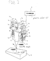
- Fig. 1 is a view showing the schematic structure of the stamping apparatus 10 in an embodiment of the present invention.
- the stamping apparatus 10 is approximately structured by a reciprocating mechanism section 1, pressure control circuit 2, two-dimensional positioning mechanism section 3, positioning control circuit 4 and stamping oscillation generating circuit 5. Further, the reciprocating mechanism section 1 is structured by a motor 1a, cam 1b, cam follower 1c, dog 1d, holding portion 1e, pen 1f, stylus 1g, up-movement end detector 1h, down-movement end detector 1i, shaft 1j, coil spring 1k, fixed plate 1l, stopper lm, bearing 1n, and the like.
- the motor 1a is attached on the fixed plate 1l, and when the motor 1a is driven and the cam 1b is rotated, the holding portion 1e is linearly moved through the cam follower 1c.
- the holding portion 1e is fixed on two shafts 1j, and is always pressed onto the cam 1b side by the coil spring 1k. Therefore, as the cam is rotated, even when the holding portion le is pressed and lowered toward the material to be stamped 6 side, or even when the holding portion le is separated from the material to be stamped 6 side, the holding portion 1e is moved following the cam 1b.
- the cam 1b has the shape in which the stylus 1g attached on the tip portion of the pen 1f can be pushed onto the material to be stamped 6 by a predetermined pressure by the predetermined torque from the motor 1a, without depending on its rotation position.
- the stylus lg is made of the material having the higher hardness than the material to be stamped 6, and by being oscillated in the up and down directions at high speed, point stamping is repeated onto the material to be stamped 6.
- a bearing 1n is housed in the fixed plate 1l, and the shaft 1j is guided by the bearing 1n, and linearly moved. Further, the cam follower 1c and the pen 1f are attached onto the holding portion 1e, and the up movement end detector 1h detects the dog 1d when the tip of the pen 1f attached on the bottom surface of the holding portion 1e is at the position of the up-movement end, and the down movement end detector 1i detects the dog 1d at the position of the down-movement end.
- the pressure control circuit 2 controls the speed of the reciprocating movement of the pen 1f by controlling the rotation speed of the motor 1a, as will be described later. Further, the pressure control circuit 2 detects the arrival to the material to be stamped 6 when the pen 1f comes into contact with the material to be stamped 6 during the reciprocating movement of the pen 1f, and after the contact of the pen 1f with the material to be stamped 6, the pressure control circuit 2 controls the pressure of the stylus 1g applied onto the material to be stamped 6 so that it becomes a predetermined value.
- the pressure control circuit 2 reversely rotates the motor 1a, and when the stylus 1g reaches the up-movement end, the pressure control circuit 2 stops the motor 1a, and outputs the alarm.
- the two-dimensional positioning mechanism section 3 positions the two-dimensional pattern such as characters or numerals in the perpendicular direction to the stamping axis, according to the positioning control signal outputted from the positioning control circuit 4.
- the reciprocating mechanism section 1 causes the pen 1f to contact with pressure with the material to be stamped 6 under the condition that the pen 1f is oscillated, and stamps the characters and numerals on the material to be stamped 6.
- the stamping oscillation generating circuit 5 causes the pen 1f to generate the oscillation.
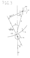
- a fulcrum 101 expresses the fulcrum of the cam 1b which is a rotation shaft of the motor 1a
- the contact point 102 expresses the contact point of the cam 1b with the cam follower 1c.
- [R] expresses the distance between the fulcrum 101 and the contact point 102
- [F] is the reaction force from the material to be stamped 6
- [T] expresses the torque which is generated in the fulcrum 101 by [F].
- [ ⁇ ] expresses an angle formed between the direction of the reaction force [F] and the direction of the reaction force of the cam follower 1c to the cam 1b
- [ ⁇ ] is an angle formed between the direction of [F] and the direction of [R]
- [ ⁇ ] expresses an angle formed between the direction of [F] and the direction of [F/cos ⁇ ] respectively.
- the cam 1b is formed with the curved shape to satisfy the above expression, and when the distance between the fulcrum 101 and the contact point 102 is appropriately changed as the rotation of the cam 1b, the pressure to be applied onto the material to be stamped 6 when a predetermined torque is applied from the motor la, can be kept constant.
- the change of the length of the coil spring 1k, [F] is changed, however, because the change of [F] is extremely small as compared to the pressure applied onto the material to be stamped 6, it can be neglected.
- a switch 25 inputs this signal into a comparator 24b so as to make this signal a comparing signal with the chopping wave outputted from a chopping wave generation circuit 26' in a PWM pulse generation circuit 26.
- the rotation speed of the motor 1a is controlled so that the output signal of the tachometer 1a' keeps a value which is previously set in the pulse ⁇ duty setting section 21a.
- the pressure control circuit 2 can control the speed of reciprocating movement of the pen 1f to the arbitrary speed.
- the current value is proportional to the torque, because the movement is restrained when the stylus 1g comes into contact with the material to be stamped 6, the torque of the motor la temporarily becomes excessive. Accordingly, by inputting the voltage of both ends of the current amount detection resistance 28 into the amplifier 29, the voltage is detected, and compared to the torque setting value of the torque setting section 21c previously stored by the comparator 24a, thereby, the arrival to the material to be stamped 6 is detected. Then, when the arrival to the material to be stamped 6 is not detected, the amplifier 29 stops the motor la and outputs the alarm. According to the above operations, the pressure control circuit 2 can detect the contact of the pen 1f with the material to be stamped 6 during the movement in the reciprocating motion.
- the subtracter 22b and the adder 23b compare the output value of the amplifier 29, which is a signal proportional to the [T], to the pulse ⁇ duty setting value stored in the pulse ⁇ duty setting section 21b, and the signal in which the difference is added to the pulse ⁇ duty setting value, is generated.
- the switch 25 inputs this signal into the comparator 24b so as to make this signal the comparing signal to the chopping wave outputted from the chopping wave generation circuit 26' in the PWM pulse generation circuit 26. Accordingly, the torque of the motor la is controlled so that the output signal of the amplifier 29 becomes the value which is previously set to the pulse ⁇ duty setting value of the pulse ⁇ duty setting section 21b. According to the above operations, the pressure control circuit 2 can control the pressure applied onto the material to be stamped 6 by the pen 1f, to the predetermined value.
- the pressure control circuit 2 controls the switch 25 according to the signal to detect the arrival to the material to be stamped 6, because the difference of the weight of the pen If does not influence on the intensity of the collision with the material to be stamped 6, various kinds of pens can be used. Further, the pressure control circuit 2 can conduct the speed control and applying pressure control of the pen 1f so that the pressing force of the stylus 1g becomes the optimum value, thereby, the stamping apparatus by which the homogeneous stamping is conducted onto the processing surface without depending on the material and the shape of the material to be stamped 6, can be structured inexpensively and easily.
- the stamping apparatus because the reaction force from the stamping section is used and the pressing force applied onto the material to be stamped is directly detected, and the pressing force can be kept constant, thereby, the stamping apparatus by which the applying pressure can be adjusted, can be realized in easy and small sized structure.
- the material to be stamped can be stamped by the optimum speed and applying predssure corresponding to the difference of the weight of the stamping means or the contact position with the processing surface.
- the time or power consumption can be saved.
- the stamping in addition to the effect of the invention according to the first aspect, by keeping the torque applied onto the driving means constant, the stamping can be conducted with the uniform depth without depending on the contact position of the stamping section with the processing surface.
Landscapes
- Control Of Presses (AREA)
- Shaping Metal By Deep-Drawing, Or The Like (AREA)
Applications Claiming Priority (2)
| Application Number | Priority Date | Filing Date | Title |
|---|---|---|---|
| JP32712699 | 1999-11-17 | ||
| JP32712699 | 1999-11-17 |
Publications (2)
| Publication Number | Publication Date |
|---|---|
| EP1101580A2 true EP1101580A2 (fr) | 2001-05-23 |
| EP1101580A3 EP1101580A3 (fr) | 2002-12-11 |
Family
ID=18195609
Family Applications (1)
| Application Number | Title | Priority Date | Filing Date |
|---|---|---|---|
| EP00125144A Withdrawn EP1101580A3 (fr) | 1999-11-17 | 2000-11-17 | Dispositif ainsi que procédé de poinçonnage |
Country Status (1)
| Country | Link |
|---|---|
| EP (1) | EP1101580A3 (fr) |
Cited By (11)
| Publication number | Priority date | Publication date | Assignee | Title |
|---|---|---|---|---|
| CN104624846A (zh) * | 2014-12-20 | 2015-05-20 | 珠海西比特精密模具有限公司 | 模具顶出机构检测系统 |
| CN105774355A (zh) * | 2016-05-10 | 2016-07-20 | 安徽坤昌家具有限公司 | 一种红木家具雕刻用凸轮 |
| CN105774358A (zh) * | 2016-05-10 | 2016-07-20 | 安徽坤昌家具有限公司 | 一种红木家具用雕刻刀 |
| CN105946419A (zh) * | 2016-05-10 | 2016-09-21 | 安徽坤昌家具有限公司 | 一种红木浮雕花瓣刻纹装置 |
| CN106182171A (zh) * | 2016-08-22 | 2016-12-07 | 王恒标 | 调节型冲孔设备 |
| CN107214364A (zh) * | 2017-07-11 | 2017-09-29 | 佛山市正略信息科技有限公司 | 一种铰链叶片连续高效打孔装置 |
| CN107499622A (zh) * | 2017-08-31 | 2017-12-22 | 安徽工程大学 | 一种高效自动印章打包机 |
| CN108393962A (zh) * | 2018-04-23 | 2018-08-14 | 大连华诺塑料科技有限公司 | 一种透气膜刺孔装置 |
| CN109531690A (zh) * | 2018-12-03 | 2019-03-29 | 安徽信盟装备股份有限公司 | 一种伺服电机驱动的门胆成型机扎孔设备 |
| CN109986645A (zh) * | 2019-04-11 | 2019-07-09 | 罗福斯办公用品(滁州)有限公司 | 一种5v电动打孔机 |
| WO2021046893A1 (fr) * | 2019-09-12 | 2021-03-18 | 苏州龙骐自动化科技有限公司 | Dispositif robotisé de perforation de feuille automatique |
Family Cites Families (4)
| Publication number | Priority date | Publication date | Assignee | Title |
|---|---|---|---|---|
| JPH0292417A (ja) * | 1988-09-29 | 1990-04-03 | Ando Electric Co Ltd | ペン軸の二重戻し機構つき彫刻器 |
| US5628673A (en) * | 1993-11-26 | 1997-05-13 | Seiko Seiki Kabushiki Kaisha | Dicing machine with non-contact setup function |
| JPH10181292A (ja) * | 1996-07-31 | 1998-07-07 | Ando Electric Co Ltd | 加工ヘッド用シフトバランス装置 |
| JP2000062395A (ja) * | 1998-08-24 | 2000-02-29 | Ando Electric Co Ltd | 彫刻ペン |
-
2000
- 2000-11-17 EP EP00125144A patent/EP1101580A3/fr not_active Withdrawn
Cited By (15)
| Publication number | Priority date | Publication date | Assignee | Title |
|---|---|---|---|---|
| CN104624846A (zh) * | 2014-12-20 | 2015-05-20 | 珠海西比特精密模具有限公司 | 模具顶出机构检测系统 |
| CN105774355A (zh) * | 2016-05-10 | 2016-07-20 | 安徽坤昌家具有限公司 | 一种红木家具雕刻用凸轮 |
| CN105774358A (zh) * | 2016-05-10 | 2016-07-20 | 安徽坤昌家具有限公司 | 一种红木家具用雕刻刀 |
| CN105946419A (zh) * | 2016-05-10 | 2016-09-21 | 安徽坤昌家具有限公司 | 一种红木浮雕花瓣刻纹装置 |
| CN106182171B (zh) * | 2016-08-22 | 2018-05-18 | 天津鑫润恒信新能源科技发展有限公司 | 调节型冲孔设备 |
| CN106182171A (zh) * | 2016-08-22 | 2016-12-07 | 王恒标 | 调节型冲孔设备 |
| CN107214364B (zh) * | 2017-07-11 | 2019-03-19 | 佛山市正略信息科技有限公司 | 一种铰链叶片连续高效打孔装置 |
| CN107214364A (zh) * | 2017-07-11 | 2017-09-29 | 佛山市正略信息科技有限公司 | 一种铰链叶片连续高效打孔装置 |
| CN107499622A (zh) * | 2017-08-31 | 2017-12-22 | 安徽工程大学 | 一种高效自动印章打包机 |
| CN107499622B (zh) * | 2017-08-31 | 2019-07-26 | 安徽工程大学 | 一种自动印章打包机 |
| CN108393962A (zh) * | 2018-04-23 | 2018-08-14 | 大连华诺塑料科技有限公司 | 一种透气膜刺孔装置 |
| CN108393962B (zh) * | 2018-04-23 | 2023-08-08 | 大连华诺塑胶科技有限公司 | 一种透气膜刺孔装置 |
| CN109531690A (zh) * | 2018-12-03 | 2019-03-29 | 安徽信盟装备股份有限公司 | 一种伺服电机驱动的门胆成型机扎孔设备 |
| CN109986645A (zh) * | 2019-04-11 | 2019-07-09 | 罗福斯办公用品(滁州)有限公司 | 一种5v电动打孔机 |
| WO2021046893A1 (fr) * | 2019-09-12 | 2021-03-18 | 苏州龙骐自动化科技有限公司 | Dispositif robotisé de perforation de feuille automatique |
Also Published As
| Publication number | Publication date |
|---|---|
| EP1101580A3 (fr) | 2002-12-11 |
Similar Documents
| Publication | Publication Date | Title |
|---|---|---|
| US5720421A (en) | Elecronically controlled high speed press feed | |
| US11565295B2 (en) | Angle measurement system | |
| EP2055402B1 (fr) | Appareil d'alimentation de matériaux en feuilles | |
| KR930016192A (ko) | 공작물의 압부(押付)장치 | |
| CN101147939B (zh) | 力控制增益变更方法以及模具缓冲机构控制装置 | |
| GB2317586A (en) | Adjustable tool heads | |
| WO1994005488A1 (fr) | Amortisseur de perçage destine a des presses et procede de commande | |
| EP0065993B1 (fr) | Dispositif d'entrainement de came de copie pour machine outil | |
| CN101920579A (zh) | 模具 | |
| JP2010041864A (ja) | 電動アクチュエータ | |
| TWI715299B (zh) | 電磁衝印設備 | |
| JP3769612B2 (ja) | スピニング加工方法 | |
| JP4080504B2 (ja) | ダイクッション制御装置 | |
| JP4668385B2 (ja) | 打刻装置および打刻方法 | |
| EP1658910A3 (fr) | Dispositif de commande pour mécanisme d'amortisseur de matrice | |
| US6474229B2 (en) | Marking device and marking method | |
| EP1726376A3 (fr) | Dispositif de commande pour mécanisme d'amortisseur de matrice | |
| US5197371A (en) | Force limiter and ultrasonic device provided with a force limiter | |
| MX2007001499A (es) | Metodo y sistema de herramienta para deformar. | |
| JPH0839474A (ja) | 把持装置 | |
| JP3308452B2 (ja) | ロールフィーダのクランプ・レリース装置 | |
| JP2004358499A (ja) | 抵抗溶接方法および抵抗溶接装置 | |
| CN209191330U (zh) | 夹紧机构及焊接机 | |
| CN219201165U (zh) | 一种汽车内饰塑料件的检测装置 | |
| JPH07266797A (ja) | 彫刻装置 |
Legal Events
| Date | Code | Title | Description |
|---|---|---|---|
| PUAI | Public reference made under article 153(3) epc to a published international application that has entered the european phase |
Free format text: ORIGINAL CODE: 0009012 |
|
| AK | Designated contracting states |
Kind code of ref document: A2 Designated state(s): AT BE CH CY DE DK ES FI FR GB GR IE IT LI LU MC NL PT SE TR |
|
| AX | Request for extension of the european patent |
Free format text: AL;LT;LV;MK;RO;SI |
|
| PUAL | Search report despatched |
Free format text: ORIGINAL CODE: 0009013 |
|
| AK | Designated contracting states |
Kind code of ref document: A3 Designated state(s): AT BE CH CY DE DK ES FI FR GB GR IE IT LI LU MC NL PT SE TR |
|
| AX | Request for extension of the european patent |
Free format text: AL;LT;LV;MK;RO;SI |
|
| RIC1 | Information provided on ipc code assigned before grant |
Free format text: 7B 26F 1/02 A, 7B 26F 1/24 B, 7B 26D 5/00 B, 7B 26D 5/16 B, 7B 44B 5/00 B, 7B 44B 3/00 B, 7B 26D 5/12 B |
|
| AKX | Designation fees paid | ||
| REG | Reference to a national code |
Ref country code: DE Ref legal event code: 8566 |
|
| STAA | Information on the status of an ep patent application or granted ep patent |
Free format text: STATUS: THE APPLICATION IS DEEMED TO BE WITHDRAWN |
|
| 18D | Application deemed to be withdrawn |
Effective date: 20030612 |