EP1101687A1 - Pyrotechnisch einstellbare Kraftfahrzeug- Lenksäulenenergieabsorptionseinrichtung - Google Patents
Pyrotechnisch einstellbare Kraftfahrzeug- Lenksäulenenergieabsorptionseinrichtung Download PDFInfo
- Publication number
- EP1101687A1 EP1101687A1 EP00403021A EP00403021A EP1101687A1 EP 1101687 A1 EP1101687 A1 EP 1101687A1 EP 00403021 A EP00403021 A EP 00403021A EP 00403021 A EP00403021 A EP 00403021A EP 1101687 A1 EP1101687 A1 EP 1101687A1
- Authority
- EP
- European Patent Office
- Prior art keywords
- holding
- support
- movable
- axis
- rod
- Prior art date
- Legal status (The legal status is an assumption and is not a legal conclusion. Google has not performed a legal analysis and makes no representation as to the accuracy of the status listed.)
- Granted
Links
- 238000004804 winding Methods 0.000 claims abstract description 104
- 238000010521 absorption reaction Methods 0.000 claims description 28
- 210000005069 ears Anatomy 0.000 claims description 16
- 229910052751 metal Inorganic materials 0.000 claims description 9
- 238000006073 displacement reaction Methods 0.000 claims description 6
- 239000002184 metal Substances 0.000 claims description 6
- 230000000903 blocking effect Effects 0.000 claims description 4
- 230000035939 shock Effects 0.000 abstract description 10
- 238000013016 damping Methods 0.000 abstract 1
- 230000009471 action Effects 0.000 description 3
- 230000008901 benefit Effects 0.000 description 3
- 238000004519 manufacturing process Methods 0.000 description 2
- 238000011084 recovery Methods 0.000 description 2
- 239000006096 absorbing agent Substances 0.000 description 1
- 230000006978 adaptation Effects 0.000 description 1
- 238000005452 bending Methods 0.000 description 1
- 230000006872 improvement Effects 0.000 description 1
- 238000000034 method Methods 0.000 description 1
- 230000008569 process Effects 0.000 description 1
- 230000004044 response Effects 0.000 description 1
- 239000003351 stiffener Substances 0.000 description 1
Images







Classifications
-
- B—PERFORMING OPERATIONS; TRANSPORTING
- B62—LAND VEHICLES FOR TRAVELLING OTHERWISE THAN ON RAILS
- B62D—MOTOR VEHICLES; TRAILERS
- B62D1/00—Steering controls, i.e. means for initiating a change of direction of the vehicle
- B62D1/02—Steering controls, i.e. means for initiating a change of direction of the vehicle vehicle-mounted
- B62D1/16—Steering columns
- B62D1/18—Steering columns yieldable or adjustable, e.g. tiltable
- B62D1/19—Steering columns yieldable or adjustable, e.g. tiltable incorporating energy-absorbing arrangements, e.g. by being yieldable or collapsible
- B62D1/195—Yieldable supports for the steering column
Definitions
- the present invention relates to a modular energy absorption device for motor vehicle steering column, which puts using pyrotechnic charges.
- the device according to the invention applies in particular to a steering column adjustable in depth and / or inclination, including the steering is mounted in a tube-body, which is supported and blocked on the body in position wanted.
- the invention can also be applied to a non-adjustable steering column.
- this arrangement makes it possible to connect mobile support to fixed support by a desired number of windings, determined according to the weight of the driver, the fact that he fastened his seat belt security or not, as well as depending on the speed of the vehicle.
- the mobile support connected to the tube-body so at the wheel, pull the free end of the windings attached to the hanging axis correspondent, so as to unfold the winding (s) concerned by absorbing energy at dispel.
- At least one winding has a rod movable support which is substantially horizontal or vertical.
- three windings are mounted on a disposed roller around a holding axis and are hung on movable holding rods having actuators corresponding pyrotechnics which are substantially vertical.
- three windings are mounted on a roll arranged around a holding axis and are hung one on a fixed retaining rod supported by two bearings, and the other two on holding rods corresponding movable supported by two bearings, and each having an actuator pyrotechnic.
- three windings are each mounted on a roller correspondent arranged around a holding axis and are hung one on a fixed support rod supported by two bearings, and the other two each on corresponding movable holding rods supported by two bearings and each having a pyrotechnic actuator.
- the winding hung on a fixed holding rod is the central winding.
- three windings are each mounted on a roll correspondent arranged around a holding axis corresponding substantially vertical, holding the central winding being constituted by a rod fixed support supported by two central bearings, and the holding of each side winding being consisting of a movable holding rod supported by two corresponding lateral bearings, and having a corresponding pyrotechnic actuator, the three windings being hung on one and same attachment axis constituted by a rod fixed support supported by two central bearings and by two lateral bearings.
- the holding axis is consisting of a rod with a sleeve, said sleeve is arranged between the two side parts of the mobile support, said rod is held at each of its two ends by a fixing assembly in the corresponding ear of the fixed support and by a sliding assembly for the mobile support; each fixing set is locked on each ears with a determined force.
- the rod has a of its two ends constituted by one end threaded and the other end constituted by a head applying to the corresponding ear of the support fixed.
- the axis attachment consists of the retaining rod central fixed and two retaining rods lateral movable each with an actuator pyrotechnic, which is arranged and fixed on the face corresponding external support of the mobile support;
- the lateral movable holding rods pass through a corresponding passage hole of each part side of the mobile support, and are supported by corresponding bearings belonging to a stirrup mounted and fixed on the connection portion, the end of the mobile support;
- the holding rod fixed central is supported by the two bearings;
- a yoke closure element surrounds the end of the mobile support, the stirrup and the free ends windings, said closure element being assembled with the mobile support and the bracket.
- each of the two movable lateral support rods includes a pyrotechnic actuator arranged and fixed on the external face of the corresponding ear of the support fixed; the holding axis includes each of its ends a set of attachment in the ear corresponding fixed support, and a set of sliding of the corresponding lateral part of the mobile support; each mounting set is blocked on each ear with a force of determined tightening; each of the holding rods movable side crosses or engages in the corresponding fixing assembly.
- Each mounting kit includes a tube metallic which crosses the oblong hole of the part corresponding side of the mobile support, and which goes through the ear hole correspondent; an internal flare is arranged from side of said side part and a flare external is arranged on the side of said ear so to secure the fixing assembly.
- Each sliding assembly has a outer washer with half square protuberance and a through hole, and an internal washer with a half square protuberance and a through hole, each half protrusion fitting into the other washer using studs that fit into holes to form a square protuberance;
- the washer external is arranged between the corresponding ear of the fixed support and the corresponding side part mobile support;
- the internal washer is arranged between said lateral part and the internal flare metal tube;
- the square protuberance crosses and slides into the corresponding oblong hole in the lateral part of the mobile support.
- the tube is supported by four bearings belonging to a bracket mounted and fixed under the base fixed support.
- the axis attachment includes three semicircular notches fitted at the edge of the connection portion belonging to the end of the mobile support, each notch receiving the free end of a winding cited above.
- the modular energy absorption device has the advantage of having a simple structure to carry out, with a guarantee of quality when manufacturing is carried out in very mass production, as in the industry automobile.
- the device mounts easily in the size of the columns of existing management.
- the device modular energy absorption allows adaptation exactly the energy absorption to that requested, taking into account in particular the weight of the driver, the wearing seat belts and speed vehicle while preserving the same travel unfolding.
- the motor vehicle steering column includes a steering shaft 1 which is mounted rotating in a tube-body 2 around an axis of direction 3.
- the tube-body 2 is connected to an assembly support 6 by a depth adjustment system 4 and / or tilt.
- the invention can be applied also to an unadjusted steering column, in this case the tube-body 2 is connected directly to the support assembly 6.
- the support assembly 6 comprises a fixed support 8 and a mobile support 9.
- the fixed support 8 is integral with the chassis 10 of the vehicle or an element of bodywork.
- the mobile support 9 is connected to the tube-body 2 by the adjustment system.
- the support mobile 9 is connected to the fixed support 8 and is blocked on said fixed support with a clamping force determined, which takes into account the shock to be absorbed so in this case to allow the mobile support 9 to slide in the fixed support 8.
- the fixed support 8 has a base 19 with two substantially vertical ears 11 and 12 which are connected to this base 19. Each of the ears 11 and 12 has a through hole 13, 14 of axis 5 for holding the mobile support 9.
- the ears 11 and 12 are substantially vertical and parallel to the steering axis 3.
- the mobile support 9 has two parts side 21 and 22 substantially vertical and a connection part 20.
- the mobile support 9 comes engage between the two ears 11 and 12 of the support fixed 8 through its two parts side 21 and 22, which are substantially parallel to the steering axis 3.
- Each of the side parts 21 and 22 has, at its upper part, an oblong hole 23, 24 for passage of the holding axis of the mobile support 9.
- each of these oblong holes 23 and 24 corresponds to the energy recovery stroke.
- Each of the side parts 21 and 22 has, at its lower part, a hole through the axis of the adjustment system 4.
- the ear 11 of the fixed support 8 has a face internal 15 and an external face 17 relative to the axis direction 3.
- the ear 12 has a face internal 16, and an external face 18 relative to this same steering axis 3.
- the lateral portion 21 has an internal face 25 and a face outer 27, and the lateral portion 22 has a face internal 26 and an external face 28.
- the holding axis 5 is substantially perpendicular to the steering axis 3 of the column and ears 11 and 12 of the fixed support 8 and it is carried by said ears 11 and 12.
- the axis hooking 7 is substantially perpendicular to the axis of direction 3 of the column and to the parts side 21 and 22 of the movable support 9 and it is carried by the mobile support 9.
- the windings are obtained from a metallic element of section determined, which can be for example round or square. In the case of Figure 3, the windings are referenced 41, 42 and 43 and are mounted on a roller 50, which is arranged on the holding axis 5 correspondent secured to the fixed support element 8.
- the windings 41, 42, 43 each have a free end 47, 48 and 49 which hooks onto the axle attachment 7 disposed at one end 29 of the support mobile 9.
- the corresponding end 29 of the support mobile 9 is located on the side of the steering box, that is, on the side opposite the steering wheel.
- At least one winding has its axis attachment 7 constituted by a retaining rod movable 183, 184 as shown in the figure.
- the retaining rods are movable along their axis. This movement is obtained by travel means pyrotechnics 181, 182, which are put into action by control means.
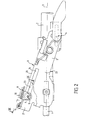
- FIGS. 3, 4, 5, 6, 7, and 8 A first detailed embodiment of the invention is shown in FIGS. 3, 4, 5, 6, 7, and 8.
- the fastening axis 7 of the windings corresponding is arranged at the end 29 of the mobile support 9 and is constituted by a rod central fixed hold 180, and by two rods lateral displaceable support 183 and 184 having each a pyrotechnic actuator 181, 182.
- Each winding 41, 42 and 43 are mounted on a roller 50 disposed on a sleeve 51 around the holding axis 5.
- Each winding 41, 42 and 43 includes a rectilinear portion 44, 45 and 46 which has substantially the same direction as the effort to amortize.
- Each straight portion 44, 45 and 46 is extends by a free end 47, 48, 49, which is bent around the holding rod 31.
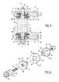
- the holding axis 5 is constituted by a rod 52, which passes through the fixed support 8 and the mobile support 9.
- the rod 52 carries a sleeve 51, which is arranged between the two respective internal faces 25 and 26 of the two lateral parts 21 and 22 of the mobile support 9.
- the rod 52 is maintained at each of its two ends 53 and 54 by a fixing assembly, which mounts on the corresponding ear 11 and 12 of the fixed support 8.
- a set of sliding of the mobile support 9 in this set of fixation is locked on each of ears 11 and 12 with a force of determined tightening.
- each fixing assembly arranged at the end of the rod 52 comprises a washer of clamping 57.
- This clamping washer 57 is disposed between the bearing face 55 or 56 of the sleeve 51 by its internal face 65, and the corresponding internal face 15 and 16 of the ears 11 and 12 of the fixed support 8.
- the clamp washer 57 includes a tube 58, which crosses the oblong hole 23, 24 of the lateral part 21, 22 corresponding to the mobile support 9.
- the rod 52 has two threaded ends 53 and 54, which pass through the through holes 64 of the tubes 58 of the washers tightening 57.
- Each threaded end 53, 54 crosses the through hole 13, 14 of the corresponding ear 11, 12 to receive a clamping nut 79, which applies to the corresponding external face 17, 18 ears 11 and 12, in order to ensure the blocking of the fixing assembly with a determined force.
- Each sliding assembly has a external washer 61 with an internal face 69 and a external face 70 and an internal washer 59 with a internal face 67 and an external face 68.
- the washer external 61 is provided with a square protuberance 62
- the internal washer 59 has a square hole 60, arranged so as to receive said square protuberance 62. From plus, the square protuberance 62 is provided with a hole passage 63 of the tube 58 of the clamping washer 57.
- the external washer 61 is disposed between the face corresponding internal 16, 18 of the ear 11, 12 corresponding of the support 8, and the external face corresponding 27, 28 of the side part 21, 22 corresponding mobile support 9.
- the washer internal 59 is arranged between the internal face corresponding 25, 26 of the lateral portion 21, 22, and the external face 66 of the clamping washer 57.
- the square protuberance 62 crosses and slides in the corresponding oblong hole 23, 24 of the movable support 9.
- the rod 52 a one threaded end 53, and the other end constituted by a head 179 applying to the corresponding ear 12 of the fixed support 8, as shown in figure 3.
- the attachment axis 7 is constituted by the rod central fixed holding 180 and the two rods lateral mobile support 183, 184 with a corresponding pyrotechnic actuator 181, 182.
- Each actuator 181, 182 is arranged and fixed on a corresponding external bearing face 73, 273 of the movable support 9.
- Movable holding rods side 183, 184 pass through a through hole corresponding 37, 38 of each of the side parts 21, 22 of the movable support 9.
- Each retaining rod lateral mobile 183, 184 is supported by a bearing corresponding 81 and 82, which belongs to a stirrup 80. This stirrup 80 is mounted and fixed on the portion of connection 20 of the end 29 of the mobile support 9.
- the central fixed retaining rod 180 is supported by the two bearings 81 and 82.
- a closure element 90 of the stirrup 80 surrounds the assembly formed by the end 29 of the mobile support 9, by the bracket 80, and by the free ends 47, 48 and 49 of the windings 41, 42 and 43. This closure element 90 is assembled with the mobile support 9 and with the bracket 80.
- the mounting of the bracket 80 with the element of closure 90 is shown in detail in the figures 7 and 8.
- the end 29 of the mobile support element 9 includes two through slots 74 and 75, and one tenon 76 with a hole 77.
- the stirrup 80 is composed a base 83 with a bearing 81, 82 at each of its ends. Each bearing 81, 82 has a hole 85, 86 for the passage and the support of the rod support 31.
- the base 83 is pierced with a flared hole 84 for the passage of the tenon 76.
- the bearings 81 and 82 engage in the through slots 74 and 75, and the end of the tenon 76 is folded over the flare 89 of the hole 84 to obtain a flare 78.
- the closing element 90 is composed of two wings 91 and 92 substantially parallel, which are connected by a bottom 93, with stiffeners 99 to the outside of the two wings 91 and 92 and the bottom 93.
- Two through slots 95 and 96 are fitted on wing 92 and bottom 93.
- Wing 91 has a tenon 94, which engages in hole 77 of tenon 76, and the ends 87 and 88 of the bearings 81 and 82 penetrate through through slots 95 and 96.
- the lateral faces 97 and 98 of the element of closure 90 slide respectively between the internal bearing faces 71 and 72 of the end 29 of the movable support element 9.
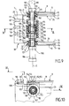
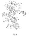
- FIG. 9 A second embodiment of the invention is shown in Figures 9, 10, 11, 12, 13 and 14.
- the holding axis 5 is constituted by a fixed holding rod 189 and by two rods of lateral mobile supports 187 and 188 each having a pyrotechnic actuator 185, 186 arranged in the fixed support 8.
- the attachment axis 7 is arranged at the end 39 of the mobile support 9.
- the fixed support has through holes 13, 14 of the holding pin 5, which is arranged on the ears 11 and 12 secured to the base 19 of the fixed support 8.
- the mobile support 9 has lateral parts 21 and 22 and a connection part 20. Each of the lateral parts 21, 22 a, at its upper part, an oblong hole 25, 26 for passing the holding axis 5 and having a length corresponding to the stroke of energy recovery.
- Three windings 101, 102, and 103 are each mounted on a roller 111, 112, 113.
- the two rollers 111 and 113 are mounted on a thin tube 160 in which the rods slide lateral movable support 187 and 188.
- the roller 112 is mounted on the central fixed retaining rod 189, which is arranged on the thin tube 160.
- Each of the windings 101, 102 and 103 includes a portion respective rectilinear 104, 105 and 106, which has substantially the same direction as the effort to be amortized and is extended by a free end 107, 108, 109, curved around the attachment axis 7.
- Both rollers 111 and 113 each include a hole 114, 116, and are mounted on the thin tube 160, in which slide the movable holding rods side 187 and 188.
- the holding axis 5 is constituted by the thin tube 160, the central fixed retaining rod 189, and each of the two movable lateral holding rods 187 and 188 with its pyrotechnic actuator 185, 186.
- Each pyrotechnic actuator 185, 186 is arranged and fixed on the external face 17, 18 of the corresponding ear 11, 12 of the fixed support 8.
- the holding axis 5 includes each of its two ends a fixing set, which is arranged in the corresponding ear 11, 12 of the element fixed support 8.
- a sliding assembly of the corresponding side part 21, 22 of the support 9, is arranged in each of these sets of fixation.
- Each fixing set is locked on each of ears 11 and 12 with force determined.
- the movable holding rod lateral 187, 188 crosses or engages in the corresponding fixing assembly.
- each mounting assembly includes a metal tube 121, which passes through the hole oblong 23 and 24 of the corresponding side part 21 and 22 of the mobile support 9.
- this tube metallic 121 passes through the through hole 13, 14 of the corresponding ear 11, 12 of the fixed support 8.
- a internal flaring 122 is arranged on the side of said side portion 21, 22 corresponding, and a external flare 123 is arranged on the side of said corresponding ear 11, 12, in order to ensure the locking of the fixing assembly.
- the tube metal 121 has a through hole 124 in the retaining rod 32.
- Each sliding assembly has a external washer 131 with an internal face 139 and a external face 138 and an internal washer 125 with a internal face 137 and an external face 136.
- the washer external 131 is provided with a half square protuberance 132 and a through hole 133.
- the internal washer 125 also has a half protuberance square 126 and a through hole 127.
- Each half protuberance 126, 132 respectively fits into the other washer 131, 125 using studs 128, 134, which fit into holes 129, 135 to form a square protuberance.
- the outer washer 131 is arranged between the corresponding ear 11, 12 of the fixed support 8, and the corresponding side part 21, 22 of the support movable 9.
- the internal washer 125 is disposed between the corresponding side part 21, 22 and the internal flaring 122 of the metal tube 121.
- the square protuberance crosses and slides in the hole oblong 23, 24 corresponding to the lateral portion 21, 22 of the mobile support 9.
- the thin tube 160, the fixed holding rod central 189, and the movable holding rods side 187 and 188 are supported by four bearings 141, 142, 143 and 144, which belong to a stirrup 140.
- This stirrup 140 is mounted and fixed under the base 19 of the fixed support 8.
- the base 19 of the fixed support 8 comprises two flared holes 152 and 153 with a flare 154 and 155.
- the stirrup 140 is composed of a base 145 with four stages 141, 142, 143 and 144. Each of these bearings has a hole 156, 157, 158 and 159 for the mounting of the thin tube 160, which is provided with precuts 161 and 162.
- the base 145 is provided with two studs 146 and 147 with a hole 148 and 149, which engage in the two flared holes 152 and 153. The end of each of the posts 146 and 147 is folded over the flare 154 and 155 of the holes 152 and 153 to obtain the flare 150 and 151.
- the fastening axis 7 includes three notches semi-circulars 117, 118, 119 arranged on the edge of the connection portion 20 belonging to the end 39 of the mobile support 9, each notch 117, 118, 119 receiving the free end 107, 108, 109 of the corresponding winding 101, 102, 103, said free end bending in the notch corresponding.
- the embodiment shown in the figure 15 relates to an energy absorption device modular, which is arranged at the end 39 of the support mobile 9.
- This device comprises three windings 191, 192 and 193, which have a horizontal holding and a vertical hanging.
- the three windings 191, 192 and 193 are mounted on a roller 50, which is arranged about a substantially horizontal holding axis 5.
- the winding holding assembly can be similar to that shown in Figure 3.
- Each winding 191, 192 and 193 includes a portion corresponding straight lines 194, 195 and 196, which has substantially the same direction as the effort to be amortized and which is extended by a free end 197, 198 and 199, bent around a fastening axis 264, 265 and 266.
- Each attachment axis consists of a movable holding rod 204, 205 and 206, substantially vertical.
- the movable holding rods 204, 205 and 206 each have a pyrotechnic actuator 201, 202 and 203, which is fixed in the connection portion 20 of the mobile support 9, using a threaded part.
- the pyrotechnic actuators are arranged above of the mobile support 9.
- the pyrotechnic actuators 201, 202 and 203 are arranged below the mobile support 9.
- the windings 191, 192 and 193 are arranged in the same so that in figure 15.
- the modular energy absorption device shown in Figure 17 includes three windings 211, 212 and 213, which have a holding vertical and vertical hanging.
- the three windings 211, 212 and 213 are each mounted on a corresponding roller 214, 215 and 216, which is arranged around a substantially holding axis vertical corresponding 207, 208 and 209.
- Each winding 211, 212 and 213 includes a part corresponding straight lines 194, 195 and 196, which has substantially the same direction as the effort to be amortized and which is extended by a free end 197, 198 and 199, bent around a fastening axis 264, 265 and 266.
- Each attachment axis consists of a movable retaining rod 204, 205 and 206, which is substantially vertical.
- Movable holding rods 204, 205 and 206 each have an actuator pyrotechnic 201, 202 and 203, which is fixed in the connection portion 20 of the mobile support 9, to using a threaded part.
- the actuators pyrotechnics are arranged below the support mobile 9; they can also be arranged above as in figure 15.
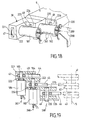
- the embodiment shown in the Figures 18 and 19 relates to a device of modular energy absorption, which is arranged to the end 39 of the mobile support 9.
- This device includes three windings 41, 42 and 43, which have a horizontal holding and horizontal hanging.
- the three windings 41, 42 and 43 are mounted on a roller 50, which is arranged around a holding axis 5 substantially horizontal.
- the outfit for windings can be similar to that shown in Figure 3.
- Each winding 41, 42 and 43 includes a straight portion 44, 45 and 46, which has substantially the same direction as the effort to be amortized and which is extended by a free end 47, 48 and 49 bent around a fastening axis 267, 268 and 269, substantially horizontal.
- An attachment pin 269 consists of a fixed retaining rod 220, which is supported by two bearings 225 and 226. Both other attachment axes 267 and 268 are formed each by a movable retaining rod 183 and 184, which is supported by two corresponding bearings 221, 222 and 223, 224. Movable holding rods 183 and 184 each have a pyrotechnic actuator 181, 182, which is fixed on the bearing wall correspondent 222, 224.
- Each winding 231, 232 and 233 includes a straight portion corresponding 44, 45 and 46, which has substantially the same direction as the effort to be amortized and which is extends by a free end 47, 48 and 49, bent around a fastening axis 267, 268 and 269, substantially horizontal.
- An attachment pin 269 consists of a fixed retaining rod 220, which is supported by two bearings 225 and 226. Both other attachment axes 267 and 268 are formed each by a movable retaining rod 183, 184, which is supported by two bearings 221, 222 and 223, 224.
- the movable holding rods 183 and 184 each have a pyrotechnic actuator 181, 182, which is fixed on the wall of the corresponding bearing 222, 224.
- the embodiments represented on the Figures 20, 21 and 22 relate to a device of modular energy absorption, which is arranged to the end 39 of the mobile support 9, and on the structure of the fixed support 8 which includes a section U-shaped with an upper side portion and a lower side portion.
- the windings have a vertical hold and horizontal hanging.
- three windings 231, 232 and 233 are each mounted on a corresponding roller 244, 245 and 246, which is arranged around a holding axis corresponding 241, 242 and 243 substantially vertical.
- Each winding 231, 232 and 233 comprises a straight portion 234, 235 and 236, which has substantially the same direction as the effort to be amortized and which is extended by a free end 237, 238 and 239, bent around a single axis hooking 7, which is substantially horizontal.
- the central winding 232 is hooked on a fixed retaining rod 180, supported by two central landings 248 and 249.
- each lateral winding 231, 233 takes place on a rod corresponding movable hold 183, 184, which is supported by a corresponding lateral bearing 247, 250, and by the corresponding central bearing 248, 249.
- the movable holding rods 183 and 184 each have a pyrotechnic actuator 181, 182, which is fixed on the wall of the corresponding bearing 247, 250.
- three windings 231, 232 and 233 are each mounted on a corresponding roller 244, 245 and 246, which is arranged around a holding axis corresponding 241, 242 and 243 substantially vertical.
- the holding of the central winding 232 is made up by a fixed retaining rod 252, which is supported by two central bearings 256 and 257.
- the holding of each lateral winding 231, 233 is constituted by a corresponding movable retaining rod 251, 253, which is supported by two lateral bearings correspondents 254, 255 and 258, 259.
- Each winding 231, 232 and 233 includes a portion corresponding rectilinear 234, 235 and 236, which has substantially the same direction as the effort to be amortized and which is extended by a free end 237, 238 and 239, bent around a single axis hooking 7, which is substantially horizontal.
- the attachment takes place on a fixed retaining rod 262, which is supported by two central bearings 248 and 249, and by two lateral bearings 247 and 250.
- the movable holding rods 251 and 253 each have a corresponding pyrotechnic actuator 261, 263, which is fixed below and on the side portion lower. They can also be fixed above and on the upper side portion.
- the central landing 256 and the two lateral bearings 254 and 258 are arranged in the upper lateral portion.
- the central bearing 257 and the two lateral bearings 255 and 259 are arranged in the lateral portion lower.
- three windings 231, 232 and 233 are each mounted on a corresponding roller 244, 245 and 246, which is arranged around a holding axis corresponding 241, 242 and 243 substantially vertical.
- the holding of the central winding 232 takes place on a fixed support rod 252, which is supported by two central landings 256 and 257.
- the holding of the first lateral winding 231 takes place on a rod mobile support 251, which is supported by two lateral bearings 254 and 255.
- the holding of the second side winding 233 consists of a rod fixed support 260, which is supported by two lateral bearings 258 and 259.
- Each winding 231, 232 and 233 includes a straight portion 234, 235 and 236, which has substantially the same direction as the effort to be amortized and which is extended by a free end 237, 238 and 239, bent around of one and the same attachment pin 7, which is substantially horizontal.
- the hanging of the central winding 232 takes place on a rod of fixed support 180, supported by two bearings central 248 and 249.
- the attachment of the first lateral winding 231 takes place on a rod fixed support 270, which is supported by a bearing corresponding side 247 and through the central landing correspondent 248.
- the hanging of the second lateral winding 233 takes place on a rod mobile support 184 supported by a lateral bearing corresponding 250 and through the central landing corresponding 249.
- the movable holding rods 184 and 251 each have a pyrotechnic actuator 182, 261.
- the three windings 41, 42, 43, etc ... have straight parts 44, 45, 46, etc ... of different lengths, with holding axes or attachment according to the cases which are axially offset from each other in the direction of movement of the movable support 9. These differences in winding length allow to further modulate the absorption of energy in the event of an impact.
- actuators pyrotechnics that are used for the determination of the number and / or length of windings concerned with energy absorption shock, is the brevity of their response time.
- the control of a pyrotechnic actuator therefore makes it possible to move the axis almost instantly, in the event of a shock holding or hanging the winding correspondent who is released and does not participate in absorption of shock energy.
Landscapes
- Engineering & Computer Science (AREA)
- Chemical & Material Sciences (AREA)
- Combustion & Propulsion (AREA)
- Transportation (AREA)
- Mechanical Engineering (AREA)
- Steering Controls (AREA)
- Mutual Connection Of Rods And Tubes (AREA)
- Seats For Vehicles (AREA)
- Transmission Devices (AREA)
Applications Claiming Priority (2)
| Application Number | Priority Date | Filing Date | Title |
|---|---|---|---|
| FR9914813 | 1999-11-19 | ||
| FR9914813A FR2801269B1 (fr) | 1999-11-19 | 1999-11-19 | Dispositif d'absorption d'energie modulaire a charges pyrotechniques d'une colonne de direction de vehicule automobile |
Publications (2)
| Publication Number | Publication Date |
|---|---|
| EP1101687A1 true EP1101687A1 (de) | 2001-05-23 |
| EP1101687B1 EP1101687B1 (de) | 2003-07-30 |
Family
ID=9552512
Family Applications (1)
| Application Number | Title | Priority Date | Filing Date |
|---|---|---|---|
| EP00403021A Expired - Lifetime EP1101687B1 (de) | 1999-11-19 | 2000-10-27 | Pyrotechnisch einstellbare Kraftfahrzeug- Lenksäulenenergieabsorptionseinrichtung |
Country Status (7)
| Country | Link |
|---|---|
| US (1) | US6367840B1 (de) |
| EP (1) | EP1101687B1 (de) |
| JP (1) | JP4457488B2 (de) |
| BR (1) | BR0005433A (de) |
| DE (1) | DE60004155T2 (de) |
| ES (1) | ES2198265T3 (de) |
| FR (1) | FR2801269B1 (de) |
Cited By (5)
| Publication number | Priority date | Publication date | Assignee | Title |
|---|---|---|---|---|
| EP1176082A1 (de) * | 2000-07-26 | 2002-01-30 | NACAM France S.A. | Pyrotechnisch einstellbare Energieabsorptionseinrichtung längs der Achse eines Kraftfahrzeuglenksäules |
| EP1184253A1 (de) * | 2000-08-29 | 2002-03-06 | Nsk Ltd | Stossenergie aufnehmende Lenksäule |
| DE10346031B4 (de) * | 2002-10-04 | 2006-06-08 | Pyroalliance | Energie aufnehmende Vorrichtung, insbesondere für Lenksäulen |
| FR2881707A1 (fr) * | 2005-02-08 | 2006-08-11 | Nacam France Sas | Dispositif d'absorption instantanee d'energie d'une colonne de direction de vehicule automobile |
| EP3326867A1 (de) * | 2016-11-25 | 2018-05-30 | Przemyslowy Instytut Motoryzacji | Intelligenter energiedämpfer |
Families Citing this family (24)
| Publication number | Priority date | Publication date | Assignee | Title |
|---|---|---|---|---|
| JP3900924B2 (ja) * | 2001-04-03 | 2007-04-04 | トヨタ自動車株式会社 | ステアリング装置の支持機構 |
| US6749222B2 (en) * | 2001-10-19 | 2004-06-15 | Delphi Technologies, Inc. | Responsive energy absorbing device for steering columns |
| US6908110B2 (en) * | 2002-03-28 | 2005-06-21 | Delphi Technologies, Inc. | Programmable energy absorbing system |
| JP4134601B2 (ja) * | 2002-06-04 | 2008-08-20 | 日本精工株式会社 | 車両用チルト式ステアリングコラム装置 |
| AU2003246136A1 (en) * | 2002-07-02 | 2004-01-23 | Nsk Ltd. | Shock absorbing steering column device for vehicle |
| DE10230442B3 (de) * | 2002-07-06 | 2004-02-19 | Daimlerchrysler Ag | Kraftübertragungselement |
| FR2855140B1 (fr) * | 2003-05-19 | 2006-05-26 | Nacam | Dispositif d'absorption modulable d'energie a charges pyrotechniques d'une colonne de direction de vehicule automobile |
| FR2857313B1 (fr) * | 2003-07-10 | 2006-11-24 | Pyroalliance | Dispositif d'amortissement du deplacement d'une piece impliquant un fil metallique |
| US7077432B2 (en) * | 2003-09-30 | 2006-07-18 | Delphi Technologies, Inc. | Steering column assembly having break-away device |
| US7229096B2 (en) * | 2004-05-06 | 2007-06-12 | Delphi Technologies, Inc. | Adaptive energy absorbing system using pin pullers |
| US7178834B2 (en) * | 2004-05-06 | 2007-02-20 | Delphi Technologies, Inc. | Adaptive release capsule for steering column |
| JP4449600B2 (ja) * | 2004-06-28 | 2010-04-14 | アイシン精機株式会社 | 衝撃吸収式ステアリング装置 |
| FR2872474B1 (fr) | 2004-07-05 | 2006-08-18 | Nacam France Sas | Dispositif d'absorption d'energie modulable en deux zones d'une colonne de direction de vehicule automobile |
| DE102004042283B4 (de) * | 2004-09-01 | 2009-03-19 | Daimler Ag | Lenksäulenanordnung |
| US7827880B2 (en) * | 2005-03-21 | 2010-11-09 | Gm Global Technology Operations, Inc. | Steering column assembly with a quick release bolt |
| JP2007062441A (ja) * | 2005-08-29 | 2007-03-15 | Fuji Kiko Co Ltd | 車両用ステアリングコラム装置 |
| JP4205687B2 (ja) * | 2005-03-31 | 2009-01-07 | 株式会社山田製作所 | ステアリング装置 |
| US7510213B2 (en) * | 2005-06-01 | 2009-03-31 | Delphi Technologies, Inc. | Adaptive energy absorber for steering column |
| US20060273568A1 (en) * | 2005-06-01 | 2006-12-07 | Manwaring Marvin V | Adaptive energy absorber for steering column |
| US20070085317A1 (en) * | 2005-10-17 | 2007-04-19 | Delphi Technologies, Inc. | Steering column mounting |
| TWI292089B (en) * | 2006-04-24 | 2008-01-01 | Quanta Comp Inc | Dissipation module |
| KR101424877B1 (ko) * | 2012-08-16 | 2014-08-01 | 주식회사 만도 | 자동차의 조향 컬럼 |
| JP6239875B2 (ja) * | 2013-06-28 | 2017-11-29 | 株式会社ジェイテクト | ステアリング装置 |
| WO2016167670A1 (en) * | 2015-04-17 | 2016-10-20 | University Of Canterbury | Energy dissipation device |
Citations (3)
| Publication number | Priority date | Publication date | Assignee | Title |
|---|---|---|---|---|
| DE19510615A1 (de) * | 1995-03-23 | 1996-09-26 | Lemfoerder Metallwaren Ag | Befestigung einer Lenksäule in einem Kraftfahrzeug |
| FR2775647A1 (fr) * | 1998-03-03 | 1999-09-10 | Lemforder Nacam Sa | Dispositif d''absorption d'energie a enroulement spirale pour colonne de direction de vehicule automobile |
| FR2788029A1 (fr) * | 1999-01-06 | 2000-07-07 | Lemforder Nacam Sa | Dispositif d'absorption modulable d'energie d'une colonne de direction de vehicule automobile |
Family Cites Families (7)
| Publication number | Priority date | Publication date | Assignee | Title |
|---|---|---|---|---|
| FR2714649B1 (fr) * | 1994-01-06 | 1996-03-15 | Nacam | Organe d'absorption d'énergie notamment pour colonne de direction de véhicule automobile. |
| US5720496A (en) * | 1996-06-17 | 1998-02-24 | General Motors Corporation | Energy absorber for motor vehicle steering column |
| SE507771C2 (sv) * | 1996-11-21 | 1998-07-13 | Volvo Ab | Anordning och förfarande för skydd av åkande i fordon |
| DE59809761D1 (de) * | 1997-04-16 | 2003-11-06 | Volkswagen Ag | Lenksäule für Insassenschutzeinrichtungen und Sicherheitslenkungen |
| FR2775646B1 (fr) * | 1998-03-03 | 2000-05-12 | Lemforder Nacam Sa | Dispositif d'absorption d'energie a double enroulement pour colonne de direction de vehicule automobile |
| FR2781189B1 (fr) * | 1998-07-16 | 2000-09-15 | Allibert Ind | Dispositif de protection d'un conducteur de vehicule en cas de choc de ce dernier |
| US6227571B1 (en) * | 1999-11-03 | 2001-05-08 | Trw Vehicle Safety Systems Inc. | Telescoping vehicle steering column apparatus for helping to protect a vehicle driver |
-
1999
- 1999-11-19 FR FR9914813A patent/FR2801269B1/fr not_active Expired - Lifetime
-
2000
- 2000-10-27 EP EP00403021A patent/EP1101687B1/de not_active Expired - Lifetime
- 2000-10-27 ES ES00403021T patent/ES2198265T3/es not_active Expired - Lifetime
- 2000-10-27 DE DE60004155T patent/DE60004155T2/de not_active Expired - Lifetime
- 2000-11-15 US US09/712,169 patent/US6367840B1/en not_active Expired - Fee Related
- 2000-11-17 BR BR0005433-0A patent/BR0005433A/pt not_active IP Right Cessation
- 2000-11-20 JP JP2000352872A patent/JP4457488B2/ja not_active Expired - Fee Related
Patent Citations (3)
| Publication number | Priority date | Publication date | Assignee | Title |
|---|---|---|---|---|
| DE19510615A1 (de) * | 1995-03-23 | 1996-09-26 | Lemfoerder Metallwaren Ag | Befestigung einer Lenksäule in einem Kraftfahrzeug |
| FR2775647A1 (fr) * | 1998-03-03 | 1999-09-10 | Lemforder Nacam Sa | Dispositif d''absorption d'energie a enroulement spirale pour colonne de direction de vehicule automobile |
| FR2788029A1 (fr) * | 1999-01-06 | 2000-07-07 | Lemforder Nacam Sa | Dispositif d'absorption modulable d'energie d'une colonne de direction de vehicule automobile |
Non-Patent Citations (1)
| Title |
|---|
| ANONYMUS: "COMPUTER CONTROLLED ENERGY ABSORBING STEERING COLUMN FOR AUTOMOTIVE USE", RESEARCH DISCLOSURE, no. 359, 1 March 1994 (1994-03-01), INDUSTRIAL OPPORTUNITIES LTD. HAVANT., GB, pages 157 - 159, XP000440547, ISSN: 0374-4353 * |
Cited By (6)
| Publication number | Priority date | Publication date | Assignee | Title |
|---|---|---|---|---|
| EP1176082A1 (de) * | 2000-07-26 | 2002-01-30 | NACAM France S.A. | Pyrotechnisch einstellbare Energieabsorptionseinrichtung längs der Achse eines Kraftfahrzeuglenksäules |
| EP1184253A1 (de) * | 2000-08-29 | 2002-03-06 | Nsk Ltd | Stossenergie aufnehmende Lenksäule |
| US6631924B2 (en) | 2000-08-29 | 2003-10-14 | Nsk Ltd. | Shock absorbing type steering column apparatus |
| DE10346031B4 (de) * | 2002-10-04 | 2006-06-08 | Pyroalliance | Energie aufnehmende Vorrichtung, insbesondere für Lenksäulen |
| FR2881707A1 (fr) * | 2005-02-08 | 2006-08-11 | Nacam France Sas | Dispositif d'absorption instantanee d'energie d'une colonne de direction de vehicule automobile |
| EP3326867A1 (de) * | 2016-11-25 | 2018-05-30 | Przemyslowy Instytut Motoryzacji | Intelligenter energiedämpfer |
Also Published As
| Publication number | Publication date |
|---|---|
| BR0005433A (pt) | 2001-07-03 |
| JP4457488B2 (ja) | 2010-04-28 |
| FR2801269B1 (fr) | 2002-02-08 |
| DE60004155T2 (de) | 2004-06-09 |
| FR2801269A1 (fr) | 2001-05-25 |
| US6367840B1 (en) | 2002-04-09 |
| EP1101687B1 (de) | 2003-07-30 |
| ES2198265T3 (es) | 2004-02-01 |
| DE60004155D1 (de) | 2003-09-04 |
| JP2001171529A (ja) | 2001-06-26 |
Similar Documents
| Publication | Publication Date | Title |
|---|---|---|
| EP1101687B1 (de) | Pyrotechnisch einstellbare Kraftfahrzeug- Lenksäulenenergieabsorptionseinrichtung | |
| EP1018463B1 (de) | Modulierbare Kraftfahrzeug-Lenksäulen- Energieabsorptionseinrichtung | |
| EP1176082B1 (de) | Pyrotechnisch einstellbare Energieabsorptionseinrichtung längs der Achse einer Kraftfahrzeuglenksäule | |
| EP0949136B1 (de) | Energieaufnahmeeinheit mit doppelter Wicklung für eine Kraftfahrzeuglenksäule | |
| EP1479593A1 (de) | Modulierbare Kraftfahrzeug-Lenksäulen-Energieabsorptionseinrichtung mit pyrotechnischer Auslösung | |
| EP0662414B1 (de) | Energieabsorbierende Einrichtung, insbesondere für eine Kraftfahrzeuglenksäule | |
| EP0499508B1 (de) | Lenksäulen-Anordnung für ein Kraftfahrzeug | |
| EP1345804A1 (de) | Vorrichtung zum festklemmen eines einstellbaren elements bezüglich einer stützanordnung | |
| EP1127772B1 (de) | Lineare Lenksäulenführungseinrichtung | |
| EP0505470A1 (de) | Anhänger mit kombinierten mitteln zum kuppeln und zentrieren. | |
| WO2002012018A1 (fr) | Dossier de siege de vehicule automobile | |
| EP1336546B1 (de) | Einstell- Einrichtung eines Energieaufnehme-Systems einer Kraftfahrzeuglenksäule | |
| EP0930183A1 (de) | Hinterradaufhängungsvorrichtung eines Kraftfahrzeuges | |
| FR2841524A1 (fr) | Dispositif d'absorption d'energie d'une colonne de direction de vehicule automobile | |
| EP3423733B1 (de) | Schwingungsdämpfungsvorrichtung zwischen einem ersten schwingungselement und einem zweiten element | |
| EP0223640B1 (de) | Anhängbares Fahrzeug mit einer verlängerbaren Kupplung | |
| FR2875742A1 (fr) | Vehicule automobile muni d'un essieu a traverse deformable et a porte fusee de roue mobile longitudinalement | |
| EP3601016B1 (de) | Verkleidungsteil für fahrzeugkarosserie | |
| FR2663590A1 (fr) | Engin de travaux publics ou similaires comportant un chassis articule en deux parties. | |
| EP1359082A1 (de) | Positionsanpassungseinrichtung einer einstellbaren Kraftfahrzeuglenksäule | |
| FR2775648A1 (fr) | Dispositif d'absorption d'energie a double enroulement spirale pour colonne de direction de vehicule automobile | |
| EP4098498B1 (de) | Vorrichtung zum anhängen eines anhängers an ein mit einer gelenkverbindungsstruktur versehenes zugfahrzeug | |
| EP3814218B1 (de) | Fahrwerk für ein flugzeug, das weniger als 5,7 tonnen wiegt | |
| FR2775647A1 (fr) | Dispositif d''absorption d'energie a enroulement spirale pour colonne de direction de vehicule automobile | |
| FR2917037A1 (fr) | Vehicule automobile comprenant des moyens de reprise d'efforts qui comportent un corps creux dans lequel est fixe un support de fixation d'une ceinture de securite |
Legal Events
| Date | Code | Title | Description |
|---|---|---|---|
| PUAI | Public reference made under article 153(3) epc to a published international application that has entered the european phase |
Free format text: ORIGINAL CODE: 0009012 |
|
| AK | Designated contracting states |
Kind code of ref document: A1 Designated state(s): DE ES GB IT SE |
|
| AX | Request for extension of the european patent |
Free format text: AL;LT;LV;MK;RO;SI |
|
| 17P | Request for examination filed |
Effective date: 20010702 |
|
| AKX | Designation fees paid |
Free format text: DE ES GB IT SE |
|
| GRAH | Despatch of communication of intention to grant a patent |
Free format text: ORIGINAL CODE: EPIDOS IGRA |
|
| GRAH | Despatch of communication of intention to grant a patent |
Free format text: ORIGINAL CODE: EPIDOS IGRA |
|
| GRAH | Despatch of communication of intention to grant a patent |
Free format text: ORIGINAL CODE: EPIDOS IGRA |
|
| GRAA | (expected) grant |
Free format text: ORIGINAL CODE: 0009210 |
|
| AK | Designated contracting states |
Designated state(s): DE ES GB IT SE |
|
| REG | Reference to a national code |
Ref country code: GB Ref legal event code: FG4D Free format text: NOT ENGLISH |
|
| REG | Reference to a national code |
Ref country code: SE Ref legal event code: TRGR |
|
| REF | Corresponds to: |
Ref document number: 60004155 Country of ref document: DE Date of ref document: 20030904 Kind code of ref document: P |
|
| GBT | Gb: translation of ep patent filed (gb section 77(6)(a)/1977) | ||
| REG | Reference to a national code |
Ref country code: ES Ref legal event code: FG2A Ref document number: 2198265 Country of ref document: ES Kind code of ref document: T3 |
|
| PLBE | No opposition filed within time limit |
Free format text: ORIGINAL CODE: 0009261 |
|
| STAA | Information on the status of an ep patent application or granted ep patent |
Free format text: STATUS: NO OPPOSITION FILED WITHIN TIME LIMIT |
|
| 26N | No opposition filed |
Effective date: 20040504 |
|
| PGFP | Annual fee paid to national office [announced via postgrant information from national office to epo] |
Ref country code: SE Payment date: 20051013 Year of fee payment: 6 |
|
| PGFP | Annual fee paid to national office [announced via postgrant information from national office to epo] |
Ref country code: ES Payment date: 20051018 Year of fee payment: 6 |
|
| PG25 | Lapsed in a contracting state [announced via postgrant information from national office to epo] |
Ref country code: SE Free format text: LAPSE BECAUSE OF NON-PAYMENT OF DUE FEES Effective date: 20061028 |
|
| PGFP | Annual fee paid to national office [announced via postgrant information from national office to epo] |
Ref country code: IT Payment date: 20061031 Year of fee payment: 7 |
|
| EUG | Se: european patent has lapsed | ||
| REG | Reference to a national code |
Ref country code: ES Ref legal event code: FD2A Effective date: 20061028 |
|
| PG25 | Lapsed in a contracting state [announced via postgrant information from national office to epo] |
Ref country code: ES Free format text: LAPSE BECAUSE OF NON-PAYMENT OF DUE FEES Effective date: 20061028 |
|
| PG25 | Lapsed in a contracting state [announced via postgrant information from national office to epo] |
Ref country code: IT Free format text: LAPSE BECAUSE OF NON-PAYMENT OF DUE FEES Effective date: 20071027 |
|
| PGFP | Annual fee paid to national office [announced via postgrant information from national office to epo] |
Ref country code: DE Payment date: 20101022 Year of fee payment: 11 |
|
| PGFP | Annual fee paid to national office [announced via postgrant information from national office to epo] |
Ref country code: GB Payment date: 20101021 Year of fee payment: 11 |
|
| REG | Reference to a national code |
Ref country code: DE Ref legal event code: R082 Ref document number: 60004155 Country of ref document: DE Representative=s name: MUELLER, JOCHEN, DIPL.-ING., DE Ref country code: DE Ref legal event code: R082 Ref document number: 60004155 Country of ref document: DE Representative=s name: JOCHEN MUELLER, DE |
|
| GBPC | Gb: european patent ceased through non-payment of renewal fee |
Effective date: 20121027 |
|
| PG25 | Lapsed in a contracting state [announced via postgrant information from national office to epo] |
Ref country code: GB Free format text: LAPSE BECAUSE OF NON-PAYMENT OF DUE FEES Effective date: 20121027 Ref country code: DE Free format text: LAPSE BECAUSE OF FAILURE TO SUBMIT A TRANSLATION OF THE DESCRIPTION OR TO PAY THE FEE WITHIN THE PRESCRIBED TIME-LIMIT Effective date: 20130501 |
|
| REG | Reference to a national code |
Ref country code: DE Ref legal event code: R119 Ref document number: 60004155 Country of ref document: DE Effective date: 20130501 |