EP1101864A2 - Procédé pour transferer une bande fibreuse - Google Patents
Procédé pour transferer une bande fibreuse Download PDFInfo
- Publication number
- EP1101864A2 EP1101864A2 EP00121725A EP00121725A EP1101864A2 EP 1101864 A2 EP1101864 A2 EP 1101864A2 EP 00121725 A EP00121725 A EP 00121725A EP 00121725 A EP00121725 A EP 00121725A EP 1101864 A2 EP1101864 A2 EP 1101864A2
- Authority
- EP
- European Patent Office
- Prior art keywords
- web
- guide roller
- transfer
- covering
- suction guide
- Prior art date
- Legal status (The legal status is an assumption and is not a legal conclusion. Google has not performed a legal analysis and makes no representation as to the accuracy of the status listed.)
- Granted
Links
- 238000000034 method Methods 0.000 title claims description 22
- 239000011111 cardboard Substances 0.000 claims abstract description 5
- 239000011087 paperboard Substances 0.000 claims abstract description 5
- 239000004744 fabric Substances 0.000 claims description 4
- 238000000926 separation method Methods 0.000 claims description 4
- 238000001035 drying Methods 0.000 abstract 2
- XLYOFNOQVPJJNP-UHFFFAOYSA-N water Substances O XLYOFNOQVPJJNP-UHFFFAOYSA-N 0.000 abstract 2
- 230000003068 static effect Effects 0.000 abstract 1
- 239000000835 fiber Substances 0.000 description 4
- 239000000123 paper Substances 0.000 description 4
- 238000010276 construction Methods 0.000 description 1
- 230000007423 decrease Effects 0.000 description 1
Images

Classifications
-
- D—TEXTILES; PAPER
- D21—PAPER-MAKING; PRODUCTION OF CELLULOSE
- D21F—PAPER-MAKING MACHINES; METHODS OF PRODUCING PAPER THEREON
- D21F3/00—Press section of machines for making continuous webs of paper
- D21F3/02—Wet presses
- D21F3/04—Arrangements thereof
- D21F3/045—Arrangements thereof including at least one extended press nip
-
- D—TEXTILES; PAPER
- D21—PAPER-MAKING; PRODUCTION OF CELLULOSE
- D21G—CALENDERS; ACCESSORIES FOR PAPER-MAKING MACHINES
- D21G9/00—Other accessories for paper-making machines
- D21G9/0063—Devices for threading a web tail through a paper-making machine
Definitions
- the present invention relates to a method for transferring a to be treated Fibrous web, in particular paper or cardboard web, from a die Endless string of fibers delivering fibrous web to a fibrous web absorbing endless string that runs around in the transfer area a suction guide roller is guided. It also relates to a device for treatment a fibrous web according to the preamble of claim 11.
- the paper web between two sections of a paper machine transfers that the web receiving, guided around a Saugleitwalze String in contact with the one on the dispensing string lying paper web is brought and the web by generating a Negative pressure in the suction guide roller from this to the receiving string brought.
- the position of the remains during this transfer process two strings, each through a sieve, a felt or a dryer can be formed, unchanged relative to each other.
- the aim of the invention is to provide a method and a device of the type mentioned at the outset which ensure a faster and safer web transfer in order to minimize production loss times.
- this object is achieved according to the invention by that the two strings relative to each other via an operating position be moved into a transfer position in which the suction guide roller guided web-absorbing covering tape in the area of the suction guide roll in the web-covering string dips that the two string after the transfer of the fibrous web relative to each other at least in are essentially moved back into the operating position. It is an advantage if at the same time the vacuum in the suction guide roller is changed so that it is larger in the transfer position than in the operating position.
- both straps should be in the transfer area in the operating position be spaced from each other.
- the web-removing covering tape is used moved accordingly to the transfer position or the operating position to reach.
- the web-covering string is preferred moved accordingly via an adjustable guide roller.
- an adjustable suction guide roller is used and via this adjustable suction guide roller only the web-absorbing covering tape moved accordingly to the transfer position or the operating position to reach.
- the fibrous web can, for example, be transferred machine-wide. It is however, it is also possible to transfer only an edge band or an edge strip.
- the vacuum in the suction guide roll for example from about -2 mWS to about - 4 mWS.
- the device according to the invention for treating a fibrous web is corresponding characterized in that at least one transfer point is provided is at which the two straps relative to each other via a Operating position can be moved into a transfer position in which the Suction guide roller guided web-receiving covering tape in the area of Suction guide roller immersed in the web-covering fabric that the two Stringing belts after transfer of the fibrous web relative to each other are at least essentially movable back into the operating position and that preferably the vacuum in the suction guide roll can be changed at the same time is that it is larger in the transfer position than in the operating position.
- both straps should be in the transfer area in the operating position be spaced from each other.
- An appropriately designed transfer point can, for example, between a former and a press, between a press and a dryer section and / or be provided between two presses. It can be an advantage if at least one press is double felted.
- presses for example with two in a row arranged presses are at least one and preferably both presses each formed by a shoe press.
- At least one correspondingly designed transfer point provided in the area of a separation point.
- the covering straps can in particular each through a sieve, a felt or a dryer fabric can be formed.
- At least one suction box can be provided within the loop of the web-covering covering tape, for example after a shoe press.
- at least one suction box can also be moved in the case of a web-dispensing covering belt which can be moved correspondingly to the web transfer.
- the vacuum in the moving suction box can preferably be changed and reduced for the web transfer.
- the suction box can, in principle, also be stationary in spite of the movable webbing covering tape. In the event that at least one stationary suction box is provided, the negative pressure in this stationary suction box is preferably kept constant.
- the invention is particularly at machine speeds above 1600 m / min and especially above 1900 m / min can be used with advantage.
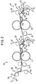
- Figures 1 and 2 each show a device 10 for treating a fibrous web 12, which is in particular a paper or cardboard web can act.
- the devices 10 each comprise two in a row in the web running direction L. arranged double felted shoe presses 14, 16, through which in the web running direction extended press nip 18 or 20, a bottom felt 22 or 24 and a Upper felt 26 or 28 is guided.
- the fibrous web 12 becomes through the upper felt 26 of the front shoe press 14 in the area of a suction guide roller 30 by a screen 32 of a former 33 or a former Screen section taken over and guided into the press nip 18.
- Behind the front shoe press 14 are the bottom felt 22 and the fibrous web 12 separated from the top wire 32 in the area of a suction guide roller 34. In the area this separation point, the fibrous web 12 from the bottom felt 22 to the Pass the upper felt 28 of the rear shoe press 16 to the transfer area a suction guide roller 36 is guided.
- the bottom felt 22 is thus as a web-releasing Covering tape and the upper felt 28 as a web-receiving covering tape to watch.
- the fibrous web 12 is then fed through the top felt 28 into the Press nip 20 of the rear shoe press 16 performed.
- the bottom felt 24 and the Fiber web 12 separated from the upper felt 28 in the area of a suction guide roller 38.
- the fibrous web 12 is from the bottom felt 24, for example, to a dryer 40 of a dryer section 41, which is guided in the transfer area around a suction guide roller 42.
- the bottom felt 24 is thus as a web-giving covering tape and the dry felt 40 as a web-receiving Watch the string.
- the two endless strings 22, 28 and 24, 40 relative to one another beyond an operating position into a transfer position movable in which the web-receiving end guided around the suction guide roller 36 or 42 Covering belt 28 or 40 in the area of the suction guide roller 36 or 42 in the web-covering string 22 or 24 immersed.
- the fibrous web 12 becomes the two covering bands 22, 28 and 24, 40 moved relative to each other again at least substantially in the operating position.
- the vacuum in the suction guide roller 36 or 42 is changed so that it is larger in the transfer position than in the operating position.
- the web-receiving covering tape 28 and 40 are from the web-dispensing web Stringing tape 22 or 24 spaced apart, preferably in the range of approx. 5 - 20 cm. This enables a speed difference between the strings 22 and 28 or 24 and 40 on the respective Transfer points 44 and 46 for train construction, which occurs when the fibrous web is stretched longitudinally 12 or may be necessary to build up voltage.
- Figure 2 shows a closed guide of the fibrous web 12 to ensure safe web guidance even at high speeds.
- the web-receiving end guided around the suction guide roller 36 or 42 touches String band 28 or 40 that from the web-releasing string 22 or 24 supplied fibrous web 12 at least essentially, without the fibrous web 12 and the web-releasing covering tape Loop around the suction guide roller.
- the suction guide roller is stationary 36 and 42, respectively, the webbing covering tape 22 and 24 can be moved accordingly, to reach the transfer position or the operating position.
- the suction guide roller 36 or 42 is stationary.
- the two endless strings point 22, 28 or 24, 40 usually a distance from each other, so that at the beginning of the transfer process these two belts according to the execution in Figure 2 must first be merged until the web-receiving Band touches the fibrous web lying on the web-dispensing belt. Subsequently, the transfer process can be carried out in the manner described to be continued.
- a correspondingly designed transfer point can also be used, for example also be provided between the former 33 and the press 14.
- FIG. 2 differs from that according to FIG. 1 further by the fact that 22 or 24 each have two suction boxes 52, 54 and 56 to which vacuum can be applied, 58 are provided. There is a suction box 52 and 56 between each Shoe press 14 or 16 and the subsequent suction guide roller 34 or 38 and a suction box 54 and 58 between the two suction guide rollers 34, 36 and 38, 42 arranged. These suction boxes are used to avoid rewetting after the shoe press 14 or 16.
- the second suction box 54 or 58 can also be moved become.
- the vacuum in the moving suction box 54 or 58 can be changeable, wherein it is preferably reduced to the web transfer to promote the railway levy.
- the second suction box 54 or 58 can also be kept stationary. Especially in the case of one stationary arrangement, the vacuum in the suction box 54 or 58 can also be constant be held because the holding force generated by moving the Bottom felt 22 or 24 decreases and thus the fibrous web 12 is removed more easily can be.
- the first suction box 52 or 56 is usually stationary.
Landscapes
- Paper (AREA)
- Preliminary Treatment Of Fibers (AREA)
- Replacement Of Web Rolls (AREA)
Applications Claiming Priority (4)
| Application Number | Priority Date | Filing Date | Title |
|---|---|---|---|
| DE1999155030 DE19955030A1 (de) | 1999-11-16 | 1999-11-16 | Verfahren zum Überführen einer zu behandelnden Faserstoffbahn |
| DE19955030 | 1999-11-16 | ||
| DE10015357 | 2000-03-28 | ||
| DE2000115357 DE10015357A1 (de) | 2000-03-28 | 2000-03-28 | Bahnabnahmeanordnung |
Publications (3)
| Publication Number | Publication Date |
|---|---|
| EP1101864A2 true EP1101864A2 (fr) | 2001-05-23 |
| EP1101864A3 EP1101864A3 (fr) | 2002-11-13 |
| EP1101864B1 EP1101864B1 (fr) | 2005-03-02 |
Family
ID=26005059
Family Applications (1)
| Application Number | Title | Priority Date | Filing Date |
|---|---|---|---|
| EP00121725A Expired - Lifetime EP1101864B1 (fr) | 1999-11-16 | 2000-10-05 | Procédé pour transferer une bande fibreuse |
Country Status (2)
| Country | Link |
|---|---|
| EP (1) | EP1101864B1 (fr) |
| DE (1) | DE50009627D1 (fr) |
Cited By (1)
| Publication number | Priority date | Publication date | Assignee | Title |
|---|---|---|---|---|
| EP1493863A1 (fr) * | 2003-07-02 | 2005-01-05 | Metso Paper, Inc. | Dispositif de régulation d'une bande dans la section de pressage d'une machine à papier ou carton |
Family Cites Families (5)
| Publication number | Priority date | Publication date | Assignee | Title |
|---|---|---|---|---|
| US3708389A (en) * | 1968-12-02 | 1973-01-02 | Beloit Corp | Web pickup arrangement for papermaking machines |
| US4854053A (en) * | 1987-04-30 | 1989-08-08 | Beloit Corporation | Transfer apparatus |
| DE9001209U1 (de) * | 1990-02-03 | 1990-04-05 | J.M. Voith Gmbh, 7920 Heidenheim | Trockenpartie |
| DE4124648A1 (de) * | 1991-07-25 | 1993-01-28 | Escher Wyss Gmbh | Einrichtung zur verbindung zweier trockengruppen einer papiermaschine |
| DE19511988C1 (de) * | 1995-03-31 | 1996-08-01 | Voith Sulzer Papiermasch Gmbh | Pressenpartie für eine Papiermaschine |
-
2000
- 2000-10-05 DE DE50009627T patent/DE50009627D1/de not_active Expired - Lifetime
- 2000-10-05 EP EP00121725A patent/EP1101864B1/fr not_active Expired - Lifetime
Cited By (3)
| Publication number | Priority date | Publication date | Assignee | Title |
|---|---|---|---|---|
| EP1493863A1 (fr) * | 2003-07-02 | 2005-01-05 | Metso Paper, Inc. | Dispositif de régulation d'une bande dans la section de pressage d'une machine à papier ou carton |
| US7294236B2 (en) | 2003-07-02 | 2007-11-13 | Metso Paper, Inc. | Arrangement for controlling the web in a press section of a paper or board machine |
| CN100519927C (zh) * | 2003-07-02 | 2009-07-29 | 美卓纸业公司 | 在纸机或纸板机的压榨部控制纸幅的装置 |
Also Published As
| Publication number | Publication date |
|---|---|
| EP1101864A3 (fr) | 2002-11-13 |
| DE50009627D1 (de) | 2005-04-07 |
| EP1101864B1 (fr) | 2005-03-02 |
Similar Documents
| Publication | Publication Date | Title |
|---|---|---|
| DE3784079T2 (de) | Vorrichtung zur trocknung einer bahn. | |
| DE69019728T2 (de) | Vorrichtung zum Trocknen einer Bahn. | |
| DE4224730C1 (en) | Tissue paper mfg. machine preventing moisture return - comprises shoe press for press unit(s) for drying tissue web, for min. press units | |
| EP0509199B2 (fr) | Section de presse pour une machine à papier | |
| DE4244884C2 (de) | Maschine zur Herstellung einer Faserstoffbahn | |
| EP0775777A2 (fr) | Calandre pour machine à papier ou machine de couchage | |
| EP1225270A2 (fr) | Procédé pour le conditionnement d' une bande en mouvement | |
| DE69304469T2 (de) | Papiermaschine mit einem Einfädelsystem in der Presspartie | |
| EP0857818B1 (fr) | Machine pour la fabrication d'une bande fibreuse | |
| DE19713645A1 (de) | Verfahren zum Transportieren einer Faserstoffbahn sowie Vorrichtung zur Durchführung des Verfahrens | |
| EP1101864B1 (fr) | Procédé pour transferer une bande fibreuse | |
| AT521367B1 (de) | Vorrichtung und verfahren zum überführen eines streifens einer bahn | |
| WO2006114343A1 (fr) | Machine pour produire une bande de matiere fibreuse | |
| EP0870866B1 (fr) | Appareil et procédé pour la déshumidification d'une bande | |
| EP0751255A1 (fr) | Dispositif pour la déshumidification d'une bande fibreuse | |
| EP1739228B1 (fr) | Machine pour fabriquer une bande fibreuse | |
| WO1995020068A1 (fr) | Transport sans traction d'une bande dans une section de compression | |
| DE10027352A1 (de) | Verfahren für einen Papierbahntransfer und Transfervorrichtung für eine Papierbahn | |
| DE19955030A1 (de) | Verfahren zum Überführen einer zu behandelnden Faserstoffbahn | |
| AT521368B1 (de) | Vorrichtung und verfahren zum überführen eines streifens einer bahn | |
| EP1158093A2 (fr) | Dispositif pour la fabrication d'une bande fibreuse multi-couches | |
| DE4335024C2 (de) | Pressenpartie einer Papiermaschine und Überführeinrichtung | |
| EP3833816A1 (fr) | Système de presse | |
| DE29924918U1 (de) | Vorrichtung zum Überführen einer zu behandelnden Faserstoffbahn | |
| AT520825B1 (de) | Vorrichtung und Verfahren zum Überführen eines Streifens einer Bahn |
Legal Events
| Date | Code | Title | Description |
|---|---|---|---|
| PUAI | Public reference made under article 153(3) epc to a published international application that has entered the european phase |
Free format text: ORIGINAL CODE: 0009012 |
|
| AK | Designated contracting states |
Kind code of ref document: A2 Designated state(s): AT BE CH CY DE DK ES FI FR GB GR IE IT LI LU MC NL PT SE |
|
| AX | Request for extension of the european patent |
Free format text: AL;LT;LV;MK;RO;SI |
|
| PUAL | Search report despatched |
Free format text: ORIGINAL CODE: 0009013 |
|
| AK | Designated contracting states |
Kind code of ref document: A3 Designated state(s): AT BE CH CY DE DK ES FI FR GB GR IE IT LI LU MC NL PT SE |
|
| AX | Request for extension of the european patent |
Free format text: AL;LT;LV;MK;RO;SI |
|
| 17P | Request for examination filed |
Effective date: 20030513 |
|
| AKX | Designation fees paid |
Designated state(s): DE FI SE |
|
| 17Q | First examination report despatched |
Effective date: 20040127 |
|
| GRAP | Despatch of communication of intention to grant a patent |
Free format text: ORIGINAL CODE: EPIDOSNIGR1 |
|
| GRAS | Grant fee paid |
Free format text: ORIGINAL CODE: EPIDOSNIGR3 |
|
| GRAA | (expected) grant |
Free format text: ORIGINAL CODE: 0009210 |
|
| AK | Designated contracting states |
Kind code of ref document: B1 Designated state(s): DE FI SE |
|
| REG | Reference to a national code |
Ref country code: SE Ref legal event code: TRGR |
|
| REG | Reference to a national code |
Ref country code: IE Ref legal event code: FG4D Free format text: GERMAN |
|
| REF | Corresponds to: |
Ref document number: 50009627 Country of ref document: DE Date of ref document: 20050407 Kind code of ref document: P |
|
| PLBE | No opposition filed within time limit |
Free format text: ORIGINAL CODE: 0009261 |
|
| STAA | Information on the status of an ep patent application or granted ep patent |
Free format text: STATUS: NO OPPOSITION FILED WITHIN TIME LIMIT |
|
| 26N | No opposition filed |
Effective date: 20051205 |
|
| PGFP | Annual fee paid to national office [announced via postgrant information from national office to epo] |
Ref country code: SE Payment date: 20091014 Year of fee payment: 10 |
|
| PG25 | Lapsed in a contracting state [announced via postgrant information from national office to epo] |
Ref country code: SE Free format text: LAPSE BECAUSE OF NON-PAYMENT OF DUE FEES Effective date: 20101006 |
|
| PGFP | Annual fee paid to national office [announced via postgrant information from national office to epo] |
Ref country code: DE Payment date: 20191021 Year of fee payment: 20 Ref country code: FI Payment date: 20191022 Year of fee payment: 20 |
|
| REG | Reference to a national code |
Ref country code: DE Ref legal event code: R071 Ref document number: 50009627 Country of ref document: DE |
|
| REG | Reference to a national code |
Ref country code: FI Ref legal event code: MAE |