EP1101896A2 - Fenêtre à lamelles - Google Patents
Fenêtre à lamelles Download PDFInfo
- Publication number
- EP1101896A2 EP1101896A2 EP00124915A EP00124915A EP1101896A2 EP 1101896 A2 EP1101896 A2 EP 1101896A2 EP 00124915 A EP00124915 A EP 00124915A EP 00124915 A EP00124915 A EP 00124915A EP 1101896 A2 EP1101896 A2 EP 1101896A2
- Authority
- EP
- European Patent Office
- Prior art keywords
- push rod
- louvre window
- chamber
- window according
- outer frame
- Prior art date
- Legal status (The legal status is an assumption and is not a legal conclusion. Google has not performed a legal analysis and makes no representation as to the accuracy of the status listed.)
- Granted
Links
Images



Classifications
-
- E—FIXED CONSTRUCTIONS
- E06—DOORS, WINDOWS, SHUTTERS, OR ROLLER BLINDS IN GENERAL; LADDERS
- E06B—FIXED OR MOVABLE CLOSURES FOR OPENINGS IN BUILDINGS, VEHICLES, FENCES OR LIKE ENCLOSURES IN GENERAL, e.g. DOORS, WINDOWS, BLINDS, GATES
- E06B7/00—Special arrangements or measures in connection with doors or windows
- E06B7/02—Special arrangements or measures in connection with doors or windows for providing ventilation, e.g. through double windows; Arrangement of ventilation roses
- E06B7/08—Louvre doors, windows or grilles
- E06B7/084—Louvre doors, windows or grilles with rotatable lamellae
- E06B7/086—Louvre doors, windows or grilles with rotatable lamellae interconnected for concurrent movement
Definitions
- the invention relates to a louvre window with an outer and a Inside and with an outer frame consisting of an upper one left, a right and a lower side part, in which Outer frame several slats arranged one above the other in the longitudinal axis of the Slat with its shaft are rotatably held in a bearing
- the louvre window is closed, the louvres are aligned and the individual slats when the louvre window is open can be moved together, all slats being connected by a common connecting rod attached within the outer frame connected are and by the movement of the push rod in one or in the open or close the louvre window in the other direction.
- Such a louvre window is already known. So in DE-OS 40th 30 627 A1 describes a louvre window in which the movement of the Slats done by a push rod, which in a groove inside the Profile of the outer frame is guided. On the push rod is in each case Area of a slat a rack piece attached to each a tooth segment firmly connected to the shaft of the lamella acts. To this The slats are made by moving the push rod accordingly open and closed together.
- a disadvantage of this known Louvre windows are, for example, the cumbersome process of removing a defective one Slat.
- the object of the invention is therefore to provide a louvre window Specify the type mentioned above, which is characterized by a special Easy maintenance.
- the outer frame from one or multi-part similar profile part is formed, which for Outside a first chamber and then aligned to it Inside has a second chamber connected to it that the first Chamber for receiving the bearing and that the second chamber on the Slat protrudes in the closed state and with an angular removable cover is closable.
- the second chamber is not only used to hold the push rod but also other facilities, such as an electric motor to operate the push rod. Due to the removable angular Covering the second chamber is not only the push rod, but also the lever mechanism for moving the slat and its bearings are good accessible because both chambers are aligned and aligned are interconnected. In connection with the special training of Push rod and its attachment with the slat is also a good one Adjustment of the entire arrangement given.
- the louvre window shown in Fig. 1 has an outer frame 1, which consists of an upper side part 2, a left side part 3, a lower side part 4 and a right side part 5. All Side parts are formed from the same profile part, which is made up of composed of several parts.
- the individual parts (11, 43, 44 - see Fig. 2a) of the profile part can, for example, in the extrusion process Be made of aluminum.
- the solid connection of the individual Outer frame forming profile parts, the ends of which are mitred can be by screwing, gluing or also by pushing in of flat connecting angles 49 in corresponding recesses 13 and 19 (see Fig. 5a and Fig. 2a) in the profile part, through which a fixed connection between two profile parts is established.
- the Outer frame 1 forms the holder for several, one above the other Slats 6, each consisting of one of a slat frame 8 on all sides included glass plate or glass pane.
- Each lamella 6 is open both sides in their longitudinal axis in the outer frame 1, namely at the pivot point 7 rotatably mounted.
- the profile part itself consists of a first part 43, a second Part 44 and an angular cover 11, the two parts 43 and 44 through two thermal separations 42 and another profile for thermal separation 50 are firmly and permanently connected (Fig. 2 B).
- the profile 50 is in the area of the shafts 18 with corresponding Provide openings (Fig. 2a).
- this shows Profile part a first chamber 10 and aligned with it and with it connected to a second chamber 9, the first serving to the outside 12 facing chamber 10 for receiving the bearing 28/29 (Fig. 4b) of the shaft 18th the lamella 6.
- the first chamber 10 with a recess 19 and provided two lugs 20, the recess 19 the projection 30 of the receives lower bearing shell 28 (see Fig. 4b).
- the second chamber 9 protrudes Inside and far beyond the slats 6 in the closed state closable with a releasable angular cover 11. in the removed state of the cover 11, the second chamber 9 is both from accessible from the inside as well as from the lamella 6, for example for actuating screw 46.
- the shaft 18 is fixed at one end to the lamella frame 8 connected and in the right side part 5 of the outer frame 1 (Fig. 1) at its other end a bracket 24 with a bore 25.
- a bracket 24 with a bore 25 On the Push rod 21 with a round cross section sits a socket 22 with her Bore 41.
- the bushing 22 is by means of a screw 46 on the push rod 21 attachable, their stub axle 23 sits in the bore 25 of a bracket 24. In this way, a connection between the on the push rod 21st seated socket 22 and the shaft 18 connected to the lamella via its Strap 24 made.
- the cover 11 only the two upper bearing shells 29 (see Fig. 4b) in the left 3 and in the right side part 5 (see FIG.
- the lamella 6 with its shaft 18 can be easily moved from the lower one Bearing shell 28 on the opposite side (left side part 3) lift off, then on the other side (right side part 5) Lamella 6 with the shaft 18 and its bracket 24 under the push rod 21 turned out.
- the angular cover 11 has a nose 16, which is received by a groove 15 in the second part 44 of the profile part becomes.
- two elastic seals 17 are provided, by which one on the first part 43 of the profile part and the other on the angular cover 11 is attached.
- the two chambers 9 and 10 for Drainage of the outer frame 1 used by in the lower area first chamber 10 one or more openings leading to the outside 12 27 are attached, the lower one also in the region of the opening 27
- the nose 20 of the recess 19 is to be removed (see FIGS. 2a / b). So that in Outer frame 1 does not collect water through the angular cover 11 flows to the inside, there is a corresponding one in the second chamber 9 Seal 26 introduced in the lower side part 4 (Fig. 1), which after Removing the angular cover 11 is accessible.
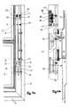
- the opening and closing of the slats 6 of the slat window can for example, manually, as shown in Fig. 4a and 4b.
- a handle 32 is arranged, which mechanically with an elongated bracket 31 is connected.
- the slats 6 are closed, in the dashed lines
- Position of the handle 32 the slats 6 are in the maximum open Status.
- the handle 32 can be any between these two positions Take position.
- the elongated bracket 31 corresponds to his Extension of the bracket 24, which is known to be the mechanical connection between the bushing 22 attached to the push rod 21 and the shaft 18 the slat 6 forms.
- the bearing of the shaft 18 the lamella 6 consists of a lower bearing shell 28, which is with her Projection 30 is in the recess 19 and against the two lugs 20th is pressed by means of two screws 47 (see FIG. 2a), and from one upper bearing shell 29, which is screwed to the lower bearing shell 29 becomes.
- the lamella connection 33 With the shaft 18, the lamella connection 33 is firmly connected, which in engages the slat frame 8 and in this way a firm connection present between the shaft 18 and the lamella 6.
- the one not shown angular cover 11 (FIG. 2) is in the region of the handle 32 with a appropriate recess.
- a manual actuation of the slats 6 is also a electromotive movement of the slats possible (Fig. 5a and 5b).
- Push rod 21 moves in the axial direction by using the bevel gear 36
- a threaded rod 37 is mechanically connected, which is in a Threaded sleeve 38 moves.
- a coupling part 39 is provided with the threaded sleeve 38 on the one hand articulated, which on the other hand articulated on the Push rod 21 is connected.
- the two switching devices 40 have the Task to interrupt the power supply to the electric motor 35 when the Push rod 21 one of its two end positions (slats 6 closed or opened to the maximum).
- the control of the electric motor 35 can for example via two buttons (open, close).
- electric motor 35 can also be operated by an electronic control device are controlled, sensors being connected to the same can, which in automatic operation of the louvre window Dependence on time, on temperature, on light, on the Arrange weather, etc.
- the electronic, not shown Control device can, for example, also within the Outer frame 1 (Fig. 1) can be accommodated in a suitable place.
Landscapes
- Engineering & Computer Science (AREA)
- Civil Engineering (AREA)
- Structural Engineering (AREA)
- Specific Sealing Or Ventilating Devices For Doors And Windows (AREA)
- Power-Operated Mechanisms For Wings (AREA)
- Wing Frames And Configurations (AREA)
- Glass Compositions (AREA)
Applications Claiming Priority (4)
| Application Number | Priority Date | Filing Date | Title |
|---|---|---|---|
| DE29920788U DE29920788U1 (de) | 1999-11-16 | 1999-11-16 | Profilintegrierter Antrieb zum Verstellen von Lamellenfenstern |
| DE29920788U | 1999-11-16 | ||
| DE20005330U DE20005330U1 (de) | 2000-03-22 | 2000-03-22 | Lamellenfenster |
| DE20005330U | 2000-03-22 |
Publications (3)
| Publication Number | Publication Date |
|---|---|
| EP1101896A2 true EP1101896A2 (fr) | 2001-05-23 |
| EP1101896A3 EP1101896A3 (fr) | 2003-05-28 |
| EP1101896B1 EP1101896B1 (fr) | 2006-04-26 |
Family
ID=26056168
Family Applications (1)
| Application Number | Title | Priority Date | Filing Date |
|---|---|---|---|
| EP00124915A Expired - Lifetime EP1101896B1 (fr) | 1999-11-16 | 2000-11-15 | Fenêtre à lamelles |
Country Status (4)
| Country | Link |
|---|---|
| EP (1) | EP1101896B1 (fr) |
| AT (1) | ATE324510T1 (fr) |
| CZ (1) | CZ297898B6 (fr) |
| DE (1) | DE50012640D1 (fr) |
Cited By (1)
| Publication number | Priority date | Publication date | Assignee | Title |
|---|---|---|---|---|
| DE102011054697A1 (de) | 2011-10-21 | 2013-04-25 | Glasbau Hahn Gmbh | Lamellenfenster mit einem elektromotorischen antrieb |
Citations (1)
| Publication number | Priority date | Publication date | Assignee | Title |
|---|---|---|---|---|
| DE4030627A1 (de) | 1990-09-27 | 1992-04-02 | Goetz Maria Theresia | Lamellenfenster |
Family Cites Families (3)
| Publication number | Priority date | Publication date | Assignee | Title |
|---|---|---|---|---|
| ATE25536T1 (de) * | 1983-03-10 | 1987-03-15 | Futura Aluminium Systems | Metallischer laden hergestellt aus zusammensetzbaren elementen. |
| US5907926A (en) * | 1997-10-16 | 1999-06-01 | Sosa Architectural Metal Corporation | Operating assembly for jalousie window |
| DE10007965A1 (de) * | 2000-02-22 | 2001-08-23 | Thomas Fieger | Lamellenfenster |
-
2000
- 2000-11-15 DE DE50012640T patent/DE50012640D1/de not_active Expired - Lifetime
- 2000-11-15 CZ CZ20004255A patent/CZ297898B6/cs not_active IP Right Cessation
- 2000-11-15 AT AT00124915T patent/ATE324510T1/de active
- 2000-11-15 EP EP00124915A patent/EP1101896B1/fr not_active Expired - Lifetime
Patent Citations (1)
| Publication number | Priority date | Publication date | Assignee | Title |
|---|---|---|---|---|
| DE4030627A1 (de) | 1990-09-27 | 1992-04-02 | Goetz Maria Theresia | Lamellenfenster |
Cited By (2)
| Publication number | Priority date | Publication date | Assignee | Title |
|---|---|---|---|---|
| DE102011054697A1 (de) | 2011-10-21 | 2013-04-25 | Glasbau Hahn Gmbh | Lamellenfenster mit einem elektromotorischen antrieb |
| DE102011054697B4 (de) | 2011-10-21 | 2025-01-30 | Glasbau Hahn Gmbh | Lamellenfenster mit einem elektromotorischen antrieb |
Also Published As
| Publication number | Publication date |
|---|---|
| CZ297898B6 (cs) | 2007-04-25 |
| EP1101896A3 (fr) | 2003-05-28 |
| ATE324510T1 (de) | 2006-05-15 |
| DE50012640D1 (de) | 2006-06-01 |
| EP1101896B1 (fr) | 2006-04-26 |
| CZ20004255A3 (cs) | 2001-07-11 |
Similar Documents
| Publication | Publication Date | Title |
|---|---|---|
| DE2806117C2 (de) | Elektrisch betätigbarer Fensterantrieb, insbesondere für Kraftfahrzeuge | |
| DE69804557T2 (de) | Betätigungsvorrichtung für eine Jalousie o.dgl. innerhalb einer Doppelverglasung | |
| EP1643065A2 (fr) | Dispositif d'entraînement d'une porte | |
| DE19645802C1 (de) | Lamellenfenster für im wesentlichen senkrechte Fassaden | |
| DE19912717A1 (de) | Fenster oder Tür | |
| DE602004002853T2 (de) | Automatisierte sonnenschutzeinrichtung | |
| DE4407276A1 (de) | Ausstellvorrichtung für einen Flügel eines Fensters, Lüftungsklappe, Lichtkuppel, Tür oder dergleichen sowie Antrieb zur Bewegung zweier Bauteile relativ zueinander | |
| DE3136854C2 (de) | Hebedach | |
| DE3600211C1 (de) | Fenster- und Tuerbeschlag | |
| DE4115054A1 (de) | Einrichtung zur belueftung von fenster oder tueren mit beweglichem fluegel aufweisenden raeumen in gebaeuden | |
| DE69910465T2 (de) | Betätigungsvorrichtung für Tür- oder Fensterkonstruktionen mit schwenkbaren Flügelelementen | |
| EP1128018B1 (fr) | Fenêtre à lamelles | |
| EP3702555B1 (fr) | Agencement de porte ou de fenêtre doté d'une unité d'entraînement dans le bâti dormant | |
| EP1101896B1 (fr) | Fenêtre à lamelles | |
| DE69822259T2 (de) | Fensterbetätigungsvorrichtung für ein Kraftfahrzeug, insbesondere für ein Cabriolet-Fahrzeug | |
| EP1098417A1 (fr) | Actionnement électrique | |
| EP0054213B1 (fr) | Dispositif de déflecteur pour fenêtres ou portes comprenant un boîtier pour le compas, réglable dans l'axe longitudinal de la traverse supérieure du cadre | |
| EP0851083B1 (fr) | Fenêtre coulissant verticalement | |
| EP0386535B1 (fr) | Mécanisme d'entraînement pour déplacer un élément | |
| DE4401056C1 (de) | Rolladen für ein Dachfenster | |
| DE3000579A1 (de) | Oberlichtoeffner | |
| DE602005002067T2 (de) | Tür- oder Fensterstruktur aus einem Metallprofilstab | |
| DE69410796T2 (de) | Fenster nach jalousie-art | |
| DE19701799C2 (de) | Ausstellmechanismus | |
| DE20005330U1 (de) | Lamellenfenster |
Legal Events
| Date | Code | Title | Description |
|---|---|---|---|
| PUAI | Public reference made under article 153(3) epc to a published international application that has entered the european phase |
Free format text: ORIGINAL CODE: 0009012 |
|
| AK | Designated contracting states |
Kind code of ref document: A2 Designated state(s): AT BE CH CY DE DK ES FI FR GB GR IE IT LI LU MC NL PT SE TR |
|
| AX | Request for extension of the european patent |
Free format text: AL;LT;LV;MK;RO;SI |
|
| PUAL | Search report despatched |
Free format text: ORIGINAL CODE: 0009013 |
|
| AK | Designated contracting states |
Designated state(s): AT BE CH CY DE DK ES FI FR GB GR IE IT LI LU MC NL PT SE TR |
|
| AX | Request for extension of the european patent |
Extension state: AL LT LV MK RO SI |
|
| 17P | Request for examination filed |
Effective date: 20031121 |
|
| AKX | Designation fees paid |
Designated state(s): AT CH FR LI |
|
| RBV | Designated contracting states (corrected) |
Designated state(s): AT CH DE LI |
|
| REG | Reference to a national code |
Ref country code: DE Ref legal event code: 8566 |
|
| GRAP | Despatch of communication of intention to grant a patent |
Free format text: ORIGINAL CODE: EPIDOSNIGR1 |
|
| GRAS | Grant fee paid |
Free format text: ORIGINAL CODE: EPIDOSNIGR3 |
|
| GRAA | (expected) grant |
Free format text: ORIGINAL CODE: 0009210 |
|
| AK | Designated contracting states |
Kind code of ref document: B1 Designated state(s): AT CH DE LI |
|
| REF | Corresponds to: |
Ref document number: 50012640 Country of ref document: DE Date of ref document: 20060601 Kind code of ref document: P |
|
| REG | Reference to a national code |
Ref country code: CH Ref legal event code: NV Representative=s name: E. BLUM & CO. PATENTANWAELTE |
|
| PLBE | No opposition filed within time limit |
Free format text: ORIGINAL CODE: 0009261 |
|
| STAA | Information on the status of an ep patent application or granted ep patent |
Free format text: STATUS: NO OPPOSITION FILED WITHIN TIME LIMIT |
|
| 26N | No opposition filed |
Effective date: 20070129 |
|
| REG | Reference to a national code |
Ref country code: CH Ref legal event code: PFA Owner name: GLASBAU HAHN GMBH & CO. KG Free format text: GLASBAU HAHN GMBH & CO. KG#HANAUER LANDSTRASSE 211#D-60314 FRANKFURT (DE) -TRANSFER TO- GLASBAU HAHN GMBH & CO. KG#HANAUER LANDSTRASSE 211#D-60314 FRANKFURT (DE) |
|
| PGFP | Annual fee paid to national office [announced via postgrant information from national office to epo] |
Ref country code: AT Payment date: 20101119 Year of fee payment: 11 |
|
| PGFP | Annual fee paid to national office [announced via postgrant information from national office to epo] |
Ref country code: CH Payment date: 20101124 Year of fee payment: 11 Ref country code: DE Payment date: 20101129 Year of fee payment: 11 |
|
| REG | Reference to a national code |
Ref country code: CH Ref legal event code: PL |
|
| PG25 | Lapsed in a contracting state [announced via postgrant information from national office to epo] |
Ref country code: CH Free format text: LAPSE BECAUSE OF NON-PAYMENT OF DUE FEES Effective date: 20111130 Ref country code: LI Free format text: LAPSE BECAUSE OF NON-PAYMENT OF DUE FEES Effective date: 20111130 |
|
| REG | Reference to a national code |
Ref country code: DE Ref legal event code: R119 Ref document number: 50012640 Country of ref document: DE Effective date: 20120601 |
|
| REG | Reference to a national code |
Ref country code: AT Ref legal event code: MM01 Ref document number: 324510 Country of ref document: AT Kind code of ref document: T Effective date: 20111115 |
|
| PG25 | Lapsed in a contracting state [announced via postgrant information from national office to epo] |
Ref country code: AT Free format text: LAPSE BECAUSE OF NON-PAYMENT OF DUE FEES Effective date: 20111115 |
|
| PG25 | Lapsed in a contracting state [announced via postgrant information from national office to epo] |
Ref country code: DE Free format text: LAPSE BECAUSE OF NON-PAYMENT OF DUE FEES Effective date: 20120601 |