EP1101921A2 - Zylinderkopf für eine Mehrzylinderreihenbrennkraftmaschine mit einem Sekundärluftsystem - Google Patents
Zylinderkopf für eine Mehrzylinderreihenbrennkraftmaschine mit einem Sekundärluftsystem Download PDFInfo
- Publication number
- EP1101921A2 EP1101921A2 EP00122747A EP00122747A EP1101921A2 EP 1101921 A2 EP1101921 A2 EP 1101921A2 EP 00122747 A EP00122747 A EP 00122747A EP 00122747 A EP00122747 A EP 00122747A EP 1101921 A2 EP1101921 A2 EP 1101921A2
- Authority
- EP
- European Patent Office
- Prior art keywords
- channels
- channel
- cylinder
- exhaust
- sub
- Prior art date
- Legal status (The legal status is an assumption and is not a legal conclusion. Google has not performed a legal analysis and makes no representation as to the accuracy of the status listed.)
- Granted
Links
Images


Classifications
-
- F—MECHANICAL ENGINEERING; LIGHTING; HEATING; WEAPONS; BLASTING
- F02—COMBUSTION ENGINES; HOT-GAS OR COMBUSTION-PRODUCT ENGINE PLANTS
- F02F—CYLINDERS, PISTONS OR CASINGS, FOR COMBUSTION ENGINES; ARRANGEMENTS OF SEALINGS IN COMBUSTION ENGINES
- F02F1/00—Cylinders; Cylinder heads
- F02F1/24—Cylinder heads
- F02F1/26—Cylinder heads having cooling means
- F02F1/36—Cylinder heads having cooling means for liquid cooling
- F02F1/38—Cylinder heads having cooling means for liquid cooling the cylinder heads being of overhead valve type
-
- F—MECHANICAL ENGINEERING; LIGHTING; HEATING; WEAPONS; BLASTING
- F01—MACHINES OR ENGINES IN GENERAL; ENGINE PLANTS IN GENERAL; STEAM ENGINES
- F01N—GAS-FLOW SILENCERS OR EXHAUST APPARATUS FOR MACHINES OR ENGINES IN GENERAL; GAS-FLOW SILENCERS OR EXHAUST APPARATUS FOR INTERNAL-COMBUSTION ENGINES
- F01N3/00—Exhaust or silencing apparatus having means for purifying, rendering innocuous, or otherwise treating exhaust
- F01N3/08—Exhaust or silencing apparatus having means for purifying, rendering innocuous, or otherwise treating exhaust for rendering innocuous
- F01N3/10—Exhaust or silencing apparatus having means for purifying, rendering innocuous, or otherwise treating exhaust for rendering innocuous by thermal or catalytic conversion of noxious components of exhaust
- F01N3/24—Exhaust or silencing apparatus having means for purifying, rendering innocuous, or otherwise treating exhaust for rendering innocuous by thermal or catalytic conversion of noxious components of exhaust characterised by constructional aspects of converting apparatus
- F01N3/30—Arrangements for supply of additional air
- F01N3/34—Arrangements for supply of additional air using air conduits or jet air pumps, e.g. near the engine exhaust port
-
- F—MECHANICAL ENGINEERING; LIGHTING; HEATING; WEAPONS; BLASTING
- F02—COMBUSTION ENGINES; HOT-GAS OR COMBUSTION-PRODUCT ENGINE PLANTS
- F02B—INTERNAL-COMBUSTION PISTON ENGINES; COMBUSTION ENGINES IN GENERAL
- F02B75/00—Other engines
- F02B75/16—Engines characterised by number of cylinders, e.g. single-cylinder engines
- F02B75/18—Multi-cylinder engines
- F02B2075/1804—Number of cylinders
- F02B2075/1816—Number of cylinders four
-
- F—MECHANICAL ENGINEERING; LIGHTING; HEATING; WEAPONS; BLASTING
- F02—COMBUSTION ENGINES; HOT-GAS OR COMBUSTION-PRODUCT ENGINE PLANTS
- F02B—INTERNAL-COMBUSTION PISTON ENGINES; COMBUSTION ENGINES IN GENERAL
- F02B75/00—Other engines
- F02B75/16—Engines characterised by number of cylinders, e.g. single-cylinder engines
- F02B75/18—Multi-cylinder engines
- F02B2075/1804—Number of cylinders
- F02B2075/1824—Number of cylinders six
-
- F—MECHANICAL ENGINEERING; LIGHTING; HEATING; WEAPONS; BLASTING
- F02—COMBUSTION ENGINES; HOT-GAS OR COMBUSTION-PRODUCT ENGINE PLANTS
- F02B—INTERNAL-COMBUSTION PISTON ENGINES; COMBUSTION ENGINES IN GENERAL
- F02B75/00—Other engines
- F02B75/16—Engines characterised by number of cylinders, e.g. single-cylinder engines
- F02B75/18—Multi-cylinder engines
- F02B75/20—Multi-cylinder engines with cylinders all in one line
-
- Y—GENERAL TAGGING OF NEW TECHNOLOGICAL DEVELOPMENTS; GENERAL TAGGING OF CROSS-SECTIONAL TECHNOLOGIES SPANNING OVER SEVERAL SECTIONS OF THE IPC; TECHNICAL SUBJECTS COVERED BY FORMER USPC CROSS-REFERENCE ART COLLECTIONS [XRACs] AND DIGESTS
- Y02—TECHNOLOGIES OR APPLICATIONS FOR MITIGATION OR ADAPTATION AGAINST CLIMATE CHANGE
- Y02T—CLIMATE CHANGE MITIGATION TECHNOLOGIES RELATED TO TRANSPORTATION
- Y02T10/00—Road transport of goods or passengers
- Y02T10/10—Internal combustion engine [ICE] based vehicles
- Y02T10/12—Improving ICE efficiencies
Definitions
- the invention relates to a cylinder head for a multi-cylinder in-line combustion engine having a secondary air supply system, comprising a longitudinal channel provided with a secondary air supply by a valve, from which longitudinal channel lead stub-lines to each cylinders' exhaust channels, which flow through the cylinder head into a flange mounted exhaust gas manifold, where at least two separately carried exhaust gas manifolds, as regards the gas flow, are provided.
- the exhaust channel is connected to at least two cylinders.
- the technical field is shown in DE 44 45 971 and in particular in DE 195 31 875 C1.
- the later document shows a combustion engine cylinder head with the known features of the pre-characterizing portion of claim 1. Basically it shows a cylinder head of the kind set forth in which secondary air for treatment of the exaust gas is supplied to the aligned cylinders of the combustion engine in a particularly manner by flow through a longitudinal channel running through the cylinder head. With such a longitudinal channel costly arrangements for the distribution of the secondary air supply outside of the cylinder head can be avoided.
- a secondary air pump feeds pipes, via a valve, the desired secondary air stream to one of the cylinder exhaust channels leading to the secondary air supply each of the pipes being provided with an independant individual valve. In this way an exact control of the secondary air supply is possible, i. e. in each exhaust channel the secondary air flow will only occur, if combustion engine exhaust gas also flows in these channels.
- a secondary air system is desired in which the construction is essentially as simple as in the generic construction of DE 195 31 875 C1, but contains no inconvenient or undesireable connections. In particular, there should be no expense incurred in arranging the secondary air pipes outside of the cylinder head.
- a cylinder head for an in-line combustion engine in which these requirements are made forms the basis for the present invention.
- the solution to the problem is characterized in that the longitudinal passage is divided into a number of sub-channels, the number being the same as the number of exhaust manifolds, such that a gas path from the said valve to the respective seperate sub-channels of the individual exhaust gas manifolds is such that each sub-channel is joined by way of the exhaust gas manifold to supply the cylinder exhaust gas channel with secondary air.
- the present invention is based on the realisation that with regard to the gas paths of the respective seperate exhaust gas manifolds, usually, at least two are provided.
- the manifolds are normally secured to the side of the cylinder head and are combined with the cylinder exhaust channels of the respective cylinders.
- this is relatively harmless, as the exhaust channels of the different cylinders will be normally be connencted together to an exhaust manifold, dependent upon the ignition sequence of the combustion engine cylinder.
- the first and forth cylinders are brought together in a first exhaust manifold and the second and the third cylinders in a second exhaust manifold.
- the exhaust channels of cylinders no. 1 to 3 may be combined in a first exhaust manifold and the exhaust channels of cylinders no. 4 to 6 are combined in a second exhaust manifold.
- the longitudinal channel serving the secondary air supply should be divided into as many sub-channel as are provided exhaust gas manifolds, whereby each sub-chamber is associated with an exhaust gas manifold.
- the associated exhaust gas channel then provides each with the secondary air distribution serving the sub-channel just like a connection.
- a similar connection is present through the exhaust gas manifold, such that through this sub-channel no (additional) detrimental effect is provided.
- this is achieved by a relatively simple construction, since the division of the longitudinal channels in the cylinder head of an in-line engine can simply be realized, for example if this division is by way of insertion of a suitably shaped insertion element, positioned in the longitudinal channel.
- the inserted element may be formed as a pipe spaced and separated along its length from the wall of the longitudinal channel such that the first sub-channel is constructed through the pipe innerspace and the second sub-channel is constructed through the space between the tube wall and the wall of the longitudinal channel.
- FIG. 1 shows a longitudinal cross section through a cylinder head of a four cylinder in-line combustion engine
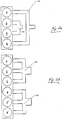
- Fig. 2a and 2b show a somewhat simplified exhaust manifold of a cylinder head of a four cylinder and six cylinder combustion engine
- Fig. 3 shows a perspective view of a preferred insertion element in the form of a tube.
- a cylinder head of a 4 cylinder (Fig. 1, 2a) or 6 cylinder (Fig. 2b) piston in-line combustion engine is shown at reference no. 10, in which individual cylinders are arranged, reference nos. 1 to 4 or 1 to 6.
- a combustable mixture is ignited, after which the exhaust gas is introduced into the cylinder exhaust channel 11.
- the exhaust channels of several cylinders are brought together in exhaust manifolds 12a, 12b, which are mounted to one side of the cylinder head 10.
- the exhaust channels of cylinders 1 and 4 are brought together in the first exhaust manifold 12a and those of cylinders 2 and 3 in a second exhaust manifold 12b.
- Fig. 1 shows that cylinders 1 to 4 are each provided with two exhaust channels 11. However, this is not essential for the present invention. It is more important, that in the cylinder head 10 there runs a longitudinal channel 13 by which a secondary air supply is introduced into the exhaust channels for subsequent treatment. From longitudinal channel 13 branch off so called stub lines 14 which likewise operate inside of the cylinder head 10, and flow into respective exhaust channels 11.
- the desired secondary air stream is fed through a supply line 15 to cylinder head 10 and fed over (here two) parrallel tapped channels 16a, 16b into the longitudinal channel 13.
- a secondary air pump (not shown) by way of supply line 15 introduces secondary air flow through tapped channels 16a, 16b into the longitudinal channel 13, while by closing valve 17 the connection between the supply line 15 and the tapped channels 16a, 16b is broken.
- valve 17 is constructed and arranged so that the valve head 17a of this valve 17 has a closed position which interrupts the connection existing between the tapped channels 16a, 16b when the valve head is in an open position.
- This situation occurs as described such that the tapped channels 16a, 16b of the valve 17 at least as far as the gas flow is concerned are isolated from one another (that is in relation to the down-stream secondary air flow).
- insert element 18 comprises a pipe which is spaced and separated along its length from the wall 19 of the longitudinal channel 13 which will be given the reference no. 18 in the following, and in Fig. 3 this element is shown again but from a different perspective.
- This pipe is arranged in such a way to be concentic within longitudinal channel 13, such that the first sub-channel 13a extends substantially through an innerspace of the pipe and the second sub-channel 13b through at least a section of the space between the pipe wall (not shown with a separate reference no.) and the wall 19 of the longitudinal channel 13.
- the pipe extends essentially the whole length of the longitudinal channel 13.
- respective shoulders 201 and 20r extend from pipe 18 to the wall 19 of the longitudinal channel 13.
- the second sub-channel 13b is disposed within the section of the longitudinal channel 13 between the pair of shoulders 201 and 20r so as to be between the pipe wall and the wall 19.
- the first part of sub-channel 13a comprising the section of the longitudinal channel 13 lying on the right hand side of the right shoulder 20r and the second part comprising the section of the longitudinal channel 13 lying on the left hand side of the left shoulder 201 are connected by way of the pipe innerspace, i. e. adjoining a pipe innerspace through that region of the longitudinal channel 13 which does not comprise the second sub-channel 13b.
- valve 17 there is a first flow from valve 17 by way of connecting tapped channels 16a in the region of the first cylinder 1 in the longitudinal channel 13 (and thus in sub-channel 13a) while a second flow exists from valve 17 and associated tapped channel 16b in the region between the two shoulders 201 and 20r in the longitudinal channel 13 and thus in the second sub-channel 13b.
- pipe 18 is provided at both its end regions, i. e. respectively in the region of the first cylinder 1 and the forth cylinder 4, with at least one exchange opening 21, i. e. in these said end regions the tube wall is provided with at least one exchange opening 21 which makes possible a gas exchange from the pipe innerspace in the space between the pipe-wall and the wall 19 of the longitudinal channel 13 (or vice versa).
- the secondary air supply induced over the first tapped channel 16a reaches the right collar 20r located in the region of the longitudinal channel 13, i. e. in the region of the longitudinal channel 13 associated with the first cylinder 1 and likewise in the first part channel 13a.
- a portion of the secondary air flow extends over the stub lines 14 provided in the exhaust channel of the first cylinder 1. It can further be seen that a part of the secondary air flows over the (right hand side, here both) exchange openings 21 into the pipe innerspace and flows to the oppositely disposed pipe end, i. e. to the left hand side of the section of pipe 18 associated with the forth cylinder 4.
- the secondary air flow portion exchanges at the provided (left hand side, here both) exchange openings 21 to the left hand side of the left collar 211 of the longitudinal channel 13. This portion of the secondary air flow is always in the first sub-channel 13a. From here the secondary air flow portion flows over the disposed stub line 14 into the exhaust channels 11 associated with the forth cyllinder 4.
- sub-channel 13a a secondary air flow is delivered to cylinders 1 and 4, with regard to the gas flow downstream of valve(s) 17 absolutely separated from sub-channel 13b through which secondary air flow to cylinders 2 and 3 is provided.
- valve(s) 17 By closing valve 17, if the valve plate 17a covers a dividing web, shown at reference no. 22 between the two tapped channels 16a, 16b, and while in sub-channels 13a, 13b naturally exhaust gas from the sequential cylinders is located, no exhaust gas from the sub-channel 13a can reach sub-channel 13b (and vice versa).
Landscapes
- Engineering & Computer Science (AREA)
- Chemical & Material Sciences (AREA)
- Combustion & Propulsion (AREA)
- Mechanical Engineering (AREA)
- General Engineering & Computer Science (AREA)
- Chemical Kinetics & Catalysis (AREA)
- Health & Medical Sciences (AREA)
- Toxicology (AREA)
- Exhaust Gas After Treatment (AREA)
- Cylinder Crankcases Of Internal Combustion Engines (AREA)
Applications Claiming Priority (2)
| Application Number | Priority Date | Filing Date | Title |
|---|---|---|---|
| GB9927087 | 1999-11-17 | ||
| GBGB9927087.8A GB9927087D0 (en) | 1999-11-17 | 1999-11-17 | Cylinder head for a multi-cylinder in-line combustion engine having secodary air supply system |
Publications (3)
| Publication Number | Publication Date |
|---|---|
| EP1101921A2 true EP1101921A2 (de) | 2001-05-23 |
| EP1101921A3 EP1101921A3 (de) | 2002-05-02 |
| EP1101921B1 EP1101921B1 (de) | 2008-12-17 |
Family
ID=10864610
Family Applications (1)
| Application Number | Title | Priority Date | Filing Date |
|---|---|---|---|
| EP00122747A Expired - Lifetime EP1101921B1 (de) | 1999-11-17 | 2000-10-19 | Zylinderkopf für eine Mehrzylinderreihenbrennkraftmaschine mit einem Sekundärluftsystem |
Country Status (3)
| Country | Link |
|---|---|
| EP (1) | EP1101921B1 (de) |
| DE (1) | DE60041112D1 (de) |
| GB (1) | GB9927087D0 (de) |
Cited By (3)
| Publication number | Priority date | Publication date | Assignee | Title |
|---|---|---|---|---|
| EP1296031A3 (de) * | 2001-09-22 | 2003-09-03 | Bayerische Motoren Werke Aktiengesellschaft | Brennkraftmaschine mit Abgasanlage und Sekundärluftzuführung |
| US20140230772A1 (en) * | 2013-02-15 | 2014-08-21 | GM Global Technology Operations LLC | Dual path sair for dual plane integrated exhaust manifolds |
| FR3078365A1 (fr) * | 2018-02-28 | 2019-08-30 | Renault S.A.S | Dispositif de controle et de gestion de l'injection d'air a l'echappement |
Citations (2)
| Publication number | Priority date | Publication date | Assignee | Title |
|---|---|---|---|---|
| DE4445971A1 (de) | 1994-12-22 | 1996-06-27 | Bosch Gmbh Robert | Verfahren zur Steuerung der Zufuhr von Sekundärluft in Brennkraftmaschinen und Vorrichtung |
| DE19531875C1 (de) | 1995-08-30 | 1996-09-19 | Daimler Benz Ag | Zylinderkopf für eine flüssigkeitsgekühlte, mehrzylindrische Brennkraftmaschine |
Family Cites Families (6)
| Publication number | Priority date | Publication date | Assignee | Title |
|---|---|---|---|---|
| US3690105A (en) * | 1971-04-08 | 1972-09-12 | Bonnie G Faulkner | After burning device for internal combustion engines |
| DE4106499C1 (en) * | 1991-03-01 | 1992-03-19 | Bayerische Motoren Werke Ag, 8000 Muenchen, De | IC engine with exhaust gas analysis - draws of gas through line used for air injection |
| FR2723615B1 (fr) * | 1994-08-12 | 1996-09-27 | Peugeot | Procede de refroidissement des gaz d'echappement d'un moteur a combustion interne muni d'un collecteur d'echappement a double paroi et dispositif pour la mise en oeuvre de ce procede |
| GB2292975A (en) * | 1994-09-10 | 1996-03-13 | Ford Motor Co | I.c. engine cylinder head exhaust recirculation |
| DE4445490A1 (de) * | 1994-12-20 | 1996-06-27 | Audi Ag | Vorrichtung zur Abgasentgiftung an einer Brennkraftmaschine |
| DE19635535C2 (de) * | 1996-09-02 | 1998-07-23 | Daimler Benz Ag | Gegossener Zylinderkopf einer mehrzylindrigen Brennkraftmaschine |
-
1999
- 1999-11-17 GB GBGB9927087.8A patent/GB9927087D0/en not_active Ceased
-
2000
- 2000-10-19 EP EP00122747A patent/EP1101921B1/de not_active Expired - Lifetime
- 2000-10-19 DE DE60041112T patent/DE60041112D1/de not_active Expired - Lifetime
Patent Citations (2)
| Publication number | Priority date | Publication date | Assignee | Title |
|---|---|---|---|---|
| DE4445971A1 (de) | 1994-12-22 | 1996-06-27 | Bosch Gmbh Robert | Verfahren zur Steuerung der Zufuhr von Sekundärluft in Brennkraftmaschinen und Vorrichtung |
| DE19531875C1 (de) | 1995-08-30 | 1996-09-19 | Daimler Benz Ag | Zylinderkopf für eine flüssigkeitsgekühlte, mehrzylindrische Brennkraftmaschine |
Cited By (5)
| Publication number | Priority date | Publication date | Assignee | Title |
|---|---|---|---|---|
| EP1296031A3 (de) * | 2001-09-22 | 2003-09-03 | Bayerische Motoren Werke Aktiengesellschaft | Brennkraftmaschine mit Abgasanlage und Sekundärluftzuführung |
| US20140230772A1 (en) * | 2013-02-15 | 2014-08-21 | GM Global Technology Operations LLC | Dual path sair for dual plane integrated exhaust manifolds |
| US8850804B2 (en) * | 2013-02-15 | 2014-10-07 | GM Global Technology Operations LLC | Dual path SAIR for dual plane integrated exhaust manifolds |
| DE102014101595B4 (de) | 2013-02-15 | 2023-02-02 | GM Global Technology Operations LLC (n. d. Ges. d. Staates Delaware) | Sekundärluft-einblassystem für einen verbrennungsmotor |
| FR3078365A1 (fr) * | 2018-02-28 | 2019-08-30 | Renault S.A.S | Dispositif de controle et de gestion de l'injection d'air a l'echappement |
Also Published As
| Publication number | Publication date |
|---|---|
| EP1101921A3 (de) | 2002-05-02 |
| EP1101921B1 (de) | 2008-12-17 |
| GB9927087D0 (en) | 2000-01-12 |
| DE60041112D1 (de) | 2009-01-29 |
Similar Documents
| Publication | Publication Date | Title |
|---|---|---|
| US4517951A (en) | Intake manifold apparatus in multi-cylinder engine | |
| JP2635873B2 (ja) | 内燃機関用の吸気マニホルド | |
| EP1469171B1 (de) | Brennkraftmaschine mit Entlüftungsvorrichtung | |
| US20100126153A1 (en) | Internal combustion engine | |
| US5014654A (en) | Intake manifold for internal combustion engine | |
| US4640256A (en) | Internal combustion engine exhaust gas recycling arrangement | |
| US10107229B2 (en) | Cylinder head and internal combustion engine | |
| US4727829A (en) | Intake system for internal combustion engine | |
| EP1101921B1 (de) | Zylinderkopf für eine Mehrzylinderreihenbrennkraftmaschine mit einem Sekundärluftsystem | |
| EP1103701A3 (de) | Katalysatoranordnung im Abgassystem einer mehrzylindrigen Brennkraftmaschine | |
| KR950014567A (ko) | 내연기관의 흡기장치 | |
| EP0523029B1 (de) | Vorrichtung an Ansaugsystemen für Brennkraftmaschinen | |
| GB2158877A (en) | An i c engine valve seat insert cooling arrangement | |
| EP1291500A3 (de) | Abgasanlage für mehrzylindrige Verbrennungsmotoren | |
| DE3367652D1 (en) | Covernor air inlet arrangement for internal-combustion engines, particularly multicylinder fuel injection internal-combustion engines | |
| CN1316148C (zh) | 曲轴箱强制通风系统 | |
| JPH0514085B2 (de) | ||
| JP4092125B2 (ja) | エギゾーストマニホールド | |
| JPH10122036A (ja) | 内燃機関の排ガス再循環装置 | |
| US6622687B2 (en) | Intake apparatus of multi-cylinder internal combustion engine | |
| JPH0734169Y2 (ja) | 内燃機関の排気管装置 | |
| EP2369161B1 (de) | Abgasabströmanordnung | |
| JP7540252B2 (ja) | インテークマニホールド | |
| KR100610852B1 (ko) | 자동차의 배기 매니폴드 | |
| KR800000514B1 (ko) | 다기통 내연기관의 배기정화장치 |
Legal Events
| Date | Code | Title | Description |
|---|---|---|---|
| PUAI | Public reference made under article 153(3) epc to a published international application that has entered the european phase |
Free format text: ORIGINAL CODE: 0009012 |
|
| AK | Designated contracting states |
Kind code of ref document: A2 Designated state(s): AT BE CH CY DE DK ES FI FR GB GR IE IT LI LU MC NL PT SE Kind code of ref document: A2 Designated state(s): DE FR GB IT |
|
| AX | Request for extension of the european patent |
Free format text: AL;LT;LV;MK;RO;SI |
|
| PUAL | Search report despatched |
Free format text: ORIGINAL CODE: 0009013 |
|
| AK | Designated contracting states |
Kind code of ref document: A3 Designated state(s): AT BE CH CY DE DK ES FI FR GB GR IE IT LI LU MC NL PT SE |
|
| AX | Request for extension of the european patent |
Free format text: AL;LT;LV;MK;RO;SI |
|
| 17P | Request for examination filed |
Effective date: 20020517 |
|
| AKX | Designation fees paid |
Free format text: DE FR GB IT |
|
| 17Q | First examination report despatched |
Effective date: 20070621 |
|
| GRAP | Despatch of communication of intention to grant a patent |
Free format text: ORIGINAL CODE: EPIDOSNIGR1 |
|
| GRAS | Grant fee paid |
Free format text: ORIGINAL CODE: EPIDOSNIGR3 |
|
| GRAA | (expected) grant |
Free format text: ORIGINAL CODE: 0009210 |
|
| AK | Designated contracting states |
Kind code of ref document: B1 Designated state(s): DE FR GB IT |
|
| REG | Reference to a national code |
Ref country code: GB Ref legal event code: FG4D |
|
| REF | Corresponds to: |
Ref document number: 60041112 Country of ref document: DE Date of ref document: 20090129 Kind code of ref document: P |
|
| PLBE | No opposition filed within time limit |
Free format text: ORIGINAL CODE: 0009261 |
|
| STAA | Information on the status of an ep patent application or granted ep patent |
Free format text: STATUS: NO OPPOSITION FILED WITHIN TIME LIMIT |
|
| 26N | No opposition filed |
Effective date: 20090918 |
|
| REG | Reference to a national code |
Ref country code: FR Ref legal event code: PLFP Year of fee payment: 16 |
|
| REG | Reference to a national code |
Ref country code: FR Ref legal event code: PLFP Year of fee payment: 17 |
|
| PGFP | Annual fee paid to national office [announced via postgrant information from national office to epo] |
Ref country code: DE Payment date: 20161021 Year of fee payment: 17 Ref country code: FR Payment date: 20161025 Year of fee payment: 17 Ref country code: GB Payment date: 20161025 Year of fee payment: 17 |
|
| PGFP | Annual fee paid to national office [announced via postgrant information from national office to epo] |
Ref country code: IT Payment date: 20161025 Year of fee payment: 17 |
|
| REG | Reference to a national code |
Ref country code: DE Ref legal event code: R119 Ref document number: 60041112 Country of ref document: DE |
|
| GBPC | Gb: european patent ceased through non-payment of renewal fee |
Effective date: 20171019 |
|
| REG | Reference to a national code |
Ref country code: FR Ref legal event code: ST Effective date: 20180629 |
|
| PG25 | Lapsed in a contracting state [announced via postgrant information from national office to epo] |
Ref country code: GB Free format text: LAPSE BECAUSE OF NON-PAYMENT OF DUE FEES Effective date: 20171019 Ref country code: DE Free format text: LAPSE BECAUSE OF NON-PAYMENT OF DUE FEES Effective date: 20180501 |
|
| PG25 | Lapsed in a contracting state [announced via postgrant information from national office to epo] |
Ref country code: FR Free format text: LAPSE BECAUSE OF NON-PAYMENT OF DUE FEES Effective date: 20171031 |
|
| PG25 | Lapsed in a contracting state [announced via postgrant information from national office to epo] |
Ref country code: IT Free format text: LAPSE BECAUSE OF NON-PAYMENT OF DUE FEES Effective date: 20171019 |