EP1102029A2 - Treibladung mit einer Mehrpunktanzündung - Google Patents
Treibladung mit einer Mehrpunktanzündung Download PDFInfo
- Publication number
- EP1102029A2 EP1102029A2 EP00123832A EP00123832A EP1102029A2 EP 1102029 A2 EP1102029 A2 EP 1102029A2 EP 00123832 A EP00123832 A EP 00123832A EP 00123832 A EP00123832 A EP 00123832A EP 1102029 A2 EP1102029 A2 EP 1102029A2
- Authority
- EP
- European Patent Office
- Prior art keywords
- igniters
- drive according
- igniter
- ignition
- performance drive
- Prior art date
- Legal status (The legal status is an assumption and is not a legal conclusion. Google has not performed a legal analysis and makes no representation as to the accuracy of the status listed.)
- Granted
Links
- 239000003380 propellant Substances 0.000 title claims description 28
- 238000000034 method Methods 0.000 claims abstract description 4
- 239000000843 powder Substances 0.000 claims description 25
- 238000010304 firing Methods 0.000 abstract description 4
- 239000002245 particle Substances 0.000 description 2
- 241001136792 Alle Species 0.000 description 1
- 241000209035 Ilex Species 0.000 description 1
- 230000002411 adverse Effects 0.000 description 1
- 238000010276 construction Methods 0.000 description 1
- 230000006378 damage Effects 0.000 description 1
- 230000007613 environmental effect Effects 0.000 description 1
- 239000003517 fume Substances 0.000 description 1
- 239000007789 gas Substances 0.000 description 1
- 230000001535 kindling effect Effects 0.000 description 1
- 238000005259 measurement Methods 0.000 description 1
- 239000002184 metal Substances 0.000 description 1
- 239000000203 mixture Substances 0.000 description 1
- 230000001960 triggered effect Effects 0.000 description 1
Images
Classifications
-
- F—MECHANICAL ENGINEERING; LIGHTING; HEATING; WEAPONS; BLASTING
- F41—WEAPONS
- F41A—FUNCTIONAL FEATURES OR DETAILS COMMON TO BOTH SMALLARMS AND ORDNANCE, e.g. CANNONS; MOUNTINGS FOR SMALLARMS OR ORDNANCE
- F41A19/00—Firing or trigger mechanisms; Cocking mechanisms
- F41A19/58—Electric firing mechanisms
-
- F—MECHANICAL ENGINEERING; LIGHTING; HEATING; WEAPONS; BLASTING
- F42—AMMUNITION; BLASTING
- F42B—EXPLOSIVE CHARGES, e.g. FOR BLASTING, FIREWORKS, AMMUNITION
- F42B35/00—Testing or checking of ammunition
-
- F—MECHANICAL ENGINEERING; LIGHTING; HEATING; WEAPONS; BLASTING
- F42—AMMUNITION; BLASTING
- F42B—EXPLOSIVE CHARGES, e.g. FOR BLASTING, FIREWORKS, AMMUNITION
- F42B5/00—Cartridge ammunition, e.g. separately-loaded propellant charges
- F42B5/02—Cartridges, i.e. cases with charge and missile
- F42B5/08—Cartridges, i.e. cases with charge and missile modified for electric ignition
Definitions
- the invention relates to a high-performance drive with arranged in a sleeve Propellant powder and a pyrotechnic lighter to ignite the Propellant powder, the lighter an ignition charge and optionally contains an amplifier charge, and a method for igniting such High performance propulsion.
- the ignition of propellant powder in large-caliber ammunition used today happens predominantly by means of a pyrotechnic igniter, which is axially in the Rear of the ammunition is housed. After triggering using an electrical or mechanical impulse takes place the implementation of the pyrotechnic Ignition mixture and there are glowing particles under great pressure in the Propellant powder bed spent igniting the propellant.
- the Ignition fumes flow due to the geometry of the propellant lighter radially outwards through holes in the metal casing of the lighter. At Corresponding construction, the particle flow also has an axial one Component. In most cases, however, the first part is the kindling due to the dimensions of the cargo space of modern ammunition on the rear Part of the powder bed limited.
- the invention has for its object a high-performance drive Claim 1 to improve so that the internal ballistic conditions at the Ignition are significantly improved and therefore also more compact Charge structures with a high charge density must be ignited safely.
- the propellant powder can be targeted at previously selectable points be lit.
- the number and the chronological sequence of the ignitions becomes like this determines that there are no adverse even under extreme environmental conditions internal ballistic conditions (e.g. negative differential gas pressures).
- a temperature sensor for measurement is in the igniter the temperature of the propellant powder is arranged.
- the ignition is coordinated by the fire control computer, which works with the individual lighters communicated via the bus line, e.g. B. the temperature of the individual ignition points and then according to a predetermined scheme about the number, chronological order and spatial distribution of the to be triggered Lighter or ignition points are decisive.
- the lighters are firmly connected to the inside of the sleeve and are in preferred embodiment in webs running on the inside of the sleeve embedded.
- the sleeve is either fully, partially or non-combustible.
- the bus line leads to a central igniter, which is preferred in the frontal cover of the sleeve is embedded.
- the igniter contains an ignition distributor and a contact screw.
- the high-performance propulsion system according to the invention is preferred for armored or Artillery ammunition used.
- the lighters can be in several, along the inside of the cartridge extending, webs must be embedded, so as to be damaged by Prevent propellant powder grains when shaking the cartridge.
- the cartridge case itself can be fully, partially or non-combustible.
- the ignition nests are connected to one via a two or multi-core bus line Ignition piece connected.
- Each lighter has a Fire control computer can be programmed.
- Each lighter also contains one saved address and a temperature sensor. This can reduce the temperature passed on to the fire control computer in the propellant powder bed.
- the igniter's memory can also contain characteristics of the propellant powder are saved for querying and correcting the fire control computer.
- the igniter can be addressed or programmed individually via the bus line e.g. whether they trigger on ignition or not.
- This multi-point ignition is particularly suitable for high-performance drives, especially for armored board and artillery ammunition.
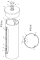
- FIG. 1b schematically shows a cartridge case 1 with a perspective view Cover 2.
- the cover 2 is also Stub sleeve called - deducted from the cartridge case 1.
- the cartridge case 1 On the inside of the cartridge case 1 are evenly distributed in the circumferential direction three webs 3 are arranged, which extend in the longitudinal direction of the cartridge case 1 stretch the entire length.
- the cartridge case 1 completely filled with propellant powder, so that the webs 3 in the Propellant powder protrude into it.
- the propellant powder is off Not shown for reasons of clarity.
- the bridges are the row after individual igniter 9 for the propellant powder embedded.
- the lighters 9 are connected to one another via a single-core or multi-core Bus line 4, the three webs 3 to an igniter 11 in Cap 2 of the cartridge case 1 leads. There is a bus line 4 for each web 3 intended.
- the igniter 11 consists of an ignition distributor 7 and one Contact screw 8. If the cartridge is to be fired, the Ignition piece 11 placed a contact element, not shown, which with a Fire control computer, not shown, is electrically connected. This means that Fire control computer in connection with the individual igniters 9 and can input data and read out.
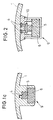
- Fig. 1 b shows a section across the cartridge case 1 according to Fig. 1a. It is good to recognize the three webs, which are arranged at 120 ° to each other and in which the igniters 9 are embedded.
- Fig. 1c shows the detail A from Fig. 1b shown enlarged with schematic shown lighter 9.
- a lighter 9 consists of an ignition charge 5 and optionally an amplifier charge 6.
- the reference numeral 4 is the Bus line indicated. The electronic unit is not shown.
- Fig. 2 shows a section similar to Fig. 1c, but with individual details.
- an electronic unit 10 is arranged in each igniter 9, e.g. B. a chip with integrated circuit or a circuit board with electronic Components.
- the bus line 4 is connected to this electronic unit 10.
- an ignition element is arranged, which at Ignition ignites the ignition charge 5, which in turn amplifies the charge 6 kindles. The spark plumes generated by this then ignite that Propellant powder.
- a temperature sensor is arranged or a temperature sensor is connected to the unit 10.
- a temperature sensor is connected to the unit 10.
- features of the propellant powder can be saved.
- the fire control computer Before firing, the fire control computer checks the temperature at the Ignition points and determines which igniters 9 are to be ignited or not. The fire control computer then programs the igniter 9 or the individual electronic units 10 accordingly. Will at the ignition an ignition pulse is emitted, then only the desired igniters 9 set on fire.
Landscapes
- Engineering & Computer Science (AREA)
- General Engineering & Computer Science (AREA)
- Air Bags (AREA)
- Ignition Installations For Internal Combustion Engines (AREA)
- Medicines Containing Material From Animals Or Micro-Organisms (AREA)
- Electrical Control Of Ignition Timing (AREA)
- Combined Controls Of Internal Combustion Engines (AREA)
Abstract
Description
- daß in der Hülse mehrere Anzünder angeordnet sind,
- daß alle Anzünder über eine programmierbare elektronische Einheit verfügen, in der eine individuelle Adresse gespeichert ist,
- daß die Anzünder über eine zwei- oder mehradrige Busleitung mit einem Anzündstück verbunden sind und
- daß das Anzündstück an einen Feuerleitrechner anschließbar ist.
- Ermitteln der Temperatur des Treibladungspulvers und Weiterleitung an den Feuerleitrechner,
- Auslesen individueller in der elektronischen Einheit 10 gespeicherter Merkmale des Treibladungspulvers und Weiterleitung dieser Daten an den Feuerleitrechner,
- Bestimmung im Feuerleitrechner der Anzahl und der zeitlichen Abfolge der zu zündenden Anzünder 9 und Programmierung dieser Anzünder (9),
- Aussenden eines Zündimpulses an die Anzünder 9.
- Fig. 1a
- schematisch eine Patronenhülse mit erfindungsgemäßer Mehrpunktanzündung,
- Fig. 1b
- einen Schnitt quer durch die Patronenhülse nach Fig. 1 a,
- Fig. 1c
- den Ausschnitt A aus Fig. 1b vergrößert dargestellt und
- Fig. 2
- einen Ausschnitt ähnlich Fig. 1c mit einzelnen Details.
Claims (10)
- Hochleistungsantrieb mit in einer Hülse (1) angeordnetem Treibladungspulver und einem pyrotechnischen Anzünder (9) zur Anzündung des Treibladungspulvers, wobei der Anzünder (9) einen Anzündsatz (5) und gegebenenfalls eine Verstärkerladung (6) enthält, dadurch gekennzeichnet,daß in der Hülse (1) mehrere Anzünder (9) angeordnet sind,daß alle Anzünder (9) über eine programmierbare elektronische Einheit (10) verfügen, in der eine individuelle Adresse gespeichert ist,daß die Anzünder (9) über eine zwei- oder mehradrige Busleitung (4) mit einem Anzündstück (11) verbunden sind unddaß das Anzündstück (11) an einen Feuerleitrechner anschließbar ist.
- Hochleistungsantrieb nach Anspruch 1, dadurch gekennzeichnet, daß im Anzünder (9) ein Temperatursensor zur Messung der Temperatur des Treibladungspulvers angeordnet ist.
- Hochleistungsantrieb nach Anspruch 1 oder 2, dadurch gekennzeichnet, daß in der elektronischen Einheit (10) abrufbare Merkmale des Treibladungspulvers gespeichert sind.
- Hochleistungsantrieb nach einem der Ansprüche 1 bis 3, dadurch gekennzeichnet, daß die Anzünder (9) fest mit der Innenseite der Hülse (1) verbunden sind.
- Hochleistungsantrieb nach einem der Ansprüche 1 bis 4, dadurch gekennzeichnet, daß die Anzünder (9) in auf der Innenseite der Hülse (1) verlaufenden Stegen (3) eingebettet sind.
- Hochleistungsantrieb nach einem der Ansprüche 1 bis 5, dadurch gekennzeichnet, daß die Hülse (1) voll-, teil- oder unverbrennbar ausgebildet ist.
- Hochleistungsantrieb nach einem der Ansprüche 1 bis 6, dadurch gekennzeichnet, daß das Anzündstück (11) in den stirnseitigen Verschlußdeckel (2) der Hülse (1) eingebettet ist.
- Hochleistungsantrieb nach einem der Ansprüche 1 bis 7, dadurch gekennzeichnet, daß das Anzündstück (11) einen Zündverteiler (7) und eine Kontaktschraube (8) enthält.
- Hochleistungsantrieb nach einem der Ansprüche 1 bis 8, dadurch gekennzeichnet, daß die Hochleistungsantriebe für Panzerbord- oder Artilleriemunition verwendet werden.
- Verfahren zum Anzünden eines Hochleistungsantriebs nach einem der Ansprüche 1 bis 9, gekennzeichnet durch einen oder mehrere der nachfolgend genannten Schritte:Ermitteln der Temperatur des Treibladungspulvers und Weiterleitung an den Feuerleitrechner,Auslesen individueller in der elektronischen Einheit (10) gespeicherter Merkmale des Treibladungspulvers und Weiterleitung dieser Daten an den Feuerleitrechner,Bestimmung im Feuerleitrechner der Anzahl und der zeitlichen Abfolge der zu zündenden Anzünder (9) und Programmierung dieser Anzünder (9),Aussenden eines Zündimpulses an die Anzünder (9).
Applications Claiming Priority (4)
| Application Number | Priority Date | Filing Date | Title |
|---|---|---|---|
| DE19955945 | 1999-11-19 | ||
| DE19955945 | 1999-11-19 | ||
| DE10024464A DE10024464A1 (de) | 1999-11-19 | 2000-05-18 | Mehrpunktanzündung für Hochleistungsantriebe, insbesondere für Munition |
| DE10024464 | 2000-05-18 |
Publications (3)
| Publication Number | Publication Date |
|---|---|
| EP1102029A2 true EP1102029A2 (de) | 2001-05-23 |
| EP1102029A3 EP1102029A3 (de) | 2002-06-12 |
| EP1102029B1 EP1102029B1 (de) | 2006-03-01 |
Family
ID=26005730
Family Applications (1)
| Application Number | Title | Priority Date | Filing Date |
|---|---|---|---|
| EP00123832A Expired - Lifetime EP1102029B1 (de) | 1999-11-19 | 2000-11-02 | Treibladung mit einer Mehrpunktanzündung |
Country Status (6)
| Country | Link |
|---|---|
| US (1) | US6543362B1 (de) |
| EP (1) | EP1102029B1 (de) |
| AT (1) | ATE319069T1 (de) |
| DE (1) | DE50012290D1 (de) |
| DK (1) | DK1102029T3 (de) |
| ES (1) | ES2261138T3 (de) |
Families Citing this family (9)
| Publication number | Priority date | Publication date | Assignee | Title |
|---|---|---|---|---|
| US7047885B1 (en) * | 2000-02-14 | 2006-05-23 | Alliant Techsystems Inc. | Multiple pulse cartridge ignition system |
| US6759624B2 (en) * | 2002-05-07 | 2004-07-06 | Ananda H. Kumar | Method and apparatus for heating a semiconductor wafer plasma reactor vacuum chamber |
| US7905178B2 (en) * | 2005-01-10 | 2011-03-15 | Raytheon Company | Methods and apparatus for selectable velocity projectile system |
| US7574960B1 (en) | 2005-11-29 | 2009-08-18 | The United States Of America As Represented By The Secretary Of The Navy | Ignition element |
| RU2327892C2 (ru) * | 2005-12-26 | 2008-06-27 | Александр Николаевич Бобров | Способ управления тягой ракетного двигателя на твердом топливе и заряд твердого топлива |
| JP4896922B2 (ja) * | 2008-05-01 | 2012-03-14 | 富士通株式会社 | 無線タグ及び無線タグを有する導電性パイプ |
| DE102009058566A1 (de) * | 2009-12-17 | 2011-06-22 | Krauss-Maffei Wegmann GmbH & Co. KG, 80997 | Treibladung sowie Vorrichtung und Verfahren zur Ermittlung einer Feuerleitlösung |
| US9506730B1 (en) * | 2016-02-04 | 2016-11-29 | Jake's Fireworks Inc. | Fireworks aerial display shell and method of use |
| US9885549B2 (en) * | 2016-02-04 | 2018-02-06 | Jake's Fireworks Inc. | Fireworks aerial display shell and method of use |
Family Cites Families (12)
| Publication number | Priority date | Publication date | Assignee | Title |
|---|---|---|---|---|
| US4823701A (en) * | 1984-09-28 | 1989-04-25 | The Boeing Company | Multi-point warhead initiation system |
| DE3516816C1 (de) * | 1985-05-10 | 1986-10-30 | Messerschmitt-Bölkow-Blohm GmbH, 8012 Ottobrunn | Anzuendeinrichtung fuer Treibladungen oder Gasgeneratoren |
| US4777881A (en) * | 1987-06-23 | 1988-10-18 | Honeywell Inc. | Temperature compensating electro-mechanical ballistic control tube system |
| US4930421A (en) * | 1988-07-11 | 1990-06-05 | The Boeing Company | Partitioned, fluid supported, high efficiency traveling charge for hyper-velocity guns |
| US5071496A (en) * | 1990-05-16 | 1991-12-10 | Eti Explosive Technologies International (Canada) | Low level blasting composition |
| US5323707A (en) * | 1991-08-05 | 1994-06-28 | Hercules Incorporated | Consumable low energy layered propellant casing |
| US5263416A (en) * | 1992-02-06 | 1993-11-23 | Alliant Techsystems Inc. | Primer propellant electrical ignition interconnect arrangement for single and multiple piece ammunition |
| GB9423313D0 (en) * | 1994-11-18 | 1995-01-11 | Explosive Dev Ltd | Improvements in or relating to detonation means |
| US5705766A (en) * | 1995-10-30 | 1998-01-06 | Motorola, Inc. | Electronic turns-counting fuze and method therefor |
| SE9704743L (sv) * | 1997-12-18 | 1999-01-11 | Foersvarets Forskningsanstalt | Sätt och elektrodanordning för styrning av en drivladdnings förbränningshastighet |
| DE19917633C1 (de) * | 1999-04-19 | 2000-11-23 | Fraunhofer Ges Forschung | Treibladungsanordnung für Rohrwaffen oder ballistische Antriebe |
| US7047885B1 (en) * | 2000-02-14 | 2006-05-23 | Alliant Techsystems Inc. | Multiple pulse cartridge ignition system |
-
2000
- 2000-11-02 ES ES00123832T patent/ES2261138T3/es not_active Expired - Lifetime
- 2000-11-02 AT AT00123832T patent/ATE319069T1/de not_active IP Right Cessation
- 2000-11-02 EP EP00123832A patent/EP1102029B1/de not_active Expired - Lifetime
- 2000-11-02 DE DE50012290T patent/DE50012290D1/de not_active Expired - Lifetime
- 2000-11-02 DK DK00123832T patent/DK1102029T3/da active
- 2000-11-20 US US09/714,950 patent/US6543362B1/en not_active Expired - Lifetime
Non-Patent Citations (1)
| Title |
|---|
| None |
Also Published As
| Publication number | Publication date |
|---|---|
| DE50012290D1 (de) | 2006-04-27 |
| EP1102029A3 (de) | 2002-06-12 |
| EP1102029B1 (de) | 2006-03-01 |
| ES2261138T3 (es) | 2006-11-16 |
| ATE319069T1 (de) | 2006-03-15 |
| DK1102029T3 (da) | 2006-07-03 |
| US6543362B1 (en) | 2003-04-08 |
Similar Documents
| Publication | Publication Date | Title |
|---|---|---|
| CH623409A5 (de) | ||
| DE2059665A1 (de) | Verfahren und Anordnung zum Ermitteln von spezifischen Munitionseigenschaften | |
| EP1102029B1 (de) | Treibladung mit einer Mehrpunktanzündung | |
| DE60110948T2 (de) | Treibladungskartusche mit einem mehrstufigen Anzündsystem | |
| DE2908217C2 (de) | Einheitsladung zur Vernebelung von Fahrzeugen | |
| DE69218650T2 (de) | Behälter, vorgesehen mit elektrischen Verbindungsmitteln | |
| DE2637848A1 (de) | Zuender fuer einen raketenmotor | |
| EP0255996A2 (de) | Patrone für Schusswaffen | |
| DE19546582C2 (de) | Manöverpatrone | |
| DE69925247T2 (de) | Verfahren zum zünden von geschütztreibladungen, geschütztreibladungsmodul und geschütztreibladung | |
| DE1578234A1 (de) | Elektrisches Gewehr und dafuer geeignete Munition | |
| DE10024464A1 (de) | Mehrpunktanzündung für Hochleistungsantriebe, insbesondere für Munition | |
| DE4041611A1 (de) | Munition | |
| DE19830134B4 (de) | Leuchtfackel für einen Hubschrauber und Verfahren zum Erzeugen einer Köderspur | |
| DE2726945A1 (de) | Ueb-geschoss fuer moerser o.dgl. | |
| DE19544560A1 (de) | Patrone | |
| DE2028539B2 (de) | Raketenmotor fur Festbrennstoffe | |
| DE19960392C2 (de) | Feuerwerksanlage sowie Verfahren zum Abschuss eines Feuerwerks | |
| DE3139525A1 (de) | Verfahren zum zuenden einer gaserzeugenden treibladungskartusche und konstruktion einer derartigen kartusche | |
| DE622923C (de) | Patrone fuer Handfeuerwaffen und Maschinengewehre mit mehreren Teilladungen | |
| EP1357349B1 (de) | Patrone | |
| DE2339294C3 (de) | Zündvorrichtung in einem hülsenlosen Pulverkörper | |
| CH632586A5 (de) | Elektrisches abfeuersystem, insbesondere fuer waffen zum verschiessen von munition mit verbrennbarer oder ohne treibladungshuelse. | |
| DE102022124558A1 (de) | Modulares Zündsystem sowie Munition umfassend ein modulares Zündsystem | |
| DE2410622C3 (de) | Zündvorrichtung in einem hülsenlosen Pulverkörper für leichte Rohrwaffen |
Legal Events
| Date | Code | Title | Description |
|---|---|---|---|
| PUAI | Public reference made under article 153(3) epc to a published international application that has entered the european phase |
Free format text: ORIGINAL CODE: 0009012 |
|
| AK | Designated contracting states |
Kind code of ref document: A2 Designated state(s): AT BE CH CY DE DK ES FI FR GB GR IE IT LI LU MC NL PT SE TR |
|
| AX | Request for extension of the european patent |
Free format text: AL;LT;LV;MK;RO;SI |
|
| PUAL | Search report despatched |
Free format text: ORIGINAL CODE: 0009013 |
|
| AK | Designated contracting states |
Kind code of ref document: A3 Designated state(s): AT BE CH CY DE DK ES FI FR GB GR IE IT LI LU MC NL PT SE TR |
|
| AX | Request for extension of the european patent |
Free format text: AL;LT;LV;MK;RO;SI |
|
| 17P | Request for examination filed |
Effective date: 20021212 |
|
| AKX | Designation fees paid |
Designated state(s): AT BE CH CY DE DK ES FI FR GB GR IE IT LI LU MC NL PT SE TR |
|
| 17Q | First examination report despatched |
Effective date: 20050411 |
|
| GRAP | Despatch of communication of intention to grant a patent |
Free format text: ORIGINAL CODE: EPIDOSNIGR1 |
|
| GRAS | Grant fee paid |
Free format text: ORIGINAL CODE: EPIDOSNIGR3 |
|
| RAP1 | Party data changed (applicant data changed or rights of an application transferred) |
Owner name: RUAG AMMOTEC GMBH |
|
| GRAA | (expected) grant |
Free format text: ORIGINAL CODE: 0009210 |
|
| AK | Designated contracting states |
Kind code of ref document: B1 Designated state(s): AT BE CH CY DE DK ES FI FR GB GR IE IT LI LU MC NL PT SE TR |
|
| PG25 | Lapsed in a contracting state [announced via postgrant information from national office to epo] |
Ref country code: IT Free format text: LAPSE BECAUSE OF FAILURE TO SUBMIT A TRANSLATION OF THE DESCRIPTION OR TO PAY THE FEE WITHIN THE PRESCRIBED TIME-LIMIT;WARNING: LAPSES OF ITALIAN PATENTS WITH EFFECTIVE DATE BEFORE 2007 MAY HAVE OCCURRED AT ANY TIME BEFORE 2007. THE CORRECT EFFECTIVE DATE MAY BE DIFFERENT FROM THE ONE RECORDED. Effective date: 20060301 Ref country code: IE Free format text: LAPSE BECAUSE OF FAILURE TO SUBMIT A TRANSLATION OF THE DESCRIPTION OR TO PAY THE FEE WITHIN THE PRESCRIBED TIME-LIMIT Effective date: 20060301 |
|
| REG | Reference to a national code |
Ref country code: GB Ref legal event code: FG4D Free format text: NOT ENGLISH |
|
| REG | Reference to a national code |
Ref country code: CH Ref legal event code: EP |
|
| REG | Reference to a national code |
Ref country code: IE Ref legal event code: FG4D Free format text: LANGUAGE OF EP DOCUMENT: GERMAN |
|
| REF | Corresponds to: |
Ref document number: 50012290 Country of ref document: DE Date of ref document: 20060427 Kind code of ref document: P |
|
| REG | Reference to a national code |
Ref country code: SE Ref legal event code: TRGR |
|
| GBT | Gb: translation of ep patent filed (gb section 77(6)(a)/1977) |
Effective date: 20060531 |
|
| REG | Reference to a national code |
Ref country code: GR Ref legal event code: EP Ref document number: 20060401844 Country of ref document: GR |
|
| REG | Reference to a national code |
Ref country code: DK Ref legal event code: T3 |
|
| PG25 | Lapsed in a contracting state [announced via postgrant information from national office to epo] |
Ref country code: PT Free format text: LAPSE BECAUSE OF FAILURE TO SUBMIT A TRANSLATION OF THE DESCRIPTION OR TO PAY THE FEE WITHIN THE PRESCRIBED TIME-LIMIT Effective date: 20060801 |
|
| REG | Reference to a national code |
Ref country code: CH Ref legal event code: NV Representative=s name: ISLER & PEDRAZZINI AG |
|
| REG | Reference to a national code |
Ref country code: IE Ref legal event code: FD4D |
|
| ET | Fr: translation filed | ||
| REG | Reference to a national code |
Ref country code: ES Ref legal event code: FG2A Ref document number: 2261138 Country of ref document: ES Kind code of ref document: T3 |
|
| PG25 | Lapsed in a contracting state [announced via postgrant information from national office to epo] |
Ref country code: BE Free format text: LAPSE BECAUSE OF NON-PAYMENT OF DUE FEES Effective date: 20061130 Ref country code: MC Free format text: LAPSE BECAUSE OF NON-PAYMENT OF DUE FEES Effective date: 20061130 |
|
| PLBE | No opposition filed within time limit |
Free format text: ORIGINAL CODE: 0009261 |
|
| STAA | Information on the status of an ep patent application or granted ep patent |
Free format text: STATUS: NO OPPOSITION FILED WITHIN TIME LIMIT |
|
| 26N | No opposition filed |
Effective date: 20061204 |
|
| REG | Reference to a national code |
Ref country code: CH Ref legal event code: PCAR Free format text: ISLER & PEDRAZZINI AG;POSTFACH 1772;8027 ZUERICH (CH) |
|
| BERE | Be: lapsed |
Owner name: RUAG AMMOTEC G.M.B.H. Effective date: 20061130 |
|
| PG25 | Lapsed in a contracting state [announced via postgrant information from national office to epo] |
Ref country code: AT Free format text: LAPSE BECAUSE OF NON-PAYMENT OF DUE FEES Effective date: 20061102 |
|
| PG25 | Lapsed in a contracting state [announced via postgrant information from national office to epo] |
Ref country code: TR Free format text: LAPSE BECAUSE OF FAILURE TO SUBMIT A TRANSLATION OF THE DESCRIPTION OR TO PAY THE FEE WITHIN THE PRESCRIBED TIME-LIMIT Effective date: 20060301 Ref country code: LU Free format text: LAPSE BECAUSE OF NON-PAYMENT OF DUE FEES Effective date: 20061102 |
|
| PG25 | Lapsed in a contracting state [announced via postgrant information from national office to epo] |
Ref country code: CY Free format text: LAPSE BECAUSE OF FAILURE TO SUBMIT A TRANSLATION OF THE DESCRIPTION OR TO PAY THE FEE WITHIN THE PRESCRIBED TIME-LIMIT Effective date: 20060301 |
|
| REG | Reference to a national code |
Ref country code: FR Ref legal event code: PLFP Year of fee payment: 16 |
|
| REG | Reference to a national code |
Ref country code: FR Ref legal event code: PLFP Year of fee payment: 17 |
|
| PGFP | Annual fee paid to national office [announced via postgrant information from national office to epo] |
Ref country code: DE Payment date: 20170124 Year of fee payment: 17 |
|
| REG | Reference to a national code |
Ref country code: FR Ref legal event code: PLFP Year of fee payment: 18 |
|
| REG | Reference to a national code |
Ref country code: DE Ref legal event code: R082 Ref document number: 50012290 Country of ref document: DE Representative=s name: BOEHMERT & BOEHMERT ANWALTSPARTNERSCHAFT MBB -, DE |
|
| PGFP | Annual fee paid to national office [announced via postgrant information from national office to epo] |
Ref country code: FI Payment date: 20171121 Year of fee payment: 18 Ref country code: NL Payment date: 20171120 Year of fee payment: 18 Ref country code: DK Payment date: 20171122 Year of fee payment: 18 Ref country code: FR Payment date: 20171121 Year of fee payment: 18 |
|
| PGFP | Annual fee paid to national office [announced via postgrant information from national office to epo] |
Ref country code: GB Payment date: 20171123 Year of fee payment: 18 Ref country code: GR Payment date: 20171114 Year of fee payment: 18 Ref country code: CH Payment date: 20171120 Year of fee payment: 18 Ref country code: IT Payment date: 20171124 Year of fee payment: 18 Ref country code: SE Payment date: 20171120 Year of fee payment: 18 Ref country code: ES Payment date: 20171220 Year of fee payment: 18 |
|
| REG | Reference to a national code |
Ref country code: DE Ref legal event code: R119 Ref document number: 50012290 Country of ref document: DE |
|
| PG25 | Lapsed in a contracting state [announced via postgrant information from national office to epo] |
Ref country code: DE Free format text: LAPSE BECAUSE OF NON-PAYMENT OF DUE FEES Effective date: 20180602 |
|
| REG | Reference to a national code |
Ref country code: DK Ref legal event code: EBP Effective date: 20181130 |
|
| REG | Reference to a national code |
Ref country code: CH Ref legal event code: PL |
|
| REG | Reference to a national code |
Ref country code: SE Ref legal event code: EUG |
|
| REG | Reference to a national code |
Ref country code: NL Ref legal event code: MM Effective date: 20181201 |
|
| GBPC | Gb: european patent ceased through non-payment of renewal fee |
Effective date: 20181102 |
|
| PG25 | Lapsed in a contracting state [announced via postgrant information from national office to epo] |
Ref country code: SE Free format text: LAPSE BECAUSE OF NON-PAYMENT OF DUE FEES Effective date: 20181103 Ref country code: FI Free format text: LAPSE BECAUSE OF NON-PAYMENT OF DUE FEES Effective date: 20181102 |
|
| PG25 | Lapsed in a contracting state [announced via postgrant information from national office to epo] |
Ref country code: NL Free format text: LAPSE BECAUSE OF NON-PAYMENT OF DUE FEES Effective date: 20181201 Ref country code: GR Free format text: LAPSE BECAUSE OF NON-PAYMENT OF DUE FEES Effective date: 20190605 Ref country code: CH Free format text: LAPSE BECAUSE OF NON-PAYMENT OF DUE FEES Effective date: 20181130 Ref country code: LI Free format text: LAPSE BECAUSE OF NON-PAYMENT OF DUE FEES Effective date: 20181130 |
|
| PG25 | Lapsed in a contracting state [announced via postgrant information from national office to epo] |
Ref country code: IT Free format text: LAPSE BECAUSE OF NON-PAYMENT OF DUE FEES Effective date: 20181102 Ref country code: FR Free format text: LAPSE BECAUSE OF NON-PAYMENT OF DUE FEES Effective date: 20181130 Ref country code: DK Free format text: LAPSE BECAUSE OF NON-PAYMENT OF DUE FEES Effective date: 20181130 |
|
| PG25 | Lapsed in a contracting state [announced via postgrant information from national office to epo] |
Ref country code: GB Free format text: LAPSE BECAUSE OF NON-PAYMENT OF DUE FEES Effective date: 20181102 |
|
| REG | Reference to a national code |
Ref country code: ES Ref legal event code: FD2A Effective date: 20200102 |
|
| PG25 | Lapsed in a contracting state [announced via postgrant information from national office to epo] |
Ref country code: ES Free format text: LAPSE BECAUSE OF NON-PAYMENT OF DUE FEES Effective date: 20181103 |