EP1102105B1 - Dispositif affichant une image comportant un prisme ayant une puissance optique - Google Patents
Dispositif affichant une image comportant un prisme ayant une puissance optique Download PDFInfo
- Publication number
- EP1102105B1 EP1102105B1 EP00119770A EP00119770A EP1102105B1 EP 1102105 B1 EP1102105 B1 EP 1102105B1 EP 00119770 A EP00119770 A EP 00119770A EP 00119770 A EP00119770 A EP 00119770A EP 1102105 B1 EP1102105 B1 EP 1102105B1
- Authority
- EP
- European Patent Office
- Prior art keywords
- local
- section
- prism body
- display apparatus
- image display
- Prior art date
- Legal status (The legal status is an assumption and is not a legal conclusion. Google has not performed a legal analysis and makes no representation as to the accuracy of the status listed.)
- Expired - Lifetime
Links
- 230000003287 optical effect Effects 0.000 title claims abstract description 85
- 239000000463 material Substances 0.000 claims description 6
- 210000001747 pupil Anatomy 0.000 claims description 6
- 230000004075 alteration Effects 0.000 description 38
- 239000011248 coating agent Substances 0.000 description 17
- 238000000576 coating method Methods 0.000 description 17
- 238000010586 diagram Methods 0.000 description 11
- 239000004973 liquid crystal related substance Substances 0.000 description 11
- 208000013057 hereditary mucoepithelial dysplasia Diseases 0.000 description 10
- 238000000926 separation method Methods 0.000 description 10
- 230000003247 decreasing effect Effects 0.000 description 9
- 230000007423 decrease Effects 0.000 description 5
- 229910052782 aluminium Inorganic materials 0.000 description 3
- XAGFODPZIPBFFR-UHFFFAOYSA-N aluminium Chemical compound [Al] XAGFODPZIPBFFR-UHFFFAOYSA-N 0.000 description 2
- 230000015572 biosynthetic process Effects 0.000 description 2
- 238000000034 method Methods 0.000 description 2
- 238000005452 bending Methods 0.000 description 1
- 238000004040 coloring Methods 0.000 description 1
- 230000000694 effects Effects 0.000 description 1
- 239000011521 glass Substances 0.000 description 1
- 210000003128 head Anatomy 0.000 description 1
- 238000003384 imaging method Methods 0.000 description 1
- 238000004519 manufacturing process Methods 0.000 description 1
- 229910052751 metal Inorganic materials 0.000 description 1
- 239000002184 metal Substances 0.000 description 1
- 230000002688 persistence Effects 0.000 description 1
- 229910052709 silver Inorganic materials 0.000 description 1
- 238000005549 size reduction Methods 0.000 description 1
Images


Classifications
-
- G—PHYSICS
- G02—OPTICS
- G02B—OPTICAL ELEMENTS, SYSTEMS OR APPARATUS
- G02B27/00—Optical systems or apparatus not provided for by any of the groups G02B1/00 - G02B26/00, G02B30/00
- G02B27/01—Head-up displays
- G02B27/017—Head mounted
- G02B27/0172—Head mounted characterised by optical features
Definitions
- the present invention relates to an image display apparatus and, more particularly, to the image display apparatus, for example, which is constructed using a liquid crystal display element as a display means for displaying an image and constructed to permit an observer to observe an enlarged image of image information displayed on the display element through a display optical system having a free surface prism properly set and which is suitably applicable to head-mounted displays (which will be referred to hereinafter as "HMDs”), goggle type displays, and so on.
- HMDs head-mounted displays
- goggle type displays goggle type displays
- the head-mounted displays which permitted the observer to observe an enlarged virtual image of the image information displayed on the image display element of liquid crystal or the like, for example, using an optical element provided with an entrance surface, a plurality of reflecting surfaces, and an exit surface in surfaces of a transparent body (prism).
- the HMDs with wider angles of view using a prism having surfaces with refractive powers differing depending upon azimuthal angles are proposed, for example, in Japanese Patent Application Laid-Open Nos. 10-75407, 9-146037, (10-282421,).
- the display optical system is constructed in such structure that a lens separate from the free surface prism is interposed between the eyes and the free surface prism, thereby achieving the wide horizontal angle of view of about 60°.
- US 5 790 311 A discloses an eyepiece for a head-mounted video display apparatus having three adjoining optical surfaces, constituting a prism with optical power with refractive powers differing depending upon the azimuthal angle.
- an important issue is to decrease the size and weight of the entire apparatus, because the apparatus is mounted on the observer's head.
- Another important issue is to allow the observer to observe the image information displayed on the display means, with a wide angle of view and in good order.
- the display optical system suggested in Japanese Patent Application Laid-Open No. 10-75407 includes a lens between the eyes and the free surface prism. This increases the size of the display optical system.
- three prisms are necessary for establishing a nearly non-power seethrough optical system while achieving approximate agreement between the eye optical axis and the outside optical axis (Fig. 15 of Laid-Open No. 10-75407), and thus the entire optical system tends to become great.
- An object of the present invention is to provide an image display apparatus that permits establishment of a compact display optical system and good correction for distortion and various aberrations and that is optimal for the HMDs with wide angles of view.
- Another object of the present invention is to provide an image display apparatus that permits observation of image information with a wide angle of view and with good image quality while decreasing the size of the entire apparatus and loss of light amount, by properly setting the structure of the display optical system including a free surface prism body for guiding light from the display means to the observer's eyes, in order to permit the observer to observe the image information displayed on the display means such as a liquid crystal display or the like.
- An image display apparatus according to one aspect of the present invention is specified in claim 1.
- a refractive index Nd of a material of said prism body 1.54 ⁇ Nd ⁇ 1.85.
- the following condition is satisfied by an angle ⁇ between the reference ray and a tangent line to the surface closest to the eye on the local generating-line section (meridional section) at the hit point between the reference ray and the surface of said prism body closest to the eye; 70° ⁇ ⁇ ⁇ 95°.
- said prism body comprises a transmitting surface, a reflecting surface, and a reflecting surface arranged in the order stated from the surface closest to said display means, and refractive powers on the local generating-line section (meridional section) at a hit point on each surface of the prism body, of a ray passing the center of the eye and a most marginal image on the far side from the eye out of most marginal images on the local generating-line section (meridional section) of the display means, are arranged in such arrangement that the transmitting surface of a negative refractive power, the reflecting surface of a positive refractive power, and the reflecting surface of a positive refractive power are placed in the order stated from the display means side.
- the surface closest to the eye is a surface having two functions of transmitting action and reflecting action.
- An image display apparatus is an image display apparatus comprising display means for displaying image information, optical means for guiding light from the display means to the eye, and seethrough means for guiding light from the outside to the eye, wherein said optical means comprises a prism body of a positive refractive power comprised of three or more different surfaces, inclusive of two or more surfaces with refractive powers differing depending upon azimuthal angles, wherein said seethrough means is constructed in such structure that a correction prism is placed adjacent to or joined to the prism body in said optical means, that adjacent surfaces or joint surfaces are partially transmitting surfaces with little optical refractive power, and that the eye optical axis is approximately aligned with the outside optical axis, wherein a surface of the seethrough means closest to the outside is a decentered, curved surface which has a shape different from that of a surface of the seethrough means closest to the eye and in which refractive powers differ depending upon azimuthal angles, and wherein the following condition is satisfied by a curvature radius 1
- said correction prism is placed in an outside region of said prism body.
- Fig. 1 is a schematic diagram to show the main part of the image display apparatus as a basis of the present invention.
- reference numeral 1 designates the display means for displaying an image including characters, graphics, etc., as an original image, which is comprised, for example, of a known liquid crystal display (LCD).
- Numeral 2 denotes a prism body (free surface prism body) of a positive refractive power having imaging action for guiding light from the display means 1 to the eyes (pupils) 7 of the observer.
- the light from the display means 1 is incident to an entrance surface 3 of the prism body 2, is then incident at an angle over the critical angle successively to a surface 4 and to a concave surface 5 to be totally reflected thereby, is incident thereafter at an angle of incidence below the critical angle this time to the surface 4 to emerge from the surface 4, and is guided to the eyes 7.
- the entrance surface 3 the surface 4, and the concave surface 5 of the prism body 2, thereby controlling decentering aberration in a low level.
- the curved surface is designed so as to satisfy the both functions of a transmissive surface and a reflective surface depending upon the critical angle condition for all beams of the incident light, thereby attaining the bright display optical system without loss in the light amount throughout the entire surface of the surface 4.
- the image information displayed on the display means 1 is observed as an enlarged virtual image through the prism body 2 from the pupil position 7.
- the prism body 2 constitutes an element of the display optical system.
- the concave surface 5 of the prism body 2 is formed as a mirror reflective surface of a deposited film of Al, Ag, or the like.
- the prism body 2 is constructed so as to make use of two reflections, but the prism body 2 may also be constructed using three or more reflections.
- the concave surface 5 can be formed as a half mirror surface to guide beams from the outside directly into the concave surface 5, or a correction prism body 6 can be used, as illustrated in Fig. 1, so as to use beams having passed through the prism body 6 and the prism body 2.
- the correction prism body 6 is used.
- the prism body 6 has a surface 6a of the same shape as the concave surface 5 of the prism body 2, and a light incident surface 6b, which is a plane, an aspherical surface, or a free curved surface.
- the concave surface 5 of the prism body 2 and the surface 6a of the prism body 6 are comprised of a half mirror surface.
- Beams from an object (not illustrated) in the outside are incident to the entrance surface 6b of the prism body 6, travel through the surface 6a, the concave surface 5, and the surface 4, and then are incident to the observer's pupils 7.
- the observer can observe both the image information displayed on the display means 1 and the object in the outside, in a common field.
- a field lens 11 may be interposed between the display means 1 and the entrance surface 3 of the prism body 2, as illustrated in Fig. 2.
- the beams from the display means 1 can be guided efficiently to the eyes 7.
- the apparatus includes the free surface prism body 2 and the relatively large liquid crystal device (in the diagonal size of about one inch or more), the apparatus assures the horizontal angle of view of 50° (the aspect ratio of 4 horizontal : 3 vertical), which is the minimum requirement in the fields of VR (virtual reality) and MR (mixed reality), and it permits attainment of a compact HMD with good optical performance and with capability of formation of the seethrough optical system.
- VR virtual reality
- MR mixed reality
- generating-line section (meridional section), sagittal section, reference ray, local generating-line section (meridional section), and local sagittal section used in the present invention.
- the yz section is the conventional generating-line section (meridional section)
- the xz section is the conventional sagittal section.
- these definitions are not effective, because there are cases wherein the surface vertex does not exist in an actual surface (i.e., the vertex is off the axis).
- the local generating-line section (meridional section) and local sagittal section for the decentered systems will be defined newly.
- the local generating-line section (meridional section) is defined as a plane including incident light and emergent light of a reference ray at an intersection, so called a hit point, between each surface and a ray passing the center of the image of the display means 1 (the center of the outside image in the seethrough case) and the center of the eye 7 (this ray will be referred to as a reference ray), and the local sagittal section as a plane being normal to the local generating-line section (meridional section) and parallel to the sagittal section in each surface vertex coordinate system while including the hit point.
- the features of the present invention will be described below, based on such definitions.
- the image display apparatus of the present embodiment has the display means 1 for displaying the image information and the optical means for guiding the light from the display means to the eye 7, the optical means has the prism body 2 of the positive refractive power including three or more surfaces with refractive powers differing depending upon azimuthal angles, the prism surface 3 of the prism body 2 closest to the display means 1 is the surface with refractive powers differing depending upon azimuthal angles, and a local curvature radius area of the prism surface 3 having a positive refractive power on the local generating-line section (meridional section) is placed between local curvature radius areas of the surface 3 having a negative refractive power on the local generating-line section (meridional section).
- the image on the liquid crystal display being the display means 1 is enlarged by the free surface prism body 2 of the positive refractive power to be observed by the observer, and it becomes harder to correct for marginal distortion and various aberrations (rotationally symmetric, general aberrations, and decentering aberration) with increase in the angle of view.
- the free curved surface is employed for the surface to which the main power of the prism is allotted (the concave surface 5 of Fig. 1), so as to decrease production of the decentering aberration at the main power surface.
- the decentering aberration remaining without being corrected for by the main power surface is corrected for by forming the other surface (the surface 4 of Fig. 1) close to the main power surface in such a surface shape of a free curved surface as to cancel the aberration. Only this design achieves correction for aberration to some extent, but the overall aberration balance is still unsatisfactory.
- the total aberration balance is improved by employing the free curved surface for the prism surface (the entrance surface 3 of Fig. 1) near the display means (LCD 1).
- the prism surface 3 closest to the display means 1 is formed in the surface shape to satisfy the feature of local curvature radii as described above to realize the wide angle of view, the entire system gives rise to little decentering distortion, has a good total aberration balance, and makes it relatively easier to assure the distance between the liquid crystal display or the field lens and the free surface prism body 2 (the distance will be referred to hereinafter as working distance).
- the marginal areas of the negative refractive power on the local generating-line section function to effect good correction for the decentering distortion, while the area of the positive refractive power near the center on the local generating-line section (meridional section) functions to assure the working distance.
- the prism body 2 has the transmitting surface 4, the reflecting surface 5, the reflecting surface 4, and the transmitting surface 3 in the reverse direction to the direction of passage of light, from the surface closest to the eyes 7.
- the prism body 2 is characterized in that the negative transmitting surface 4, the positive reflecting surface 5, and the negative reflecting surface 4 are arranged in the order named from the eye side, as to the refractive powers on the local sagittal section at the hit point of the reference ray on each prism surface.
- the light incident from the display means (liquid crystal display) 1 to the prism body 2 is bent on the local generating-line section (meridional section) by the above two reflecting surfaces (the concave surface 5 and the surface 4 in Fig. 1) and emerges from the transmitting surface 4 of the prism body 2 to be guided to the eyes 7.
- the thin prism body is attained thanks to this bending of rays.
- the prism surfaces are decentered on the local generating-line section (meridional section), correction needs to be made more for the decentering aberration than for the general aberrations (rotationally symmetric aberrations). Therefore, it is solved by employing the aforementioned local curvature radius condition.
- the general aberrations (rotationally symmetric aberrations) are corrected for well on the local sagittal section near the center of the image of the display means by employing the power arrangement to cancel the aberrations readily, wherein the refractive powers on the local sagittal section at the hit point between each prism surface and the reference ray are arranged in the order of the negative, positive, and negative refractive powers with symmetry from the eye side.
- the material of the prism body preferably has the refractive index Nd satisfying the following condition. 1.54 ⁇ Nd ⁇ 1.85
- a be an angle between the reference ray and a tangent line to the transmitting surface 4 on the local generating-line section (meridional section) and at the hit point between the reference ray and the transmitting surface 4 of the prism body 2 closest to the eyes 7. Then the angle ⁇ preferably satisfies the following condition. 70° ⁇ ⁇ ⁇ 95°
- Condition (2) is the condition for permitting the transmitting surface of the prism body 2 closest to the eye to act as the totally reflecting surface 4 and for defining the tilt decentering amount of the totally reflecting surface 4.
- the prism thickness becomes too large.
- the optical system will project far into the outside so as to increase the size.
- the surface 4 will be tilted more toward the outside and the tilt decentering amount of the concave surface 5 will also increase, so as to produce large decentering aberration and make it difficult to correct it.
- the transmitting surface 3, the reflecting surface 4, the reflecting surface 5, and the transmitting surface 4 are arranged in the order named from the surface 3 closest to the display means 1, and the negative transmitting surface, the positive reflecting surface, the positive reflecting surface, and the transmitting surface are arranged in the order named according to the passing order of light from the side of display means 1 as to the refractive powers on the local generating-line section (meridional section) at hit points of a ray passing the center of the eye and a most marginal image on the far side from the eye 7 out of most marginal images on the local generating-line section (meridional section) in the display means 1, on the prism surfaces.
- the light from the display means (liquid crystal display) 1 travels through the entrance surface 3 of the prism body 2, is totally reflected by the surface 4, is reflected by the concave surface 5, and then travels through the surface 4.
- the position of the lower part (F3) on the local generating-line section (meridional section) in the LCD 1 in Fig. 1 greatly affects the thickness of the HMD.
- the LCD For the rays emerging from the most marginal image (F3) on the local generating-line section (meridional section) in the LCD 1, when the prism surfaces are provided with the powers as described above, the LCD can be kept from projecting far into the outside, so that the HMD can be made thin.
- the rays emerging from the most marginal image (F3) travel via the above entrance surface 3, surface 4, and concave surface 5 and then are incident at an angle below the critical angle to the surface 4 to be transmitted thereby.
- the refractive power is positive on the local generating-line section (meridional section) at the hit point where the ray passing the position of the most marginal image F3 of the LCD 1 and the center of the eye 7 is transmitted by the surface 4. This allows sufficient correction for the aberration of the most marginal image (F3).
- the transmitting surface 4 closest to the eyes 7 is the surface having the both functions of transmitting action and totally reflecting action.
- This surface is the totally reflecting surface 4 and the two functions of the transmitting action and the totally reflecting action are used selectively depending upon the critical angle condition, thereby achieving the bright optical system without fundamental loss of light.
- a configuration is as follows for using the image display apparatus of the present invention as a seethrough optical system.
- the apparatus has the display means 1 for displaying the image information, the optical means 2 for guiding the light from the display means 1 to the eyes 7, and the seethrough optical system for guiding the light from the outside to the eyes 7.
- the optical means has the prism body 2 of the positive refractive power comprised of three or more different optical surfaces, inclusive of two or more surfaces with refractive powers differing depending upon azimuthal angles (free curved surfaces).
- the seethrough optical system is constructed in such structure that the separate correction prism 6 is placed adjacent to or joined to the prism body 2 in the optical means, the adjacent surfaces or joint surfaces are made as partially transmitting surfaces, the seethrough optical system has little optical refractive power, and the eye optical axis is approximately aligned with the outside optical axis.
- the decentered, curved surface 6b of the seethrough optical system closest to the outside is the surface with refractive powers differing depending upon azimuthal angles, which has the surface shape different from the curved surface 4 of the seethrough optical system closest to the eyes.
- the following condition (3) is preferably satisfied by the curvature radius l_ry on the local generating-line section (meridional section) and the curvature radius l_rx on the local sagittal section at the hit point of the reference ray on the decentered, curved surface 6b of the seethrough optical system closest to the outside.
- the prism body 2 When the free curved surfaces are adopted for the prism body 2, the focal lengths on the local generating-line section (meridional section) and on the local sagittal section of the free surface prism body cannot be made approximately equal unless there are at least two or more free curved surfaces. Therefore, the prism body is provided with two or more free curved surfaces.
- the correction prism 6 as illustrated in Fig. 1 is placed adjacent to or joined to the concave surface 5 of the free surface prism body 2, the concave surface 5 is formed as a half mirror, and the outside surface 6b of the correction prism 6 is designed so as to make the optical refractive power of the seethrough optical system almost null and so as to align the eye optical axis approximately with the outside optical axis.
- the surface 6b is formed in the surface shape different from that of the surface 4 of the seethrough optical system closest to the eyes, in order to suppress occurrence of aberration in the seethrough optical system.
- outside surface 6b of the correction prism 6 is the free curved surface and the curvature on the local generating-line section (meridional section) is set gentler than that on the local sagittal section, thereby decreasing the decentering aberration occurring on the local generating-line section (meridional section) in the seethrough optical system.
- the curved surface 4 of the seethrough optical system closest to the eyes is also the free curved surface, the curvature thereof on the local generating-line section (meridional section) is set gentler than that on the local sagittal section, the aberration of the seethrough optical system is canceled both on the local generating-line section (meridional section) and on the local sagittal section, and the seethrough optical system is designed to have no total refractive power both on the local generating-line section (meridional section) and on the local sagittal section.
- the correction prism 6 is placed on the outside of the prism body 2. Thanks to this structure, the display optical system functions well with only the free surface prism body 2 even if the correction prism 6 is taken off. Further, the seethrough optical system can be made up easily by separately preparing the display optical system and adding the correction prism to the outside surface of the display optical system later.
- the totally reflecting surface can be formed in such structure that a reflecting coating is provided in part of the area other than the transmitting area in the totally reflecting surface and a coating gradually decreasing its reflectance with decrease in the distance to the transmitting region is provided in the region between the reflecting coating area (for 100% reflection) and the transmitting area.
- a reflecting coating is provided in part of the area other than the transmitting area in the totally reflecting surface and a coating gradually decreasing its reflectance with decrease in the distance to the transmitting region is provided in the region between the reflecting coating area (for 100% reflection) and the transmitting area.
- the reflecting coating is provided in the LCD-side area 9 approximately equal to two thirds of the area other than the transmitting area on the local generating-line section (meridional section) in the total reflecting surface, and the coating with the reflectance gradually decreasing toward the transmitting area is provided in the rest area 10 approximately equal to one third.
- the reflecting coating area 9 and the coating area 10 with gradually decreasing reflectance both are preferably made of a metal mirror of aluminum or the like, because coloring is prevented.
- some rays out of those incident to the reflecting coating area 9 in the totally reflecting surface are incident at angles below the critical angle. The reason is as follows. If all the rays were made incident at angles over the critical angle to the surface 4 of the free surface prism body 2 to be totally reflected for attainment of a wider angle of view without light amount loss, remaining aberration (aberration of persistence of vision) would be large in the upper part of the screen.
- the reflecting coating is provided in the area 9 in the upper part of the surface 4, the light is incident at angles below the critical angle to the reflecting coating to be reflected thereby, and the light is totally reflected in the lower part of the surface 4 as before.
- the refractive powers on the local generating-line section (meridional section) at the hit points between the prism surfaces and the reference ray are arranged so that the prism surface (entrance surface 3) closest to the LCD 1 has the positive refractive power, the next reflecting surface (totally reflecting surface 4) has the negative refractive power, and the next reflecting surface (concave mirror 5) has the positive refractive power.
- This power arrangement works to cancel the decentering aberration occurring at the positive concave mirror 5 by the negative, total reflection surface 4 and to assure the working distance by the positive entrance surface 3.
- the refractive power is positive on the local generating-line section (meridional section) at the hit point between the reference ray and the transmitting surface (totally reflecting surface) 4 upon emergence from the prism body 2.
- the concave mirror 5 has the strongest positive refractive power and is tilted, thus producing large aberration.
- the positive power is allocated to the transmitting part of the surface 4 with relatively small tilt decentering, so as to decrease the load on the concave reflector, thus achieving good optical performance.
- the refractive powers were described previously on the local sagittal section at the hit points between the prism surfaces and the reference ray, and the same can also apply to the images in the upper part (F2) and in the lower part (F3) on the local generating-line section (meridional section) of LCD 1.
- the negative transmitting surface 4, the positive reflecting surface 5, the negative reflecting surface 4, and the transmitting surface 3 are arranged in the order stated from the side of eyes 7, as to the refractive powers on sections parallel to the local sagittal sections at the hit points on each prism surface, of the rays passing the center of the eye and the images of the upper part (F2) and the lower part (F3) on the local generating-line section (meridional section) of LCD 1.
- l_fx(2-5) be the total focal length of the entire system on the local sagittal section on the reference ray
- l_fx4 be the focal length of the surface 4 on the local sagittal section in the reflection action
- they are designed preferably to satisfy the following condition. -1.5 ⁇ l_fx4 / l_fx(2-5) ⁇ -0.5
- the negative power is too weak in the totally reflecting surface on the local sagittal section, and optical paths become long in the prism on the local sagittal section, thus increasing the thickness of the free surface prism body 2.
- F3l_fy4 be the focal length on the local generating-line section (meridional section) in reflection of the totally reflecting surface 4 on the ray passing the center of the eye 7 from the image F3 of the display means 1
- F3l_fy3 be the focal length on the local generating-line section (meridional section) of the concave surface 5 on the ray passing the center of the eye 7 from the image F3. Then they are designed preferably to satisfy the following condition. 0 ⁇ F3l_fy3 / F3l_fy4 ⁇ 1
- the power becomes negative on the local generating-line section (meridional section) in reflection of the totally reflecting surface 4 on the center ray of the eye 7 from the image F3, and the part of the image F3 of the LCD 1 will project far more into the outside.
- the positive power is too strong on the local generating-line section (meridional section) in reflection of the totally reflecting surface on the center ray of the eye 7 from the image F3
- a negative strong power is required on the local generating-line section (meridional section) in the entrance surface on the center ray of the eye 7 from the image F3, and the sufficient working distance cannot be assured in the part of optical paths from the image F3 of the LCD 1.
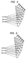
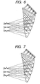
- Fig. 2 to Fig. 8 are cross-sectional views (local generating-line sections (meridional sections), indicated by suffix y) to show the main part of Numerical Examples 1 to 7, described hereinafter, of the image display apparatus of the present invention, and the vertex coordinate system of the first surface (eye 7) is presented in Fig. 1.
- Fig. 9 is a local generating-line sectional view of an example in which the optical system of Numerical Example 4 (Fig. 5) is applied to the seethrough optical system, in which ray tracing is presented in the state of passage in the forward direction from the outside.
- the vertex of each surface is decentered only with a shift in the direction of the y-axis and a tilt about the x-axis. Therefore, the general generating-line section (meridional section) and the local generating-line section (meridional section) are the same, but the general sagittal section of each surface is different from the local sagittal section.
- the general generating-line section (meridional section) and sagittal section described above are the definitions on the general-paraxial axis, whereas the local generating-line section (meridional section) and local sagittal section are the definitions on the local-paraxial axis described hereinafter.
- the definitions will also be given below for the local curvature radius, local surface separation, local focal length, and local refractive power for the decentered systems on the local-paraxial axis.
- the reference ray is defined as the center ray emerging from the center of the image of the display means 1 and entering the center of the observation surface (eye 7), and the local curvature radius, local surface separation, local focal length, and local refractive power with respect to the hit point (incident point) of the reference ray to each surface are used instead of the general curvature radius, surface separation, focal length, and refractive power with respect to the vertex of each surface.
- the local curvature radius means a local curvature radius (a radius of curvature on the local generating-line section (meridional section) or a radius of curvature on the local sagittal section) at the hit point on each optical surface.
- the local surface separation is a value of the distance between two hit points on a surface of interest and a next surface thereto (the distance on the reference ray, without reduction to air distance).
- the local focal length is a value calculated by the conventional focal length calculating method (paraxial tracing) from the local curvature radius, the refractive indexes before and after the surface, and the local surface separation.
- the local refractive power is a value of the reciprocal of the local focal length.
- Embodiments 1 to 7 Seven examples are presented as embodiments of the present invention.
- the numerical data of Embodiments 1 to 7 is presented in Tables 1 to 7 and the cross-sectional views of optical paths in Figs. 2 to 8.
- the numerical data for the seethrough optical system with addition of the correction prism body 6 to the prism body 2 of Embodiment 4 is presented in Table 8 and the cross-sectional view of optical paths thereof in Fig. 9.
- ry represents the generating-line section (meridional section) curvature radius, rx the sagittal section curvature radius, d the surface separation (in parallel to the vertex coordinate system of the first surface), "shift” and “tilt” decentering amounts ("shift” indicating a parallel decentering amount of the surface vertex of each surface with respect to the vertex coordinate system of the first surface and “tilt” a tilt decentering amount, on the generating-line section (meridional section)), and the refractive index for the d-line, vd the Abbe's number, and FFS the free curved surface.
- Each element with M represents a reflecting surface and the refractive index nd thereof for the d-line is given an opposite sign.
- Tables 1 to 7 show the numerical data obtained by reverse tracing from the eye 7 to the liquid crystal side (display means) 1, and Table 8 the numerical data obtained by forward tracing of light from the object toward the pupil (7).
- the defining equation of FFS (free curved surface) is given as follows.
- the tables also include the actual generating-line section (meridional section) curvature radius ry and sagittal section curvature radius rx at the point (0, 0), i.e., on the surface vertex.)
- the tables include the local curvature radii local_ry, local _ rx, the local surface separation local_d (with a reverse sign for a reflecting surface), the local focal lengths local_fy, local_fx, and the refractive index nd of surface (with a reverse sign for a reflecting surface).
- the tables also include the hit point coordinates on each surface (with the vertex at 0, 0), the overall local focal lengths, and the angles of view.
- local paraxial ray ⁇ F2> including the local curvature radii local_ry, local_rx, local surface separation local_d (with a reverse sign for a reflecting surface), local focal lengths local_fy, local_fx, refractive index nd of surface (with a reverse sign for a reflecting surface), hit point coordinates on each surface (with the vertex at 0, 0), and overall local focal lengths, at the hit point between each surface and the ray passing the center of the eye and the most marginal image F2 (upper part) of the LCD on the local generating-line section (meridional section) of the LCD, different from the hit point between the reference ray and each surface.
- the numerical data and calculated values in this case were computed by replacing the reference ray of the local-paraxial axis (the ray passing the center of the eye and the center of the LCD) with the ray passing the center of the eye and the most marginal image F2 (upper part) of the LCD.
- the data is also added similarly as local paraxial ray ⁇ F3> for the most marginal image F3 (lower part) of the LCD.
- Table 9 includes lists of the following data for seven Embodiments 1 to 7: the local generating-line section (meridional section) focal length and local sagittal section focal length (on the reference ray) of each surface and the entire system; the local generating-line section (meridional section) focal length and local sagittal section focal length of each surface and the entire system on the ray from F2 to the center of the eye; the local generating-line section (meridional section) focal length and local sagittal section focal length of each surface and the entire system on the ray from F3 to the center of the eye.
- the present invention permits formation of the compact display optical system and achievement of the image display apparatus optimal for the HMDs with wide angles of view and with good correction for the distortion and various aberrations.
- the present invention permits attainment of the image display apparatus that allows the observer to observe the image information with a wide angle of view and with good image quality while decreasing the loss of optical amount and the size of the entire apparatus, by properly setting the structure of the display optical system including the free surface prism body for guiding the light from the display means to the observer's eyes in order to permit the observer to observe the image information displayed on the display means such as the liquid crystal display or the like.
Landscapes
- Physics & Mathematics (AREA)
- General Physics & Mathematics (AREA)
- Optics & Photonics (AREA)
- Devices For Indicating Variable Information By Combining Individual Elements (AREA)
- Lenses (AREA)
Claims (7)
- Appareil d'affichage d'images, comportant un moyen d'affichage (1) destiné à afficher une information d'image, et un moyen optique (2, 11) destiné à guider de la lumière depuis le moyen d'affichage (1) vers l'oeil d'un observateur,
dans lequel ledit moyen optique (2, 11) comporte un corps de prisme (2) d'une puissance de réfraction positive, ayant trois ou plus de trois surfaces (3, 4, 5) avec des puissances de réfraction différant suivant les angles d'azimut,
dans lequel ledit corps de prisme (2) présente une surface transmissive (4) de sortie, une première surface réfléchissante (5), une seconde surface réfléchissante (4) qui est identique à ladite surface transmissive (4) de sortie et une surface transmissive (3) d'entrée placée de façon à être la plus proche du moyen d'affichage (1), ces surfaces étant agencées dans l'ordre cité dans le sens inverse du sens de passage de la lumière depuis le moyen d'affichage (1), et
dans lequel ladite surface d'entrée (3) est une surface dont les puissances de réfraction diffèrent suivant les angles d'azimut,
caractérisé en ce que
ladite surface d'entrée (3) est une surface dans laquelle une zone de rayon de courbure locale ayant une puissance de réfraction positive sur une section méridienne locale est interposée entre des zones de rayon de courbure locales ayant une puissance de réfraction négative sur la section méridienne locale, et
en ce que les puissances de réfraction sur une section sagittale locale à des points d'intersection entre un chemin de référence, qui est défini par un rayon de lumière passant par le centre du moyen d'affichage (1) et le centre de la pupille de sortie (7) de l'appareil d'affichage d'images, et les surfaces respectives (4, 5) du corps de prisme (2) sont agencées de façon que la surface de sortie (4) ait une puissance de réfraction négative sur la section sagittale locale, que la première surface réfléchissante (5) ait une puissance positive sur la section sagittale locale et que la seconde surface réfléchissante (4) ait une puissance négative sur la section sagittale locale. - Appareil d'affichage d'images selon la revendication 1, dans lequel la condition suivante est satisfaite par l'indice de réfraction Nd de la matière du corps de prisme (2) :
- Appareil d'affichage d'images selon la revendication 1 ou 2, dans lequel la condition suivante est satisfaite par un angle α entre le chemin d'un rayon de référence et une tangente à la surface de sortie (4) sur la section méridienne locale au point d'intersection entre le chemin du rayon de référence et la surface de sortie (4) :
- Appareil d'affichage d'images selon l'une des revendications 1 à 3, dans lequel le corps de prisme présente ladite surface d'entrée (3), une surface réfléchissante (4) et une autre surface réfléchissante (5) agencées dans l'ordre cité à partir de ladite surface d'entrée (3), et dans lequel les puissances de réfraction sur une section méridienne locale à des points d'intersection entre les surfaces respectives (3, 4, 5) du corps de prisme (2) et un chemin d'un rayon marginal, qui est défini par un rayon passant par le centre de la pupille de sortie (7) de l'appareil et l'image la plus marginale (F3) sur le côté inférieur du moyen d'affichage (1) sur la section méridienne locale, sont agencées de façon que ladite surface d'entrée (3) ait une puissance de réfraction négative sur la section méridienne locale, que la surface réfléchissante (4) ait une puissance de réfraction positive sur la section méridienne locale et que l'autre surface réfléchissante (5) ait une puissance de réfraction positive sur la section méridienne locale.
- Appareil d'affichage d'images selon la revendication 4, dans lequel la surface de sortie (4) est une surface ayant la fonction de transmission et ayant en outre une fonction de réflexion.
- Appareil d'affichage d'images selon la revendication 1, dans lequel la condition suivante
- Appareil d'affichage d'images selon la revendication 4, dans lequel la condition suivante
Applications Claiming Priority (2)
| Application Number | Priority Date | Filing Date | Title |
|---|---|---|---|
| JP32959799 | 1999-11-19 | ||
| JP32959799A JP3854763B2 (ja) | 1999-11-19 | 1999-11-19 | 画像表示装置 |
Publications (2)
| Publication Number | Publication Date |
|---|---|
| EP1102105A1 EP1102105A1 (fr) | 2001-05-23 |
| EP1102105B1 true EP1102105B1 (fr) | 2005-12-07 |
Family
ID=18223137
Family Applications (1)
| Application Number | Title | Priority Date | Filing Date |
|---|---|---|---|
| EP00119770A Expired - Lifetime EP1102105B1 (fr) | 1999-11-19 | 2000-09-11 | Dispositif affichant une image comportant un prisme ayant une puissance optique |
Country Status (5)
| Country | Link |
|---|---|
| US (1) | US6384983B1 (fr) |
| EP (1) | EP1102105B1 (fr) |
| JP (1) | JP3854763B2 (fr) |
| AT (1) | ATE312368T1 (fr) |
| DE (1) | DE60024569T2 (fr) |
Families Citing this family (57)
| Publication number | Priority date | Publication date | Assignee | Title |
|---|---|---|---|---|
| JP2001142025A (ja) * | 1999-11-17 | 2001-05-25 | Mixed Reality Systems Laboratory Inc | 画像表示装置 |
| JP3854763B2 (ja) * | 1999-11-19 | 2006-12-06 | キヤノン株式会社 | 画像表示装置 |
| JP4272785B2 (ja) * | 2000-01-17 | 2009-06-03 | キヤノン株式会社 | 光学処理方法およびそれを用いた光学処理装置 |
| JP2002258208A (ja) * | 2001-03-01 | 2002-09-11 | Mixed Reality Systems Laboratory Inc | 光学素子及びそれを用いた複合表示装置 |
| KR20030088217A (ko) * | 2002-05-13 | 2003-11-19 | 삼성전자주식회사 | 배율 조정이 가능한 착용형 디스플레이 시스템 |
| DE102005017207A1 (de) * | 2005-04-14 | 2006-10-19 | Carl Zeiss Jena Gmbh | Projektionseinheit für ein Head-Up-Display |
| US8511827B2 (en) | 2008-01-22 | 2013-08-20 | The Arizona Board Of Regents On Behalf Of The University Of Arizona | Head-mounted projection display using reflective microdisplays |
| US8638483B2 (en) | 2008-09-17 | 2014-01-28 | Konica Minolta Holdings, Inc. | Image display device and head-mounted display |
| WO2010123934A1 (fr) * | 2009-04-20 | 2010-10-28 | The Arizona Board Of Regents On Behalf Of The University Of Arizona | Visiocasque sans forme à transparence optique |
| US20110075257A1 (en) | 2009-09-14 | 2011-03-31 | The Arizona Board Of Regents On Behalf Of The University Of Arizona | 3-Dimensional electro-optical see-through displays |
| JP5457775B2 (ja) * | 2009-09-30 | 2014-04-02 | オリンパス株式会社 | 光学系 |
| US9366862B2 (en) | 2010-02-28 | 2016-06-14 | Microsoft Technology Licensing, Llc | System and method for delivering content to a group of see-through near eye display eyepieces |
| US9223134B2 (en) | 2010-02-28 | 2015-12-29 | Microsoft Technology Licensing, Llc | Optical imperfections in a light transmissive illumination system for see-through near-eye display glasses |
| US8467133B2 (en) | 2010-02-28 | 2013-06-18 | Osterhout Group, Inc. | See-through display with an optical assembly including a wedge-shaped illumination system |
| US9091851B2 (en) | 2010-02-28 | 2015-07-28 | Microsoft Technology Licensing, Llc | Light control in head mounted displays |
| US9128281B2 (en) | 2010-09-14 | 2015-09-08 | Microsoft Technology Licensing, Llc | Eyepiece with uniformly illuminated reflective display |
| US8482859B2 (en) | 2010-02-28 | 2013-07-09 | Osterhout Group, Inc. | See-through near-eye display glasses wherein image light is transmitted to and reflected from an optically flat film |
| US9097890B2 (en) | 2010-02-28 | 2015-08-04 | Microsoft Technology Licensing, Llc | Grating in a light transmissive illumination system for see-through near-eye display glasses |
| US20150309316A1 (en) | 2011-04-06 | 2015-10-29 | Microsoft Technology Licensing, Llc | Ar glasses with predictive control of external device based on event input |
| US8472120B2 (en) | 2010-02-28 | 2013-06-25 | Osterhout Group, Inc. | See-through near-eye display glasses with a small scale image source |
| US8488246B2 (en) | 2010-02-28 | 2013-07-16 | Osterhout Group, Inc. | See-through near-eye display glasses including a curved polarizing film in the image source, a partially reflective, partially transmitting optical element and an optically flat film |
| US9759917B2 (en) | 2010-02-28 | 2017-09-12 | Microsoft Technology Licensing, Llc | AR glasses with event and sensor triggered AR eyepiece interface to external devices |
| US9182596B2 (en) | 2010-02-28 | 2015-11-10 | Microsoft Technology Licensing, Llc | See-through near-eye display glasses with the optical assembly including absorptive polarizers or anti-reflective coatings to reduce stray light |
| US9134534B2 (en) | 2010-02-28 | 2015-09-15 | Microsoft Technology Licensing, Llc | See-through near-eye display glasses including a modular image source |
| US8477425B2 (en) | 2010-02-28 | 2013-07-02 | Osterhout Group, Inc. | See-through near-eye display glasses including a partially reflective, partially transmitting optical element |
| CN102906623A (zh) | 2010-02-28 | 2013-01-30 | 奥斯特豪特集团有限公司 | 交互式头戴目镜上的本地广告内容 |
| US20120249797A1 (en) | 2010-02-28 | 2012-10-04 | Osterhout Group, Inc. | Head-worn adaptive display |
| US9229227B2 (en) | 2010-02-28 | 2016-01-05 | Microsoft Technology Licensing, Llc | See-through near-eye display glasses with a light transmissive wedge shaped illumination system |
| US9097891B2 (en) | 2010-02-28 | 2015-08-04 | Microsoft Technology Licensing, Llc | See-through near-eye display glasses including an auto-brightness control for the display brightness based on the brightness in the environment |
| US9129295B2 (en) | 2010-02-28 | 2015-09-08 | Microsoft Technology Licensing, Llc | See-through near-eye display glasses with a fast response photochromic film system for quick transition from dark to clear |
| US9341843B2 (en) | 2010-02-28 | 2016-05-17 | Microsoft Technology Licensing, Llc | See-through near-eye display glasses with a small scale image source |
| US9285589B2 (en) | 2010-02-28 | 2016-03-15 | Microsoft Technology Licensing, Llc | AR glasses with event and sensor triggered control of AR eyepiece applications |
| US10180572B2 (en) | 2010-02-28 | 2019-01-15 | Microsoft Technology Licensing, Llc | AR glasses with event and user action control of external applications |
| WO2011134169A1 (fr) | 2010-04-30 | 2011-11-03 | Beijing Institute Of Technology | Dispositif d'affichage par pavés monté sur la tête à grand angle et haute définition |
| AU2011348122A1 (en) * | 2010-12-24 | 2013-07-11 | Magic Leap Inc. | An ergonomic head mounted display device and optical system |
| KR101931406B1 (ko) | 2012-01-24 | 2018-12-20 | 더 아리조나 보드 오브 리전츠 온 비핼프 오브 더 유니버시티 오브 아리조나 | 컴팩트한 시선추적 기능의 헤드 탑재형 디스플레이 |
| WO2013182212A1 (fr) | 2012-06-05 | 2013-12-12 | Volvo Lastvagnar Ab | Appareil électrique et procédé pour alimenter une machine électrique |
| IN2015DN02476A (fr) * | 2012-10-18 | 2015-09-11 | Univ Arizona State | |
| JP6244631B2 (ja) * | 2013-02-19 | 2017-12-13 | セイコーエプソン株式会社 | 虚像表示装置 |
| JP6330258B2 (ja) * | 2013-05-15 | 2018-05-30 | セイコーエプソン株式会社 | 虚像表示装置 |
| US9335548B1 (en) | 2013-08-21 | 2016-05-10 | Google Inc. | Head-wearable display with collimated light source and beam steering mechanism |
| CN107219628B (zh) * | 2013-11-27 | 2020-05-01 | 奇跃公司 | 虚拟和增强现实系统与方法 |
| US9690763B1 (en) | 2013-12-17 | 2017-06-27 | Bryant Christopher Lee | Display of webpage elements on a connected computer |
| JP6630465B2 (ja) * | 2014-03-05 | 2020-01-15 | アリゾナ ボード オブ リージェンツ オン ビハーフ オブ ザ ユニバーシティ オブ アリゾナ | 可変焦点および/または物体認識を備えたウェアラブル3d拡張現実ディスプレイ |
| US10634916B2 (en) | 2014-12-17 | 2020-04-28 | Lg Innotek Co., Ltd. | Wearable display device |
| US10176961B2 (en) | 2015-02-09 | 2019-01-08 | The Arizona Board Of Regents On Behalf Of The University Of Arizona | Small portable night vision system |
| JP2017026898A (ja) * | 2015-07-24 | 2017-02-02 | キヤノン株式会社 | 画像表示装置および光学素子 |
| US10739578B2 (en) | 2016-08-12 | 2020-08-11 | The Arizona Board Of Regents On Behalf Of The University Of Arizona | High-resolution freeform eyepiece design with a large exit pupil |
| WO2018161040A1 (fr) * | 2017-03-02 | 2018-09-07 | Intevac, Inc. | Prisme d'ordre supérieur axial transparent |
| EP3593195B1 (fr) | 2017-03-09 | 2023-12-06 | ARIZONA BOARD OF REGENTS on behalf of THE UNIVERSITY OF ARIZONA | Affichage de champ lumineux monté sur la tête avec imagerie intégrale et optique de relais |
| KR102611752B1 (ko) | 2017-03-09 | 2023-12-07 | 아리조나 보드 오브 리전츠 온 비해프 오브 더 유니버시티 오브 아리조나 | 통합 이미징 및 도파관 프리즘을 구비한 헤드 장착 광 필드 디스플레이 |
| CN111869204B (zh) | 2018-03-22 | 2023-10-03 | 亚利桑那大学评议会 | 为基于积分成像的光场显示来渲染光场图像的方法 |
| US11210772B2 (en) | 2019-01-11 | 2021-12-28 | Universal City Studios Llc | Wearable visualization device systems and methods |
| CN111624767B (zh) * | 2019-02-28 | 2022-03-04 | 京东方科技集团股份有限公司 | 近眼显示装置 |
| CN116413911B (zh) * | 2021-12-31 | 2025-08-01 | 北京耐德佳显示技术有限公司 | 一种超薄型镜片、使用其的虚像成像装置和近眼显示器 |
| US20240004199A1 (en) * | 2022-07-01 | 2024-01-04 | Google Llc | Partially curved lightguide with pupil replicators |
| US20250044519A1 (en) * | 2023-08-02 | 2025-02-06 | Meta Platforms Technologies, Llc | Micro-molded prism geometric waveguide |
Family Cites Families (10)
| Publication number | Priority date | Publication date | Assignee | Title |
|---|---|---|---|---|
| GB9217058D0 (en) * | 1992-08-12 | 1992-11-04 | Marconi Gec Ltd | Display system |
| GB9301769D0 (en) * | 1993-01-29 | 1993-03-17 | Ind Limited W | Opticla system |
| JP3245478B2 (ja) * | 1993-04-27 | 2002-01-15 | オリンパス光学工業株式会社 | 頭部装着式表示装置 |
| JP3599828B2 (ja) * | 1995-05-18 | 2004-12-08 | オリンパス株式会社 | 光学装置 |
| JP3676472B2 (ja) * | 1996-01-19 | 2005-07-27 | オリンパス株式会社 | 接眼光学系 |
| JPH10239630A (ja) * | 1996-12-24 | 1998-09-11 | Olympus Optical Co Ltd | 画像表示装置 |
| JPH10239631A (ja) * | 1996-12-24 | 1998-09-11 | Olympus Optical Co Ltd | 頭部装着型画像表示装置 |
| JP3279265B2 (ja) * | 1998-03-26 | 2002-04-30 | 株式会社エム・アール・システム研究所 | 画像表示装置 |
| JP2000075240A (ja) * | 1998-08-26 | 2000-03-14 | Mr System Kenkyusho:Kk | 複合表示装置 |
| JP3854763B2 (ja) * | 1999-11-19 | 2006-12-06 | キヤノン株式会社 | 画像表示装置 |
-
1999
- 1999-11-19 JP JP32959799A patent/JP3854763B2/ja not_active Expired - Fee Related
-
2000
- 2000-09-08 US US09/658,665 patent/US6384983B1/en not_active Expired - Lifetime
- 2000-09-11 EP EP00119770A patent/EP1102105B1/fr not_active Expired - Lifetime
- 2000-09-11 AT AT00119770T patent/ATE312368T1/de not_active IP Right Cessation
- 2000-09-11 DE DE60024569T patent/DE60024569T2/de not_active Expired - Lifetime
Also Published As
| Publication number | Publication date |
|---|---|
| EP1102105A1 (fr) | 2001-05-23 |
| DE60024569T2 (de) | 2006-07-27 |
| ATE312368T1 (de) | 2005-12-15 |
| DE60024569D1 (de) | 2006-01-12 |
| JP2001147400A (ja) | 2001-05-29 |
| US6384983B1 (en) | 2002-05-07 |
| JP3854763B2 (ja) | 2006-12-06 |
Similar Documents
| Publication | Publication Date | Title |
|---|---|---|
| EP1102105B1 (fr) | Dispositif affichant une image comportant un prisme ayant une puissance optique | |
| US11609430B2 (en) | Wide angle and high resolution tiled head-mounted display device | |
| US5699194A (en) | Image display apparatus comprising an internally reflecting ocular optical system | |
| US7081999B2 (en) | Image display apparatus and head mounted display using it | |
| US7864459B2 (en) | Image display apparatus | |
| US7408715B2 (en) | Image display apparatus and image display system | |
| JP3847799B2 (ja) | 視線検出系を有した表示装置 | |
| EP1150155A2 (fr) | Dispositif d'affichage d'image et système optique | |
| US8437087B2 (en) | Observation optical system and image display apparatus | |
| US6687057B1 (en) | Image display apparatus having rotationally asymmetric phase distribution | |
| JP2004341411A (ja) | 光学系および画像表示装置 | |
| US5777794A (en) | Image display apparatus | |
| US20040184152A1 (en) | Optical system, display optical system and image-taking optical system | |
| JP3486465B2 (ja) | 視覚表示装置 | |
| JP3977021B2 (ja) | 画像表示装置及びそれを用いたヘッドマウントディスプレイ | |
| US7675685B2 (en) | Image display apparatus | |
| JP3977002B2 (ja) | 画像表示装置及びそれを用いたヘッドマウントディスプレイ | |
| JP3957961B2 (ja) | 画像表示装置及びそれを用いたヘッドマウントディスプレイ | |
| JP2004185023A (ja) | 画像表示装置 | |
| JP3870076B2 (ja) | 画像表示装置および撮像装置 | |
| JP3870071B2 (ja) | 画像表示装置および撮像装置 | |
| JP3870073B2 (ja) | 画像表示装置および撮像装置 | |
| JP3870072B2 (ja) | 画像表示装置および撮像装置 | |
| JP3870075B2 (ja) | 画像表示装置および撮像装置 | |
| JP3870070B2 (ja) | 画像表示装置および撮像装置 |
Legal Events
| Date | Code | Title | Description |
|---|---|---|---|
| PUAI | Public reference made under article 153(3) epc to a published international application that has entered the european phase |
Free format text: ORIGINAL CODE: 0009012 |
|
| AK | Designated contracting states |
Kind code of ref document: A1 Designated state(s): AT BE CH CY DE DK ES FI FR GB GR IE IT LI LU MC NL PT SE |
|
| AX | Request for extension of the european patent |
Free format text: AL;LT;LV;MK;RO;SI |
|
| 17P | Request for examination filed |
Effective date: 20011031 |
|
| AKX | Designation fees paid |
Free format text: AT BE CH CY DE DK ES FI FR GB GR IE IT LI LU MC NL PT SE |
|
| RAP1 | Party data changed (applicant data changed or rights of an application transferred) |
Owner name: CANON KABUSHIKI KAISHA |
|
| 17Q | First examination report despatched |
Effective date: 20040420 |
|
| RTI1 | Title (correction) |
Free format text: IMAGE DISPLAY APPARATUS WITH A PRISM HAVING OPTICAL POWER |
|
| GRAP | Despatch of communication of intention to grant a patent |
Free format text: ORIGINAL CODE: EPIDOSNIGR1 |
|
| GRAS | Grant fee paid |
Free format text: ORIGINAL CODE: EPIDOSNIGR3 |
|
| GRAA | (expected) grant |
Free format text: ORIGINAL CODE: 0009210 |
|
| AK | Designated contracting states |
Kind code of ref document: B1 Designated state(s): AT BE CH CY DE DK ES FI FR GB GR IE IT LI LU MC NL PT SE |
|
| PG25 | Lapsed in a contracting state [announced via postgrant information from national office to epo] |
Ref country code: IT Free format text: LAPSE BECAUSE OF FAILURE TO SUBMIT A TRANSLATION OF THE DESCRIPTION OR TO PAY THE FEE WITHIN THE PRESCRIBED TIME-LIMIT;WARNING: LAPSES OF ITALIAN PATENTS WITH EFFECTIVE DATE BEFORE 2007 MAY HAVE OCCURRED AT ANY TIME BEFORE 2007. THE CORRECT EFFECTIVE DATE MAY BE DIFFERENT FROM THE ONE RECORDED. Effective date: 20051207 Ref country code: FI Free format text: LAPSE BECAUSE OF FAILURE TO SUBMIT A TRANSLATION OF THE DESCRIPTION OR TO PAY THE FEE WITHIN THE PRESCRIBED TIME-LIMIT Effective date: 20051207 Ref country code: BE Free format text: LAPSE BECAUSE OF FAILURE TO SUBMIT A TRANSLATION OF THE DESCRIPTION OR TO PAY THE FEE WITHIN THE PRESCRIBED TIME-LIMIT Effective date: 20051207 Ref country code: AT Free format text: LAPSE BECAUSE OF FAILURE TO SUBMIT A TRANSLATION OF THE DESCRIPTION OR TO PAY THE FEE WITHIN THE PRESCRIBED TIME-LIMIT Effective date: 20051207 Ref country code: CH Free format text: LAPSE BECAUSE OF FAILURE TO SUBMIT A TRANSLATION OF THE DESCRIPTION OR TO PAY THE FEE WITHIN THE PRESCRIBED TIME-LIMIT Effective date: 20051207 Ref country code: LI Free format text: LAPSE BECAUSE OF FAILURE TO SUBMIT A TRANSLATION OF THE DESCRIPTION OR TO PAY THE FEE WITHIN THE PRESCRIBED TIME-LIMIT Effective date: 20051207 |
|
| REG | Reference to a national code |
Ref country code: GB Ref legal event code: FG4D |
|
| REG | Reference to a national code |
Ref country code: CH Ref legal event code: EP |
|
| REG | Reference to a national code |
Ref country code: IE Ref legal event code: FG4D |
|
| REF | Corresponds to: |
Ref document number: 60024569 Country of ref document: DE Date of ref document: 20060112 Kind code of ref document: P |
|
| PG25 | Lapsed in a contracting state [announced via postgrant information from national office to epo] |
Ref country code: SE Free format text: LAPSE BECAUSE OF FAILURE TO SUBMIT A TRANSLATION OF THE DESCRIPTION OR TO PAY THE FEE WITHIN THE PRESCRIBED TIME-LIMIT Effective date: 20060307 Ref country code: GR Free format text: LAPSE BECAUSE OF FAILURE TO SUBMIT A TRANSLATION OF THE DESCRIPTION OR TO PAY THE FEE WITHIN THE PRESCRIBED TIME-LIMIT Effective date: 20060307 Ref country code: DK Free format text: LAPSE BECAUSE OF FAILURE TO SUBMIT A TRANSLATION OF THE DESCRIPTION OR TO PAY THE FEE WITHIN THE PRESCRIBED TIME-LIMIT Effective date: 20060307 |
|
| PG25 | Lapsed in a contracting state [announced via postgrant information from national office to epo] |
Ref country code: ES Free format text: LAPSE BECAUSE OF FAILURE TO SUBMIT A TRANSLATION OF THE DESCRIPTION OR TO PAY THE FEE WITHIN THE PRESCRIBED TIME-LIMIT Effective date: 20060318 |
|
| PG25 | Lapsed in a contracting state [announced via postgrant information from national office to epo] |
Ref country code: PT Free format text: LAPSE BECAUSE OF FAILURE TO SUBMIT A TRANSLATION OF THE DESCRIPTION OR TO PAY THE FEE WITHIN THE PRESCRIBED TIME-LIMIT Effective date: 20060508 |
|
| REG | Reference to a national code |
Ref country code: CH Ref legal event code: PL |
|
| ET | Fr: translation filed | ||
| PG25 | Lapsed in a contracting state [announced via postgrant information from national office to epo] |
Ref country code: IE Free format text: LAPSE BECAUSE OF NON-PAYMENT OF DUE FEES Effective date: 20060911 |
|
| PG25 | Lapsed in a contracting state [announced via postgrant information from national office to epo] |
Ref country code: MC Free format text: LAPSE BECAUSE OF NON-PAYMENT OF DUE FEES Effective date: 20060930 |
|
| PLBE | No opposition filed within time limit |
Free format text: ORIGINAL CODE: 0009261 |
|
| STAA | Information on the status of an ep patent application or granted ep patent |
Free format text: STATUS: NO OPPOSITION FILED WITHIN TIME LIMIT |
|
| 26N | No opposition filed |
Effective date: 20060908 |
|
| REG | Reference to a national code |
Ref country code: IE Ref legal event code: MM4A |
|
| PG25 | Lapsed in a contracting state [announced via postgrant information from national office to epo] |
Ref country code: LU Free format text: LAPSE BECAUSE OF NON-PAYMENT OF DUE FEES Effective date: 20060911 |
|
| PG25 | Lapsed in a contracting state [announced via postgrant information from national office to epo] |
Ref country code: CY Free format text: LAPSE BECAUSE OF FAILURE TO SUBMIT A TRANSLATION OF THE DESCRIPTION OR TO PAY THE FEE WITHIN THE PRESCRIBED TIME-LIMIT Effective date: 20051207 |
|
| PGFP | Annual fee paid to national office [announced via postgrant information from national office to epo] |
Ref country code: DE Payment date: 20130930 Year of fee payment: 14 Ref country code: NL Payment date: 20130916 Year of fee payment: 14 |
|
| PGFP | Annual fee paid to national office [announced via postgrant information from national office to epo] |
Ref country code: GB Payment date: 20130924 Year of fee payment: 14 |
|
| PGFP | Annual fee paid to national office [announced via postgrant information from national office to epo] |
Ref country code: FR Payment date: 20130926 Year of fee payment: 14 |
|
| REG | Reference to a national code |
Ref country code: DE Ref legal event code: R119 Ref document number: 60024569 Country of ref document: DE |
|
| GBPC | Gb: european patent ceased through non-payment of renewal fee |
Effective date: 20140911 |
|
| REG | Reference to a national code |
Ref country code: FR Ref legal event code: ST Effective date: 20150529 |
|
| PG25 | Lapsed in a contracting state [announced via postgrant information from national office to epo] |
Ref country code: NL Free format text: LAPSE BECAUSE OF NON-PAYMENT OF DUE FEES Effective date: 20150401 |
|
| PG25 | Lapsed in a contracting state [announced via postgrant information from national office to epo] |
Ref country code: GB Free format text: LAPSE BECAUSE OF NON-PAYMENT OF DUE FEES Effective date: 20140911 Ref country code: DE Free format text: LAPSE BECAUSE OF NON-PAYMENT OF DUE FEES Effective date: 20150401 |
|
| PG25 | Lapsed in a contracting state [announced via postgrant information from national office to epo] |
Ref country code: FR Free format text: LAPSE BECAUSE OF NON-PAYMENT OF DUE FEES Effective date: 20140930 |