EP1102249B1 - Appareil de reproduction et support enregistre - Google Patents
Appareil de reproduction et support enregistre Download PDFInfo
- Publication number
- EP1102249B1 EP1102249B1 EP99933163A EP99933163A EP1102249B1 EP 1102249 B1 EP1102249 B1 EP 1102249B1 EP 99933163 A EP99933163 A EP 99933163A EP 99933163 A EP99933163 A EP 99933163A EP 1102249 B1 EP1102249 B1 EP 1102249B1
- Authority
- EP
- European Patent Office
- Prior art keywords
- recording region
- control information
- main data
- recording medium
- track
- Prior art date
- Legal status (The legal status is an assumption and is not a legal conclusion. Google has not performed a legal analysis and makes no representation as to the accuracy of the status listed.)
- Expired - Lifetime
Links
Images


Classifications
-
- G—PHYSICS
- G11—INFORMATION STORAGE
- G11B—INFORMATION STORAGE BASED ON RELATIVE MOVEMENT BETWEEN RECORD CARRIER AND TRANSDUCER
- G11B20/00—Signal processing not specific to the method of recording or reproducing; Circuits therefor
- G11B20/00086—Circuits for prevention of unauthorised reproduction or copying, e.g. piracy
- G11B20/0021—Circuits for prevention of unauthorised reproduction or copying, e.g. piracy involving encryption or decryption of contents recorded on or reproduced from a record carrier
- G11B20/00217—Circuits for prevention of unauthorised reproduction or copying, e.g. piracy involving encryption or decryption of contents recorded on or reproduced from a record carrier the cryptographic key used for encryption and/or decryption of contents recorded on or reproduced from the record carrier being read from a specific source
- G11B20/00253—Circuits for prevention of unauthorised reproduction or copying, e.g. piracy involving encryption or decryption of contents recorded on or reproduced from a record carrier the cryptographic key used for encryption and/or decryption of contents recorded on or reproduced from the record carrier being read from a specific source wherein the key is stored on the record carrier
- G11B20/00347—Circuits for prevention of unauthorised reproduction or copying, e.g. piracy involving encryption or decryption of contents recorded on or reproduced from a record carrier the cryptographic key used for encryption and/or decryption of contents recorded on or reproduced from the record carrier being read from a specific source wherein the key is stored on the record carrier wherein the medium identifier is used as a key
-
- G—PHYSICS
- G11—INFORMATION STORAGE
- G11B—INFORMATION STORAGE BASED ON RELATIVE MOVEMENT BETWEEN RECORD CARRIER AND TRANSDUCER
- G11B20/00—Signal processing not specific to the method of recording or reproducing; Circuits therefor
- G11B20/00086—Circuits for prevention of unauthorised reproduction or copying, e.g. piracy
- G11B20/00572—Circuits for prevention of unauthorised reproduction or copying, e.g. piracy involving measures which change the format of the recording medium
- G11B20/00586—Circuits for prevention of unauthorised reproduction or copying, e.g. piracy involving measures which change the format of the recording medium said format change concerning the physical format of the recording medium
- G11B20/00601—Circuits for prevention of unauthorised reproduction or copying, e.g. piracy involving measures which change the format of the recording medium said format change concerning the physical format of the recording medium wherein properties of tracks are altered, e.g., by changing the wobble pattern or the track pitch, or by adding interruptions or eccentricity
-
- G—PHYSICS
- G11—INFORMATION STORAGE
- G11B—INFORMATION STORAGE BASED ON RELATIVE MOVEMENT BETWEEN RECORD CARRIER AND TRANSDUCER
- G11B19/00—Driving, starting, stopping record carriers not specifically of filamentary or web form, or of supports therefor; Control thereof; Control of operating function ; Driving both disc and head
- G11B19/02—Control of operating function, e.g. switching from recording to reproducing
- G11B19/04—Arrangements for preventing, inhibiting, or warning against double recording on the same blank or against other recording or reproducing malfunctions
-
- G—PHYSICS
- G11—INFORMATION STORAGE
- G11B—INFORMATION STORAGE BASED ON RELATIVE MOVEMENT BETWEEN RECORD CARRIER AND TRANSDUCER
- G11B20/00—Signal processing not specific to the method of recording or reproducing; Circuits therefor
- G11B20/00086—Circuits for prevention of unauthorised reproduction or copying, e.g. piracy
-
- G—PHYSICS
- G11—INFORMATION STORAGE
- G11B—INFORMATION STORAGE BASED ON RELATIVE MOVEMENT BETWEEN RECORD CARRIER AND TRANSDUCER
- G11B20/00—Signal processing not specific to the method of recording or reproducing; Circuits therefor
- G11B20/00086—Circuits for prevention of unauthorised reproduction or copying, e.g. piracy
- G11B20/0021—Circuits for prevention of unauthorised reproduction or copying, e.g. piracy involving encryption or decryption of contents recorded on or reproduced from a record carrier
-
- G—PHYSICS
- G11—INFORMATION STORAGE
- G11B—INFORMATION STORAGE BASED ON RELATIVE MOVEMENT BETWEEN RECORD CARRIER AND TRANSDUCER
- G11B20/00—Signal processing not specific to the method of recording or reproducing; Circuits therefor
- G11B20/00086—Circuits for prevention of unauthorised reproduction or copying, e.g. piracy
- G11B20/00572—Circuits for prevention of unauthorised reproduction or copying, e.g. piracy involving measures which change the format of the recording medium
- G11B20/00586—Circuits for prevention of unauthorised reproduction or copying, e.g. piracy involving measures which change the format of the recording medium said format change concerning the physical format of the recording medium
-
- G—PHYSICS
- G11—INFORMATION STORAGE
- G11B—INFORMATION STORAGE BASED ON RELATIVE MOVEMENT BETWEEN RECORD CARRIER AND TRANSDUCER
- G11B20/00—Signal processing not specific to the method of recording or reproducing; Circuits therefor
- G11B20/10—Digital recording or reproducing
- G11B20/10009—Improvement or modification of read or write signals
- G11B20/10305—Improvement or modification of read or write signals signal quality assessment
- G11B20/10388—Improvement or modification of read or write signals signal quality assessment control of the read or write heads, e.g. tracking errors, defocus or tilt compensation
-
- G—PHYSICS
- G11—INFORMATION STORAGE
- G11B—INFORMATION STORAGE BASED ON RELATIVE MOVEMENT BETWEEN RECORD CARRIER AND TRANSDUCER
- G11B7/00—Recording or reproducing by optical means, e.g. recording using a thermal beam of optical radiation by modifying optical properties or the physical structure, reproducing using an optical beam at lower power by sensing optical properties; Record carriers therefor
- G11B7/007—Arrangement of the information on the record carrier, e.g. form of tracks, actual track shape, e.g. wobbled, or cross-section, e.g. v-shaped; Sequential information structures, e.g. sectoring or header formats within a track
-
- G—PHYSICS
- G11—INFORMATION STORAGE
- G11B—INFORMATION STORAGE BASED ON RELATIVE MOVEMENT BETWEEN RECORD CARRIER AND TRANSDUCER
- G11B7/00—Recording or reproducing by optical means, e.g. recording using a thermal beam of optical radiation by modifying optical properties or the physical structure, reproducing using an optical beam at lower power by sensing optical properties; Record carriers therefor
- G11B7/08—Disposition or mounting of heads or light sources relatively to record carriers
- G11B7/09—Disposition or mounting of heads or light sources relatively to record carriers with provision for moving the light beam or focus plane for the purpose of maintaining alignment of the light beam relative to the record carrier during transducing operation, e.g. to compensate for surface irregularities of the latter or for track following
- G11B7/0901—Disposition or mounting of heads or light sources relatively to record carriers with provision for moving the light beam or focus plane for the purpose of maintaining alignment of the light beam relative to the record carrier during transducing operation, e.g. to compensate for surface irregularities of the latter or for track following for track following only
-
- G—PHYSICS
- G11—INFORMATION STORAGE
- G11B—INFORMATION STORAGE BASED ON RELATIVE MOVEMENT BETWEEN RECORD CARRIER AND TRANSDUCER
- G11B7/00—Recording or reproducing by optical means, e.g. recording using a thermal beam of optical radiation by modifying optical properties or the physical structure, reproducing using an optical beam at lower power by sensing optical properties; Record carriers therefor
- G11B7/007—Arrangement of the information on the record carrier, e.g. form of tracks, actual track shape, e.g. wobbled, or cross-section, e.g. v-shaped; Sequential information structures, e.g. sectoring or header formats within a track
- G11B2007/00709—Dimensions of grooves or tracks, e.g. groove depth, track pitch
-
- G—PHYSICS
- G11—INFORMATION STORAGE
- G11B—INFORMATION STORAGE BASED ON RELATIVE MOVEMENT BETWEEN RECORD CARRIER AND TRANSDUCER
- G11B20/00—Signal processing not specific to the method of recording or reproducing; Circuits therefor
- G11B20/10—Digital recording or reproducing
- G11B2020/10916—Seeking data on the record carrier for preparing an access to a specific address
-
- G—PHYSICS
- G11—INFORMATION STORAGE
- G11B—INFORMATION STORAGE BASED ON RELATIVE MOVEMENT BETWEEN RECORD CARRIER AND TRANSDUCER
- G11B2220/00—Record carriers by type
- G11B2220/20—Disc-shaped record carriers
- G11B2220/21—Disc-shaped record carriers characterised in that the disc is of read-only, rewritable, or recordable type
- G11B2220/215—Recordable discs
- G11B2220/218—Write-once discs
-
- G—PHYSICS
- G11—INFORMATION STORAGE
- G11B—INFORMATION STORAGE BASED ON RELATIVE MOVEMENT BETWEEN RECORD CARRIER AND TRANSDUCER
- G11B2220/00—Record carriers by type
- G11B2220/20—Disc-shaped record carriers
- G11B2220/25—Disc-shaped record carriers characterised in that the disc is based on a specific recording technology
- G11B2220/2537—Optical discs
- G11B2220/2562—DVDs [digital versatile discs]; Digital video discs; MMCDs; HDCDs
-
- G—PHYSICS
- G11—INFORMATION STORAGE
- G11B—INFORMATION STORAGE BASED ON RELATIVE MOVEMENT BETWEEN RECORD CARRIER AND TRANSDUCER
- G11B7/00—Recording or reproducing by optical means, e.g. recording using a thermal beam of optical radiation by modifying optical properties or the physical structure, reproducing using an optical beam at lower power by sensing optical properties; Record carriers therefor
- G11B7/007—Arrangement of the information on the record carrier, e.g. form of tracks, actual track shape, e.g. wobbled, or cross-section, e.g. v-shaped; Sequential information structures, e.g. sectoring or header formats within a track
- G11B7/00745—Sectoring or header formats within a track
-
- G—PHYSICS
- G11—INFORMATION STORAGE
- G11B—INFORMATION STORAGE BASED ON RELATIVE MOVEMENT BETWEEN RECORD CARRIER AND TRANSDUCER
- G11B7/00—Recording or reproducing by optical means, e.g. recording using a thermal beam of optical radiation by modifying optical properties or the physical structure, reproducing using an optical beam at lower power by sensing optical properties; Record carriers therefor
- G11B7/28—Re-recording, i.e. transcribing information from one optical record carrier on to one or more similar or dissimilar record carriers
Definitions
- This invention relates to a disk-shaped recording medium into which a user is able to record a data signal and to a reproducing apparatus for reproducing main data recorded on such a recording medium.
- a recording system using a disc-shaped recording medium is known from EP-A-0 342 748, which is used for the two-part form delimitation.
- Information can be recorded into a pre-formed track of the recording medium.
- the pre-formed track wobbles wherein the undulations are frequency modulated in order to contain control information including a position information, a synchronization signal and an information type for which the recording medium is intended.
- the track includes a lead-in portion which may also comprise pre-recorded information.
- a recording apparatus extracts the control information from the track undulations in order to enable or prevent a writing of information of a specific type to the recording medium.
- DVDs Digital Video Disks or Digital Versatile Disks
- a DVD-ROM Read Only Memory
- a DVD-R Recordable
- the DVD-ROM is referred to as a ROM disk and the DVD-R is referred to as an R disk.
- an object of the present invention is to make it possible to ignore, even when false control information is copied into a primary recording region of a recording medium into which a user is able to record data signals, such false control information, for seeking out genuine control information in a secondary recording region of the recording medium.
- control information in the secondary recording region includes an invalid key information item for inhibition of reproduction, of encrypted main data, so that when main data copied and recorded in the primary recording region is encrypted its reproduction can be. canceled according to the invalid key information item.
- control information in the secondary recording region includes an identification information item representative of the type of the recording medium, so that when the identification information item indicates that recording of a data signal into the primary recording region by a user is possible and, in addition, main data recorded in the primary recording region is encrypted, it is possible to cancel reproduction of the main data. However, in the case main data recorded in the primary recording region is not encrypted, it is possible to continue reproduction of the main data.
- Figure 1 shows an optical disk which is one example of a recording medium according to the present invention.
- the optical disk 10 of Figure 1 is a DVD-R, i.e., an R disk.
- the optical disk 10 comprises a clamping region defined around the periphery of a center hole of the optical disk 10 and, in an area of the optical disk 10 not occupied by the clamping region, a primary recording region 20 and a secondary recording region 30 located on the side of an internal periphery of the primary recording region 20.
- Figure 2 is a partly enlarged plan view of a track in the primary recording region 20 in Figure 1 .
- the primary recording region 20 has a track 21 formed of a groove which wobbles at a pitch P1, and a user is able to record a data signal by formation of information pits 22 along the track 21 .
- the degree of wobbling of the track 21 can be expressed by the number of wobbles (N) with respect to a prescribed track length (L).
- the number of wobbles is eight for a prescribed track length of 218.7 ⁇ m.
- the pitch P1 of the track 21 is about 27.3 ⁇ m.
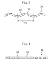
- Figure 3 is a partly enlarged plan view of a track in the secondary recording region 30 in Figure 1 .
- the secondary recording region 30 has a track 31 formed of a groove which wobbles at a pitch P2 different from the wobble pitch P1 of the track 21 in the primary recording region 20, and information pits 32 are formed along the track 31 to record a signal representative of control information at the time of the manufacture of the R disk 10 .
- the control information in the secondary recording region 30 includes an invalid key information item for inhibiting, when encrypted main data is copied into the primary recording region 20 , reproduction of the main data and an identification information item indicating that the disk 10 is an R disk.
- the wobble pitch P2 of the track 31 is set greater than the wobble pitch P1 of the track 21 .
- Figure 4 shows a variation of Figure 3 . It suffices for the track 31 in the secondary recording region 30 to be distinguishable from the wobbling track 21 in the primary recording region 20 , so that the track 31 does not necessarily have to wobble, as not all of the tracks in a DVD-ROM (i.e., a ROM disk) wobble.
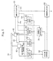
- FIG. 5 is a circuit block diagram illustrating an construction example of a DVD reproducing apparatus according to the present invention with the R disk 10 of Figure 1 mounted thereto.
- a ROM disk may be mounted to the DVD reproducing apparatus of Figure 5 instead of the R disk 10 .
- the DVD reproducing apparatus of Figure 5 comprises a spindle motor 41 for spinning the R disk 10 , an optical pickup 42 for scanning the R disk 10 under rotation with a light beam and reading a signal from the R disk 10 , and a slider 43 for shifting the optical pickup 42 in the radial direction of the R disk 10 .
- the apparatus of Figure 5 further includes an amplifier 50 , a mechanism controller part 60 , a wobble detector circuit 70 , a demodulator circuit 80, and a system controller circuit 90.
- the mechanism controller part 60 is constructed of a rotary servo circuit 61 , a shift controller circuit 62, a tracking servo circuit 63, and a focus servo circuit 64 .
- the rotary servo circuit 61 controls the number of revolutions of the spindle motor 41 according to instructions from the system controller circuit 90 so that the R disk 10 spins at a constant linear velocity (CLV).
- the shift controller circuit 62 controls the slider 43 according to instructions from the system controller circuit 90 so that the optical pickup 42 is shifted in the radial direction of the R disk 10 .
- the amplifier 50 amplifies an output of the optical pickup 42.
- the amplifier 50 has a function of performing addition/subtraction operations on a plurality of sensor signals forming an output of the optical pickup 42 thereby to generate a tracking error signal Ste and a focus error signal Sfe and a function of binarizing a modulated output of the optical pickup 42 thereby to generate a data detection signal Sdt.
- the tracking error signal Ste is provided to the tracking servo circuit 63 and to the wobble detector circuit 70 , the focus error signal Sfe is provided to the focus servo circuit 64 , and the data detection signal Sdt is provided to the demodulator circuit 80 .
- the tracking servo circuit 63 controls the optical pickup 42 so that the position at which the optical pickup 42 reads a signal (i.e., the light beam irradiation point) follows the tracks 21 and 31 of the R disk 10 , thereby to reduce the tracking error signal Ste.
- the wobble detector circuit 70 detects a signal for a frequency component which is contained in the tracking error signal Ste due to the wobbling of the track 21 and/or the track 31 and the detection result is sent to the system controller circuit 90.
- the focus servo circuit 64 controls vertical movement of the optical pickup 42 so that a light beam is focused to the R disk 10 , thereby to reduce the focus error signal Sfe.
- the demodulator circuit 80 is a circuit operable to demodulate the data detection signal Sdt to obtain main data and control information. The control information thus obtained is sent to the system controller circuit 90 .
- the system controller circuit 90 is a circuit operable to control the entirety of the DVD reproducing apparatus of Figure 5 .
- FIG 6 is a waveform diagram of the tracking error signal Ste when the primary recording region 20 in Figure 1 is being scanned with a light beam.
- the tracking error signal Ste contains a signal component having a wobble frequency F1 according to the wobble pitch P1 of the track 21 in the primary recording region 20. This is because the frequency characteristic of the tracking servo circuit 63 is set such that the tracking servo circuit 63 does not have a gain sufficient enough to enable the light beam to follow the wobbling track 21 at the wobble frequency F1.
- the wobble frequency F1 can be defined by the number of wobbles per second when the wobbling track 21 is scanned at a constant linear velocity V, as expressed below.
- the wobble frequency F1 is determined by the wobble pitch P1 of the track 21 and the constant linear velocity V.
- V 3.84 m/s
- the tracking error signal Ste when the secondary recording region 30 is being scanned with a light beam contains a signal component having a wobble frequency F2 lower than the wobble frequency F1 if the track 31 in the secondary recording region 30 wobbles at the pitch P2 (P2 > P1) as shown in Figure 3 . If the track 31 in the secondary recording region 30 does not wobble as shown in Figure 4 , this enables the light beam to accurately follow the track 31 and, as a result, the tracking error signal Ste becomes zero.
- the system controller circuit 90 in Figure 5 issues instructions to the shift controller circuit 62, thereby to make it possible to shift the optical pickup 42 in a direction toward an internal periphery of the R disk 10 until the optical pickup 42 reaches a specific point of the secondary recording region 30 at which the tracking error signal Ste no longer contains a signal component having the wobble frequency F1, so that even when false control information is copied into the primary recording region 20 such false control information is ignored. Further, the system controller circuit 90 issues instructions to the demodulator circuit 80 , thereby to make it possible to start, according to control information in the secondary recording region 30 represented by an output of the optical pickup 42 shifted up to the point of the secondary recording region 30 , reproduction of main data recorded in the primary recording region 20. In the case main data recorded in the primary recording region 20 of the R disk 10 is not encrypted, reproduction of the main data will continue, so that the main data recorded on the R disk 10 can be reproduced by the DVD reproducing apparatus of Figure 5 .
- Figure 7 shows one example of a data structure in the R disk 10 of Figure 1 . More detailedly, Figure 7 shows a state in which encrypted main data DATA-ROM on a ROM disk (not shown) is copied into the primary recording region 20 of the R disk 10 together with control information including a key information item KEY-ROM on the ROM disk and an identification information item ID-ROM indicating that the disk concerned is a ROM disk.
- the main data DATA-ROM, the false control information items KEY-ROM and ID-ROM are recorded along the track 21 which wobbles at the pitch P1 in the primary recording region 20 .
- control information including an invalid key information item KEY-R for inhibition of reproduction of the copied main data DATA-ROM and an identification information item ID-R indicating that the disk 10 is an R disk is recorded at the time of the manufacture of the R disk 10 .
- These genuine control information items KEY-R and ID-R are recorded along-the track 31 in the secondary recording region 30 which wobbles at the pitch P2 or does not wobble.
- the initial position of the optical pickup 42 is the read position of the main data DATA-ROM.
- the initial position of the optical pickup 42 is the position where the rotary servo circuit 61, the tracking servo circuit 63, and the focus servo circuit 64 start operating.
- the system controller circuit 90 issues instructions to the shift controller circuit 62 so as to shift the optical pickup 42 in a direction toward the internal periphery of the R disk 10 until certain control information is found out. In this way, the optical pickup 42 arrives at the false control information items KEY-ROM and ID-ROM.
- the wobble detector circuit 70 detects a signal component having the wobble frequency F1 in the tracking error signal Ste and the detection result is sent to the system controller circuit 90 .
- the system controller circuit 90 issues instructions to the shift controller circuit 62 so that the optical pickup 42 is further shifted toward the internal periphery of the R disk 10 until the next control information is found out. In this way, the optical pickup 42 finally arrives at the genuine control information items KEY-R and ID-R.
- the tracking error signal Ste at this point of time does not contain any signal component having the wobble frequency F1, so that these genuine control information items KEY-R and ID-R are accepted by the system controller circuit 90 .
- the system controller circuit 90 issues to the shift controller circuit' 62 instructions so that the optical pickup 42 is shifted in a direction toward the external periphery of the R disk 10 to the location of the main data DATA-ROM.
- the main data DATA-ROM is encrypted, so that the demodulator circuit 80 is unable to decrypt encryption of the main data even if the invalid key information item KEY-R is used.
- the system controller circuit 90 is able to cancel, when main data recorded in the primary recording region 20 is encrypted, reproduction of the main data by the demodulator circuit 80 according to the invalid key information item KEY-R. In this case, recording of the identification information item ID-R into the secondary recording region 30 may be omitted.
- the identification information item ID-R may be utilized for copy protection. That is to say, the system controller circuit 90 is able to cancel, when the identification information item indicates that the disk 10 concerned is an R disk and, in addition, the main data recorded in the primary recording region 20 is encrypted, reproduction of the main data by the demodulator circuit 80 . In this case, recording of the invalid key information item KEY-R into the secondary recording region 30 may be omitted.
- a ROM disk in place of the R disk 10 .
- encrypted main data is recorded in a primary recording region of the ROM disk
- control information including a key information item for decrypting the encryption and an identification information item indicating that the disk concerned is a ROM disk is recorded in a secondary recording region of the ROM disk.
- the DVD reproducing apparatus of Figure 5 facilitates seeking out genuine control information in the secondary recording region of the ROM disk.
- the tracking error signal Ste at this point in time does not contain any signal component having the wobble frequency F1, so that the genuine control information found out is accepted by the system controller circuit 90.
- the demodulator circuit 80 is able to decrypt encryption of the main data by the use of the genuine key information.
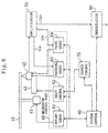
- FIG. 8 illustrates a construction example of a DVD reproducing apparatus according to the present invention.
- reference numeral 10 denotes an R disk having a primary recording region into which a user is able to record a data signal and a secondary recording region which is located on the side of the internal periphery of the primary recording region and into which a signal representative of control information is already prerecorded at the time of the manufacture of the R disk 10 .
- the R disk 10 does not necessarily have a wobbling track in the primary recording region.
- the DVD reproducing apparatus of Figure 8 is provided with a search controller circuit 75 in place of the wobble detector circuit 70 of Figure 5 .
- the search controller circuit 75 issues to the shift controller circuit 62 instructions thereby to shift the optical pickup 42 toward the internal periphery of the R disk 10 until the optical pickup 42 reaches its shift limit point, for searching the R disk 10 for every control information recorded therein. That the optical pickup 42 is shifted to the shift limit point is detected by the system controller circuit 90, for example, from the fact that a signal read by the optical pickup 42 stays unchanged. At this point in time, the system controller circuit 90 instructs the search controller circuit 75 not to conduct further searches.
- the system controller circuit 90 starts reproduction of the main data recorded in the primary recording region according to the control information in the secondary recording region obtained finally from an output of the optical pickup 42 during shifting of the optical pickup 42 , so that even when false control information is copied into the primary recording region of the R disk 10 such false control information is ignored.
Landscapes
- Engineering & Computer Science (AREA)
- Signal Processing (AREA)
- Computer Security & Cryptography (AREA)
- Optical Recording Or Reproduction (AREA)
- Signal Processing For Digital Recording And Reproducing (AREA)
Claims (7)
- Moyen d'enregistrement en forme de disque comprenant une région d'enregistrement primaire (20) et une région d'enregistrement secondaire (30) qui est placée sur le côté de la périphérie interne de ladite région d'enregistrement primaire (20),
dans lequel ladite région d'enregistrement primaire (20) possède une piste (21) sur laquelle un utilisateur peut enregistrer un signal de données ; et
dans lequel ladite région d'enregistrement secondaire (30) possède une piste (31) sur laquelle un signal représentatif d'une information de commande est déjà préenregistré sous la forme de microcuvettes d'information (32) au moment de la fabrication dudit moyen d'enregistrement,
caractérisé en ce que
ladite information de commande dans ladite région d'enregistrement secondaire (30) comprend un élément d'information de clé d'invalidité (KEY-R) destinée à inhiber, quand on copie des données principales cryptées dans ladite région d'enregistrement primaire, la reproduction desdites données principales ;
dans lequel ladite piste (21) de ladite région d'enregistrement primaire (20) est wobulée selon un premier pas (P1) ; et
dans lequel ladite piste (31) de ladite région d'enregistrement secondaire (30) est wobulée selon un deuxième pas (P2) différent du premier pas (P1) ou n'est pas wobulée. - Moyen d'enregistrement selon la revendication 1, dans lequel ladite information de commande dans ladite région d'enregistrement secondaire (30) comprend un élément d'information d'identification (ID-R) nécessaire au moment de la reproduction et représentative dudit moyen d'enregistrement.
- Appareil de reproduction destiné à la reproduction de données principales enregistrées sur un moyen d'enregistrement (10), ledit moyen - d'enregistrement (10) comprenant une région d'enregistrement primaire (20) possédant une piste (21) wobulée selon un premier pas (P1) sur laquelle un utilisateur peut enregistrer des données et comprenant une région d'enregistrement secondaire (30) placée sur le côté de la périphérie interne dudit moyen d'enregistrement (10) possédant une piste (31) sur laquelle une information de commande comprenant un élément d'information de clé d'invalidité (KEY-R) est préenregistrée, ladite piste (31) de ladite région d'enregistrement secondaire (30) étant wobulée selon un deuxième pas (P2) différent du premier pas (P1) ou n'étant pas wobulée, ledit appareil de reproduction comprenant :un moyen (61) destiné à faire tourner ledit moyen d'enregistrement (10) ;une tête de lecture (42) destinée à lire un signal sur ledit moyen d'enregistrement (10) en rotation ;un moyen (63) à l'aide duquel une position de lecture d'un signal par ladite tête de lecture (42) suit lesdites pistes (21, 31) dudit moyen d'enregistrement (10) ;un moyen (50) destiné à générer un signal d'erreur de suivi délivré par une sortie de ladite tête de lecture (42) ;des moyens (62, 70, 90) destinés à décaler ladite tête de lecture (42) dans une direction orientée vers la périphérie interne dudit moyen d'enregistrement (10) jusqu'à ce que ladite tête de lecture (42) atteigne une position radiale spécifique de ladite région d'enregistrement secondaire (30) à laquelle ledit signal d'erreur de suivi ne contient plus de composante de signal ayant une fréquence qui est déterminée par ledit premier pas (P1) se rapportant à la wobulation de ladite piste (21) dans ladite région d'enregistrement primaire (20), et à n'accepter qu'une information de commande représentée par une sortie de ladite tête de lecture (42) décalée dans ladite position radiale spécifique de ladite région d'enregistrement secondaire (30) de manière à ce que les informations de commande erronées copiées dans ladite région d'enregistrement primaire (20) soient ignorées ; etdes moyens (80, 90) destinés à démarrer la reproduction des données principales enregistrées dans ladite région d'enregistrement primaire (20) en conformité avec ladite information de commande acceptée.
- Appareil de reproduction selon la revendication 3, dans lequel ledit appareil de reproduction comprend en outre un moyen (90) destiné à annuler la reproduction desdites données principales en conformité avec ledit élément d'information de clé d'invalidité (KEY-R) quand les données principales enregistrées dans ladite région d'enregistrement primaire (20) sont cryptées.
- Appareil de reproduction selon la revendication 3 ou 4,
dans lequel ladite information de commande acceptée comprend un élément d'information d'identification (ID-R) représentatif du type dudit moyen d'enregistrement ; et
dans lequel ledit appareil de reproduction comprend un outre un moyen (90) destiné à annuler la reproduction desdites données principales quand ledit élément d'information d'identification (ID-R) indique que l'enregistrement d'un signal de données dans ladite région d'enregistrement primaire (20) par un utilisateur est possible et qu'en outre les données principales enregistrées dans ladite région d'enregistrement primaire (20) sont cryptées. - Appareil de reproduction selon l'une quelconque des revendications 3 à 5, comprenant en outre des moyens (80, 90) destinés à continuer la reproduction desdites données principales quand les données principales enregistrées dans ladite région d'enregistrement primaire (20) ne sont pas cryptées.
- Appareil de reproduction selon l'une quelconque des revendications 3 à 6, comprenant en outre des moyens (75, 90) destinés à décaler ladite tête de lecture (42) dans une direction orientée vers la périphérie interne dudit moyen d'enregistrement (10), de manière à rechercher une information de commande jusqu'à ce que le décalage de ladite tête de lecture (42) soit arrêté quand on a atteint un point de limite de décalage, et à n'accepter que l'information de commande représentée par une sortie de ladite tête de lecture (42) pendant le décalage de ladite tête de lecture (42) et obtenue avant finalement qu on ait atteint ledit point de limite de décalage.
Applications Claiming Priority (7)
| Application Number | Priority Date | Filing Date | Title |
|---|---|---|---|
| JP21368598 | 1998-07-29 | ||
| JP21368598 | 1998-07-29 | ||
| JP23818198 | 1998-08-25 | ||
| JP23818098 | 1998-08-25 | ||
| JP23818198 | 1998-08-25 | ||
| JP23818098 | 1998-08-25 | ||
| PCT/JP1999/004083 WO2000007183A1 (fr) | 1998-07-29 | 1999-07-28 | Appareil de reproduction et support enregistre |
Publications (3)
| Publication Number | Publication Date |
|---|---|
| EP1102249A1 EP1102249A1 (fr) | 2001-05-23 |
| EP1102249A4 EP1102249A4 (fr) | 2002-07-31 |
| EP1102249B1 true EP1102249B1 (fr) | 2003-11-05 |
Family
ID=27329532
Family Applications (1)
| Application Number | Title | Priority Date | Filing Date |
|---|---|---|---|
| EP99933163A Expired - Lifetime EP1102249B1 (fr) | 1998-07-29 | 1999-07-28 | Appareil de reproduction et support enregistre |
Country Status (5)
| Country | Link |
|---|---|
| EP (1) | EP1102249B1 (fr) |
| KR (1) | KR100614360B1 (fr) |
| CN (1) | CN1172298C (fr) |
| DE (1) | DE69912613T2 (fr) |
| WO (1) | WO2000007183A1 (fr) |
Families Citing this family (22)
| Publication number | Priority date | Publication date | Assignee | Title |
|---|---|---|---|---|
| US6606290B2 (en) | 1999-05-21 | 2003-08-12 | Matsushita Electric Industrial Co., Ltd. | Recordable optical disk |
| DE60006538T2 (de) * | 1999-05-21 | 2004-09-30 | Matsushita Electric Industrial Co., Ltd., Kadoma | Beschreibbare optische Platte |
| JP3962522B2 (ja) * | 2000-02-14 | 2007-08-22 | パイオニア株式会社 | 情報記録媒体 |
| JP2001243639A (ja) * | 2000-02-28 | 2001-09-07 | Pioneer Electronic Corp | サーボ制御装置及びサーボ制御方法並びに情報再生装置 |
| JP3922424B2 (ja) | 2000-07-25 | 2007-05-30 | パイオニア株式会社 | 光学式記録媒体、光学式記録媒体製造装置及び光学式記録媒体製造方法 |
| KR100457512B1 (ko) | 2001-11-29 | 2004-11-17 | 삼성전자주식회사 | 광 기록 매체, 광 기록 매체 재생 장치 및 방법 |
| KR100457511B1 (ko) | 2001-11-29 | 2004-11-17 | 삼성전자주식회사 | 광 기록 매체, 광 기록 매체 재생 장치 및 방법 |
| AU2003201839A1 (en) * | 2002-04-01 | 2003-10-23 | Sony Corporation | Recording method for recording data on a storage medium |
| JP2005524188A (ja) * | 2002-04-25 | 2005-08-11 | コーニンクレッカ フィリップス エレクトロニクス エヌ ヴィ | データを記録する装置、記録担体及びデータを記録する方法 |
| PL372448A1 (en) * | 2002-06-20 | 2005-07-25 | Koninklijke Philips Electronics N.V. | Method and device for protecting user information against manipulations |
| US7649824B2 (en) * | 2002-07-01 | 2010-01-19 | Panasonic Corporation | Optical storage medium control data region |
| KR100739672B1 (ko) * | 2002-09-10 | 2007-07-13 | 삼성전자주식회사 | 광정보 저장매체 및 데이터의 재생 방법 |
| US7437053B2 (en) * | 2003-01-15 | 2008-10-14 | Matsushita Electric Industrial Co., Ltd. | Digital video recorder, method of driving the video recorder and program |
| WO2004097826A1 (fr) | 2003-04-29 | 2004-11-11 | Koninklijke Philips Electronics N.V. | Systeme de protection anti-copie d'un support d'information |
| EP1644926A1 (fr) * | 2003-07-07 | 2006-04-12 | Lg Electronics Inc. | Support d'enregistrement, son procede de configuration d'informations de controle, dispositif et procede d'enregistrement et/ou reproduction mettant ce support en application |
| KR100976473B1 (ko) * | 2003-07-08 | 2010-08-18 | 엘지전자 주식회사 | 광디스크 및 광디스크의 디스크정보 기록방법 |
| US8271752B2 (en) | 2004-03-12 | 2012-09-18 | Lg Electronics, Inc. | Recording medium, method and apparatus for recording on recordable recording medium, and method for managing backup files of the same |
| KR20060043573A (ko) * | 2004-03-12 | 2006-05-15 | 엘지전자 주식회사 | 기록매체 및 기록매체에의 기록방법 및 기록장치와 기록매체의 백업 파일 관리방법 |
| US8249424B2 (en) | 2006-03-24 | 2012-08-21 | Pioneer Corporation | Information recording medium in which groove tracks are wobbled by frequency 2n times wobble frequency of standard |
| EP2009636B1 (fr) | 2006-03-24 | 2012-11-28 | Pioneer Corporation | Procédé de reproduction d'informations |
| WO2008029364A1 (fr) * | 2006-09-07 | 2008-03-13 | Koninklijke Philips Electronics N.V. | Disque optique inscriptible, procédé et dispositif d'enregistrement pour enregistrer un contenu protégé par css sur celui-ci |
| KR20080089005A (ko) * | 2007-03-30 | 2008-10-06 | 삼성전자주식회사 | 기록형 광 정보 저장매체 |
Family Cites Families (8)
| Publication number | Priority date | Publication date | Assignee | Title |
|---|---|---|---|---|
| NL8801275A (nl) * | 1988-05-18 | 1989-12-18 | Philips Nv | Optekensysteem alsmede registratiedrager en schrijfinrichting voor toepassing in het systeem. |
| JPH025111U (fr) * | 1988-06-17 | 1990-01-12 | ||
| EP0930614B1 (fr) * | 1991-12-02 | 2004-03-31 | Philips Electronics N.V. | Système d'information fermé avec protection de copie |
| JP3257579B2 (ja) * | 1994-11-28 | 2002-02-18 | 日本ビクター株式会社 | 光ディスク及びそのチェック装置 |
| WO1996038842A1 (fr) * | 1995-05-31 | 1996-12-05 | Sony Corporation | Moyen d'enregistrement, dispositif d'enregistrement, procede de reproduction et dispositif de reproduction |
| JPH0981938A (ja) * | 1995-09-14 | 1997-03-28 | Matsushita Electric Ind Co Ltd | 不正複写防止機能付き光ディスクおよび光ディスク装置 |
| JPH09259576A (ja) * | 1996-03-25 | 1997-10-03 | Toshiba Corp | 複数管理領域を持つ情報記録ディスク |
| US6163521A (en) * | 1997-04-16 | 2000-12-19 | Matsushita Electric Industrial Co., Ltd. | Disk having read-only and read-write areas |
-
1999
- 1999-07-28 WO PCT/JP1999/004083 patent/WO2000007183A1/fr not_active Ceased
- 1999-07-28 DE DE69912613T patent/DE69912613T2/de not_active Expired - Fee Related
- 1999-07-28 KR KR1020007010160A patent/KR100614360B1/ko not_active Expired - Fee Related
- 1999-07-28 EP EP99933163A patent/EP1102249B1/fr not_active Expired - Lifetime
- 1999-07-28 CN CNB998036684A patent/CN1172298C/zh not_active Expired - Fee Related
Also Published As
| Publication number | Publication date |
|---|---|
| KR100614360B1 (ko) | 2006-08-18 |
| CN1172298C (zh) | 2004-10-20 |
| DE69912613T2 (de) | 2004-04-15 |
| WO2000007183A1 (fr) | 2000-02-10 |
| EP1102249A4 (fr) | 2002-07-31 |
| EP1102249A1 (fr) | 2001-05-23 |
| KR20010041866A (ko) | 2001-05-25 |
| DE69912613D1 (de) | 2003-12-11 |
| CN1292916A (zh) | 2001-04-25 |
Similar Documents
| Publication | Publication Date | Title |
|---|---|---|
| EP1102249B1 (fr) | Appareil de reproduction et support enregistre | |
| KR100450434B1 (ko) | 정보 기록매체 | |
| US6597654B2 (en) | Recordable optical disk | |
| EP1204102B1 (fr) | Méthode d'enregistrement pour un disque optique enregistrable | |
| JP3173607B1 (ja) | 光ディスクへの記録方法 | |
| JP3169365B2 (ja) | 光ディスク | |
| JP3173604B1 (ja) | 光ディスク | |
| JP4131660B2 (ja) | 記録媒体、記録再生装置および再生装置 | |
| JP3173606B1 (ja) | 光ディスク | |
| JP3173509B1 (ja) | 光ディスク | |
| JP3173605B1 (ja) | 光ディスク | |
| EP1300837A2 (fr) | Lecteur de disque | |
| JPWO2000007183A1 (ja) | 再生装置、および記録媒体 |
Legal Events
| Date | Code | Title | Description |
|---|---|---|---|
| PUAI | Public reference made under article 153(3) epc to a published international application that has entered the european phase |
Free format text: ORIGINAL CODE: 0009012 |
|
| 17P | Request for examination filed |
Effective date: 20010116 |
|
| AK | Designated contracting states |
Kind code of ref document: A1 Designated state(s): AT BE CH CY DE DK ES FI FR GB GR IE IT LI LU MC NL PT SE |
|
| A4 | Supplementary search report drawn up and despatched |
Effective date: 20020619 |
|
| AK | Designated contracting states |
Kind code of ref document: A4 Designated state(s): AT BE CH CY DE DK ES FI FR GB GR IE IT LI LU MC NL PT SE |
|
| 17Q | First examination report despatched |
Effective date: 20021016 |
|
| GRAH | Despatch of communication of intention to grant a patent |
Free format text: ORIGINAL CODE: EPIDOS IGRA |
|
| GRAS | Grant fee paid |
Free format text: ORIGINAL CODE: EPIDOSNIGR3 |
|
| GRAA | (expected) grant |
Free format text: ORIGINAL CODE: 0009210 |
|
| AK | Designated contracting states |
Kind code of ref document: B1 Designated state(s): DE FR GB |
|
| REG | Reference to a national code |
Ref country code: GB Ref legal event code: FG4D |
|
| REF | Corresponds to: |
Ref document number: 69912613 Country of ref document: DE Date of ref document: 20031211 Kind code of ref document: P |
|
| REG | Reference to a national code |
Ref country code: IE Ref legal event code: FG4D |
|
| ET | Fr: translation filed | ||
| PLBE | No opposition filed within time limit |
Free format text: ORIGINAL CODE: 0009261 |
|
| STAA | Information on the status of an ep patent application or granted ep patent |
Free format text: STATUS: NO OPPOSITION FILED WITHIN TIME LIMIT |
|
| 26N | No opposition filed |
Effective date: 20040806 |
|
| REG | Reference to a national code |
Ref country code: IE Ref legal event code: MM4A |
|
| PGFP | Annual fee paid to national office [announced via postgrant information from national office to epo] |
Ref country code: FR Payment date: 20060719 Year of fee payment: 8 |
|
| PGFP | Annual fee paid to national office [announced via postgrant information from national office to epo] |
Ref country code: DE Payment date: 20060720 Year of fee payment: 8 |
|
| PGFP | Annual fee paid to national office [announced via postgrant information from national office to epo] |
Ref country code: GB Payment date: 20060726 Year of fee payment: 8 |
|
| GBPC | Gb: european patent ceased through non-payment of renewal fee |
Effective date: 20070728 |
|
| PG25 | Lapsed in a contracting state [announced via postgrant information from national office to epo] |
Ref country code: DE Free format text: LAPSE BECAUSE OF NON-PAYMENT OF DUE FEES Effective date: 20080201 |
|
| PG25 | Lapsed in a contracting state [announced via postgrant information from national office to epo] |
Ref country code: GB Free format text: LAPSE BECAUSE OF NON-PAYMENT OF DUE FEES Effective date: 20070728 |
|
| REG | Reference to a national code |
Ref country code: FR Ref legal event code: ST Effective date: 20080331 |
|
| PG25 | Lapsed in a contracting state [announced via postgrant information from national office to epo] |
Ref country code: FR Free format text: LAPSE BECAUSE OF NON-PAYMENT OF DUE FEES Effective date: 20070731 |